Table of Contents
Advertisement
Quick Links
Thank you for purchasing this product.
Read this instruction manual before using the product to make sure that you use it correctly.
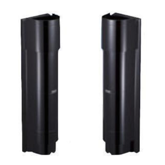
This device is an opposed type photoelectric beam sensor that consists of a
photo transmitter that transmits infrared light, and a photo receiver for
the transmitted light, as shown in the illustration on the right.
The infrared light transmitted from the transmitter expands in a cone
shape, while the light beams enter the receiver.
The straight line that connects the transmitter with the receiver is the
detection line.
If the detection line is obstructed (light is obstructed for more than 0.05 –
0.7 seconds), the receiver detects this break in the light beams, and outputs
a signal.
In order to ensure that the detection line has sufficient margin of
sensitivity, adjust the direction of the light beams before placing the
system into operation.
Providing sufficient margin of sensitivity reduces the occurrence of
malfunction caused by dense fog, heavy rain, frost, snow, and other such
weather conditions.
(1) DOUBLE MODULATION
Double modulated beams are designed to
distinguish the external lights.
It increases the reliability in the outdoor security
system.
(2) WIDE BEAM
The pitch between upper beam and lower one is
widened more than old models.
False alarm by birds and falling leaves reduces
drastically.
(3) QUAD HIGH POWER BEAM
The beam power is 100 times of the minimum
requirement.
The beam distance is 10 times of the described
specification.
This high power beam also realizes the reliability
against the harsh conditions like fog, snow, heavy
rain.
(4) LOW CURRENT CONSUMPTION
50% less than remaining models.
The battery size may reduce, wiring diameter may
lessen, installation cost may decrease.
(5) ECOLOGY
RoHS adapted – Environment friendly.
Free from Lead, Mercury, Cadmium, Hexavalent
chromium, Polybrominated biphenyl, Polybromi-
nated diphenyl ether.
(6) INSECT/ WATER PREVENT
Anti-insect bushing and special gasket enable
IP65 rated tight housing.
PHOTOELECTRIC BEAM SENSOR
PXB- 50F:OUTDOOR 165ft ( 50m)
PXB-100F:OUTDOOR 330ft (100m)
PXB-200F:OUTDOOR 660ft (200m)
Instruction Manual
Main Features
Transmitter
(7) DRIP-PROOF HOUSING
Prevents rain and snow from streaming down
the front side of housing, helping to avoid false
alarm.
(8)
DUAL RING SIGHT
Enables better and clear view for easy beam
alignment.
(9)
TARGET COLOR
The vivid color of the internal structure can be
recognized easily from the far end in the beam
alignment procedure.
The color differs between a transmitter and a
receiver which helps easy installation and
checking.
(10) INCREASED ANGLE
ADJUSTMENT ALLOWANCE
Vertically ±20˚ compared with previous version.
It may adapt to the slope installation flexibly.
(11) WIRELESS ALIGNMENT CHECKER
Enables easy and accurate beam alignment.
(Sold separately)
(12) LIGHTNING/SURGE PROTECTION
Minimize the damage by the induced lightning
through wirings.
It may stand 10000V under normal mode,
15000V under common mode.
①
Detection line
Receiver
Coverage of light beams
Advertisement
Table of Contents

Related Manuals for Takex PXB-50F


Summary of Contents for Takex PXB-50F
- Page 1 PHOTOELECTRIC BEAM SENSOR PXB- 50F:OUTDOOR 165ft ( 50m) PXB-100F:OUTDOOR 330ft (100m) PXB-200F:OUTDOOR 660ft (200m) Instruction Manual Thank you for purchasing this product. Read this instruction manual before using the product to make sure that you use it correctly. This device is an opposed type photoelectric beam sensor that consists of a Detection line photo transmitter that transmits infrared light, and a photo receiver for the transmitted light, as shown in the illustration on the right.
-
Page 2: Table Of Contents
— TABLE OF CONTENTS — 1 PRODUCT COMPONENTS PARTS DESCRIPTION............• Optical Axis Fine Adjustment Using the Sound Check..... ACCESSORIES..............• Optical Axis Fine Adjustment Using the Monitor NAMES OF OPERATION SECTION........Output Voltage..............2 PRECAUTIONS................• Optical Axis Fine Adjustment Using the Alignment 3 PRECAUTIONS Wireless Checker (Sold Separately)........ -
Page 3: Names Of Operation Section
NAMES OF OPERATION SECTION [Receiver] [Transmitter] Light reception authorization LED: Red Alarm LED (Upper/Lower) : Red Transmitter LED: Red Sensitivity Upper/lower changeover switch (Upper/Lower) attenuation LED “8 EXPLANATION OF FUNCTIONS : Red (8-3 UPPER/LOWER CHANGEOVER Upper/lower changeover switch FUNCTION)” Monitor jack “8 EXPLANATION OF FUNCTIONS (8-3 UPPER/LOWER CHANGEOVER FUNCTION)”... -
Page 4: Protection Distance And Range Of Light Beam Coverage
Cautions when using the outdoor photoelectric beam sensor (Daily maintenance) 1. In areas where there are trees or weeds, the photoelectric beams may get obstructed by overgrown branches or leaves. As this may cause erroneous detection, be sure to trim down leaves and branches according to the growth of the plants. Furthermore, the photoelectric beams may get obstructed by swaying branches or leaves due to wind. -
Page 5: Optical Axis Adjustment Range
• Refer to the diagram below, and install the sensors within the optical axis adjustment OPTICAL AXIS ADJUSTMENT RANGE range. (Photoelectric beams are drawn in simplified form) (Example 1) (Example 2) (Example 3) Top View +90° (Movable within 180°) 90° –90°... -
Page 6: Installation Method
INSTALLATION METHOD WALL INSTALLATION METHOD sensor body. the installation plate. Cover Cover fixing screw Sensor body Installation plate Sensor fixing screw the space shown by the dotted lines is allocated before 0.39"(10 mm) Marking 0.39"(10 mm) About the cut bush This work is required as an insect-proof and dust-proof countermeasure for the sensor exterior. -
Page 7: Pole Installation Method
Note: This device can be attached to a pole with diameters of 1.65" (φ42 mm) to POLE INSTALLATION METHOD 1.95" (φ49 mm). Cover Cover fixing screws Sensor body Installation plate Sensor fixing screws Countersunk oval-head screw (M4x20) Note: Accessories Pole About the cut bush installation fitting... -
Page 8: Wiring Method
No-voltage contact: b contact No-voltage contact: b contact Built-in contact protection resistance Built-in contact protection resistance WIRING DISTANCE BETWEEN SENSOR AND POWER SUPPLY Part No. PXB-100F PXB-200F PXB-50F Size of 12V DC 24V DC 12V DC 24V DC 12V DC 24V DC electrical cable used Up to 2,700ft. -
Page 9: Optical Axis Adjustment
OPTICAL AXIS ADJUSTMENT By aligning the optical axis correctly, a protection line with sufficient margin of sensitivity can be created, reducing the occurrence of malfunction. Always adjust the optical axis on both upper and lower levels. NAMES AND FUNCTIONS OF OPTICAL AXIS ADJUSTMENT PARTS Reflector Section Horizontal/Vertical Angle Adjustment Method Names of the Optical Unit Coarse adjustment... -
Page 10: Optical Axis Adjustment Using The Alignment Mechanism
OPTICAL AXIS ADJUSTMENT USING THE ALIGNMENT MECHANISM Move the swivel base and swing arm so that the opposite device is roughly aligned with the view finder. Vertical angle adjustment Horizontal angle adjustment Look closely through the view finder, and adjust the position so that the sensor of the opposite device is visible at the center of the ring using the horizontal and vertical angle fine adjustment screws. -
Page 11: Optical Axis Fine Adjustment Using The Sound Check
To improve accuracy of optical axis Perform the procedure of “Optical Axis Adjustment Using the Sound Check”, “Optical Axis Fine Adjustment Using the Monitor Output Voltage”, or “Optical Axis Fine Adjustment Using the Alignment Wireless Checker”. Optical Axis Fine Adjustment Using the Sound Check The sound check function indicates the light reception level by using high and low pitch tones. -
Page 12: Optical Axis Fine Adjustment Using The Monitor Output Voltage
Optical Axis Fine Adjustment Using the Monitor Output Voltage Accurate adjustments of the optical axis can be achieved by checking the light reception level value using the voltage of the monitor output. <<Caution>> First, check only the transmission on the upper level and reception on the upper level , and then check only the transmission on the lower level and reception on the lower level. -
Page 13: Operation Check
OPERATION CHECK Be sure to perform an operation check after the optical axis adjustment. When the optical axis adjustment is completed, attach the cover. Transmitter Obstruct the sensor beams near the sensor or the center of the detection line and check that an alarm can be output correctly. -
Page 14: Upper/Lower Changeover Function
TROUBLESHOOTING • Check the device by referring to the table below. If you cannot restore the device to a normal condition after the check, contact the place of purchase or TAKEX. Status Cause... -
Page 15: Specifications
SPECIFICATIONS Model PXB-50F PXB-100F PXB-200F Near infrared pulsed beam interruption system Detection system (TR-RE 4 beam simultaneous interruption) Infrared beam Double modulation pulsed beam by LED Protection distance Outdoor 165' (50 m) or less Outdoor 330' (100 m) or less Outdoor 660' (200 m) or less Max. - Page 16 Limited Warranty : TAKEX products are warranted to be free from defects in material and workmanship for 12 months from original date of shipment. Our warranty does not cover damage or failure caused by natural disasters, abuse, misuse, abnormal usage, faulty installation, improper maintenance or any repairs other than those provided by TAKEX.
Need help?
Do you have a question about the PXB-50F and is the answer not in the manual?
Questions and answers