Table of Contents
Advertisement
Quick Links
Thank you for purchasing our photoelectric beam sensor.
This sensor will provide long and dependable service when properly installed.
Please read this Instruction Manual carefully for correct and e ective use.
Please note : This sensor is designed to detect intrusion and to initiate an alarm ; it is not a burglary-preventing device.
TAKEX is not responsible for damage, injury or losses caused by accident, theft, Acts of God ( including inductive
surge by lightning ), abuse, misuse, abnormal usage, faulty installation or improper maintenance.
1
PRODUCT DESCRIPTION
The PR-30BE, adopting Time of Flight technology, consist of a
sensor (integrating both a transmitter and a receiver inside)
and a reflector. As illustrated, an infrared beam, projected by
the transmitter is reflected back to the receiver, forming a
protection loop along the path.
When the protection loop is interrupted, the receiver initiates
an alarm. The receiver not only monitors the change in the
amount of light that is reflected and returned, but also measures
and monitors the time (distance) of the return. As a result, stable
protection line can be constructed by preventing the surrounding
environment and material/color of any shielding objects from affecting the detection.
●This sensor requires only one-side wiring, so can be
used in places where it is difficult to wire on two sides.
●Both beam reception level and detection distance are
monitored to form a stable protection line.
2
PARTS DESCRIPTION
Cover
(Note)
The cover includes a
photocatalytic coating for
weather protection.
Avoid clearning with a
cloth.
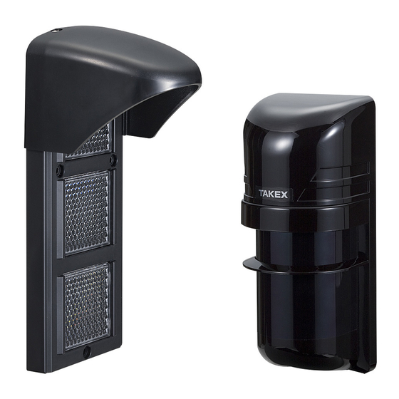
REFLECTOR
PHOTOELECTRIC BEAM SENSOR
: OUTDOOR 30m (100 ft.)
PR-30BE
: INDOOR
Instruction Manual
Terminals
Monitor output
changeover switch
Monitor jack
Alarm LED
※Sensitivity attenuation
/Environment LED
Lens unit
View finder
Vertical
adjustment
screw
40m (135 ft.)
Transmitter
Receiver
Sensor
●The optical unit inside the sensor is adjustable by ±90°horizontally,
and ±5°vertically for flexibility in various applications.
●Beam alignment can be adjusted only on the sensor side by utilizing the
viewfinder, monitor output, and sound check function.
●Environmental trouble signal is output when the beam reception level is
reduced below an acceptable level.
SENSOR
Function setting
switch
Distance setting
button
Monitor jack
Horizontal
adjustment
ACCESSORY
Pole mounting plate
: 2pcs.
Countersunk
oval-head screw
M4×20 : 6
Self-tapping
screws
φ4×30 : 5
①
Grommet
Mounting plate
※Sensitivity attenuation
/Environment LED
Cover open
: Sensitivity attenuation LED
Cover close
: Environment LED
OPTIONALS
Pole bracket
: 2pcs.
Screw
M4×6 : 2
Push rivet
Reflector
L fittings
BL-11
Advertisement
Table of Contents

Related Manuals for Takex PR-30BE


Summary of Contents for Takex PR-30BE
- Page 1 Please note : This sensor is designed to detect intrusion and to initiate an alarm ; it is not a burglary-preventing device. TAKEX is not responsible for damage, injury or losses caused by accident, theft, Acts of God ( including inductive surge by lightning ), abuse, misuse, abnormal usage, faulty installation or improper maintenance.
-
Page 2: Description Of The Display
This manual describes the precautions to be observed for safe operation of this device by classifying them into the PRECAUTIONS following categories. As these are important, be sure to read and strictly observe them. Description of the Display Indicates information that, if ignored and the device is handled incorrectly, may result in death or serious injury. Warning Indicates information that, if ignored and the device is handled incorrectly, may result in injury or damage to property alone. Caution This symbol indicates a prohibited action, with the specific action shown near the symbol. Do not disassemble Example: Indicates useful information. Warning Do not use the sensors powered with a voltage level other Do not disassemble or modify this device. It may cause a fire, than the indicated power supply voltage specified (between electrical shock, or malfunction of the device. 10.5 to 30V DC). It may cause a fire or electrical shock. Do not connect a device that exceeds the capacity shown to If smoke, an abnormal odor or sound is found, leaving it ... -
Page 3: Before Installation
In order to use this sensor correctly, thoroughly read this instruction manual and BEFORE INSTALLATION select the mounting position and protection distance. PROTECTION DISTANCE Protection distance (between sensor/reflector) * should not exceed the rated range. Outdoor protection distance may be reduced due to A φ the possible effect of mist, fog, frost, rain, or condensation on the sensor unit cover and reflector unit, which can cause false alarms. Sensor L Reflector φA = 0.2×L OUTDOOR 0.5 to 30m (1.7ʼ to 100 ft.) <Example> INDOOR 0.5 to 40m (1.7ʼ to 135 ft.) L = 10m (33ʼ ) : φA = φ2.0m (6.6ʼ) L = 30m (100ʼ) : φA = φ6.0m (20ʼ) Center of CAUTIONS ON INSTALLATION Center of HEIGHT OF INSTALLATION the sensor the reflector Install the sensor at a height of 80 to ※Align the center of the sensor with the center 100cm(31”to 39”) to catch a human ... -
Page 4: Installation
INSTALLATION ※In case of indoor installation, the hood can be removed if it is not required. WALL MOUNTING ①Loosen 2 x fixing screws on the top of reflector and remove the hood. ●Sensor ②Remove the push rivet. ①Remove cover from unit and slide the mounting plate ③Invert the reflector with the hood fixing holes facing downwards and upwards to detach it. fix into position with 2 x (φ4x30mm) self-tapping screws using the upper and lower holes. ④Insert 2 x push rivets into the fixing screw holes to seal them. Cover Hood fixing screws ① Mounting Hood plate Self-tapping screws ③ Push rivet 196mm (7.72”) ② ②Pull the wire through to the installation position. Push rivet ③Make one hole in the grommet on the mounting plate ④ Upside down and pull the wire through it. Secure the plate with 2 x self-tapping screws. (φ4x30mm) Self-tapping screws (Note)In case of outdoor installation, please do not remove hood. 83.5mm (3.29") POLE MOUNTING Holes ※Applicable pole size : Outside dia. 42mm (1.65") to 49mm (1.93"). ※Fix the pole mounting plates of the sensor and the reflector at the same height to adjust them to each center. -
Page 5: Terminal Configuration
For back-to-back and right angle mounting Installation with BL-11 (Sold separately) (Note)Applicable only to the sensor, not to the reflector. (Note)Applicable only to the sensor, not to the reflector. ①Fix the BL-11 to the wall by 2 x self-tapping screws. (φ4x20mm) ①Fix the first pole mounting plate with first pole bracket. (using keyhole) ②Pass the second pole bracket under the first pole ②Fix the reflector to the BL-11 by 2 x oval countersunk head screws mounting plate and fix the second pole mounting plate (M4x20). upside down. ③Insert the push rivet into the lower hole in order to seal it. ※Follow the same procedure as wall mounting (from③) for wiring ① BL-11 Reflector Self-tapping ② screws Screws ③ Push rivet WIRING CONNECTION TERMINAL CONFIGURATION ● Example connection 1 Power Alarm ①②③④... - Page 6 ②Set tone indicator setting to “ON”. 2 Distance check If the tone indicator is undesirable (at night), proceed directly to ④. ①Ensure that the monitor output changeover switch is set to "Distance". When adjusting the optical axis by changing the Tone indicator installation distance, long press the distance setting button (short pip for 5 seconds or more) before proceeding to the next step. Distance Reception Function setting switch Monitor output ③Fine-tune the optical unit the tone becomes continuous and as changeover switch high-pitched as possible. Especially at short distance, the high-power beam output from (Note) the transmitter may reflect on objects If no sound comes out, the sensor unit may not face the direction of the (walls, signboards, utility poles, etc.) reflector. In this case, go back to [1. Before checking] and do the setting Utility poles, etc. near to the protection line. again. Also check that the tone indicator switch is ON. Therefore, adjust correctly Beam reflected when installing. on objects Lens unit Vertical angle Beam on Vertical protection line adjustment screw When the light reception level is...
-
Page 7: Operation Check
FUNCTIONS Function setting switch ①Alarm output changeover <Caution> (Function setting switch: DIP 1) ・If the interruption time is shorter than the response time, there is no N.C. N.O. 1 2 3 4 5 6 detection of obstructing object. N.C. or N.O. can be selected ・If there is a possibility that large flying objects (birds, falling leaves, etc.) for alarm output logic. N.C. (Factory set) shield the optical axis, set the response time longer, considering the installation conditions. ②Environmental output changeover Function setting switch ④ Tone Indicator (Function setting switch : DIP 5) (Function setting switch: DIP 2) When tone indicator switch is ON, reception level is notified with sound. N.C. N.O. N.C. or N.O. can be selected (Only when Monitor output switch is set to “Reception”) 1 2 3 4 5 6 for environmental output logic. ・As the light reception level increases, the sound changes from N.C. (Factory set) intermittent tone to continuous tone, and the pitch increases after that. ・This function operates only when the sensor cover is removed. -
Page 8: Troubleshooting
TAKEX, including implied warranties for merchantability and implied warranties for tness, are limited in duration to 12 months from original date of shipment. During the Warranty Period, TAKEX will repair or replace, at its sole option,free of charge, any defective parts returned prepaid. Please provide the model number of the products, original date of shipment and nature of di culty being experienced.
Need help?
Do you have a question about the PR-30BE and is the answer not in the manual?
Questions and answers