Table of Contents
Advertisement
User Manual
Motor Control for Height Adjustable TV-Set
Carriers
LogicSP-2-1 / LogicSP-2-2
LOGICDATA Electronic & Software Entwicklungs GmbH
Hinterleitenstrasse 22a
A 8523 Frauental / Austria
Rev. 0
Availability and specifications are subject to change without prior notice. LOGICDATA assumes no
liability for damage caused by improper use of the products described herein. LOGICDATA will at
point of delivery replace/repair defective products covered by the warranty. No liability is assumed
beyond such replacement/repair. Please contact LOGICDATA directly on inquiries or custom
requirements.
© 2006 LOGICDATA
Advertisement
Table of Contents

Related Manuals for LOGICDATA LogicSP-2-1


Summary of Contents for LOGICDATA LogicSP-2-1
- Page 1 Availability and specifications are subject to change without prior notice. LOGICDATA assumes no liability for damage caused by improper use of the products described herein. LOGICDATA will at point of delivery replace/repair defective products covered by the warranty. No liability is assumed beyond such replacement/repair.
-
Page 2: Table Of Contents
User Manual LogicSP-2-1 / LogicSP-2-2 Contents: Preface............................5 1.1. Appropriate Operation......................5 1.2. Functionality LogicSP-2-1 / LogicSP-2-2 ................5 1.3. Audience and Previous Knowledge ..................5 1.4. Performance Differences LogicSP-2-1 / LogicSP-2-2............6 1.5. Safety Instruction Symbols ....................6 1.6. - Page 3 User Manual LogicSP-2-1 / LogicSP-2-2 Page 3 of 29...
- Page 4 User Manual LogicSP-2-1 / LogicSP-2-2 Page 4 of 29...
-
Page 5: Preface
LogicSP-2-1 / LogicSP-2-2 1. Preface Dear customer, Thank you for choosing a LogicSP-2-1 / LogicSP-2-2 motor control box for height adjustable TV-Set Carriers from LOGICDATA GmbH. You have purchased a state-of-the-art product which complies with all safety requirements. 1.1. Appropriate Operation LogicSP-2-1 / LogicSP-2-2 motor control boxes must solely be used for the intended application, control of height- and angle-adjustable TV-Set Carriers. -
Page 6: Performance Differences Logicsp-2-1 / Logicsp-2-2
LogicSP-2-1 / LogicSP-2-2 1.4. Performance Differences LogicSP-2-1 / LogicSP-2-2 LogicSP-2-1 The motor control box LogicSP-2-1 is suitable for controlling 1 motor for height- adjustment of the height-adjustable TV-Set Carrier system (e.g. the LiftBox™). LogicSP-2-2 The motor control box LogicSP-2-2 is suitable for controlling 1 motor for height- and 1 motor for angle-adjustment of the height- and angle-adjustable TV-Set Carrier system (e.g. -
Page 7: Package Contents
User Manual LogicSP-2-1 / LogicSP-2-2 Consider following requirements for optimum operation of ISP: To ensure best possible operation of the anti-pinch function during downwards travel, a mechanical braking system must be integrated in the motor drive. Note: Without such a braking system, expect decreased stop sensitivity due to the weight of the TV-Set (and anything else lifted or moved by the carrier). -
Page 8: Safety Instructions
User Manual LogicSP-2-1 / LogicSP-2-2 1.9. Safety Instructions This user manual contains safety instructions to point out possible dangers and therefore allow safe operation of the LogicSP control box. Please adhere to these safety instructions minutely! Within this chapter you will find general safety instructions, which do not refer to a particular procedure. -
Page 9: Important Service Note
User Manual LogicSP-2-1 / LogicSP-2-2 Danger: When operating the motor drive take care not to pinch individuals or objects! Even with activated protection systems a certain bruise hazard may be present! Danger: Any modification of the control box, control elements and handsets is... -
Page 10: Mounting Instructions Logicsp
User Manual LogicSP-2-1 / LogicSP-2-2 2. Mounting Instructions LogicSP Note: This section uses the LiftBox™ system as an example to illustrate placement and installation of the control box. The LogicSP control box, of course, is suitable for controlling any TV-Set Carrier system with comparable functionality and technical specifications. - Page 11 User Manual LogicSP-2-1 / LogicSP-2-2 1. Position the control box with the mounting plate attached on the wooden LiftBox™ backplane where you want to install it. 2. Mark the edge of the mounting plate with a pencil. Fig. 3 – Mounting the LogicSP Control Box, Step 1 3.
- Page 12 User Manual LogicSP-2-1 / LogicSP-2-2 8. Mark the drill holes in the mounting link with a pencil. Fig. 6 – Mounting the LogicSP Control Box, Step 8 9. Detach the control box again. 10. Pre-drill these 2 holes. 11. Screw the remaining 2 screws about halfway into the pre-drilled holes.
-
Page 13: Initial Operation
User Manual LogicSP-2-1 / LogicSP-2-2 3. Initial Operation Initial operation consists of the steps necessary to make a height-adjustable TV-Set Carrier actually height adjustable with the LogicSP motor control. Prerequisites are: The LogicSP control box is mounted (according to the instructions in section 2). -
Page 14: Connect Handset
Note: If your control box comes with a built-in foil handset, this step is optional. Connect the handset to the 7-pin DIN socket (HS). Note: You may connect any LOGICDATA handset to the LogicSP control box! This will work even if your control box already comes equipped with a built-in foil handset. -
Page 15: System Configuration (Example)
Once more, the LiftBox™ system has been used as an example. Components: 1. LogicSP-2-2 control box 2. Built-In Handset (Custom LOGICDATA Handset for LiftBox™ in this example) 3. Motor drive for up/down movement (integrated in the lifting column) 4. Motor drive for right/left rotation 5. -
Page 16: Operating The Logicsp Control Box
The device may be damaged. 4.1. Basic Functionality Note: The LogicSP-2-2 control offers a wider range of features than the LogicSP-2-1 control. Also, the availability of some features depends on the firmware revision of your control box. (E.g. support for different types of Remote Controls.) This chapter describes the basic functionality shared by the LogicSP-2-1 and the LogicSP-2-2. -
Page 17: Advanced Functionality
Note: The threshold triggering the TV-Overheating Protection varies depending on the specifications of the carrier manufacturer and the version of your control box. Refer to the LogicSP-2-1 / LogicSP-2-2 datasheet for details. 4.2. Advanced Functionality Note: Accessibility/applicability of the functionality described in this section depends on the type of control box you purchased and the handset you are using. -
Page 18: Learning A New Remote Control
Attempting to rotate the carrier inside (or partially inside) a piece of furniture may cause damage to your property! LOGICDATA cannot be held liable for such damages since, as the control box manufacturer, we cannot know what a safe rotation level for any individual end user will be. -
Page 19: Activating Bypass-Mode
It is possible to damage the carrier, its motor drives and any solid obstacles in its path through improper use of this mode. LOGICDATA cannot be held liable for any damages arising from accidental or intentional misuse of BYPASS mode. -
Page 20: Software-Dependent Functions
User Manual LogicSP-2-1 / LogicSP-2-2 Press the DOWN key for less than 2 seconds to move to the currently calibrated lower end position. Alternatively, you can keep holding the DOWN key until the carrier stops in the current lower end position. -
Page 21: Drive Back
Furthermore, stopping sensitivity is being influenced by mechanical components, ambient conditions and motor activity! Therefore, LOGICDATA, as the control box manufacturer, cannot completely eliminate this risk and we point out that we cannot be held liable for any damage to your property and/or health! 4.3.5. -
Page 22: Drive-Dynamic
User Manual LogicSP-2-1 / LogicSP-2-2 4.3.8. Drive-Dynamic If this function is enabled, the speed of the lifting column can be controlled dynamically by repeatedly pressing and releasing the UP or DOWN key in short intervals: Press the UP key. Release the key and immediately press it again. The control box will adjust •... -
Page 23: Technical Data
User Manual LogicSP-2-1 / LogicSP-2-2 5. Technical Data 5.1. General Standby Consumption Primary ......................2W Operating Voltage Electronics................... 5VDC ±5% 150mA Hall Sensor Operating Voltage................5VDC ±10% 150mA Operation Ambient Temperature....................5 – 45° C Storage Ambient Temperature ....................-20 – 60° C Operation Humidity .................. -
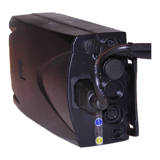
Page 24: Type Label
User Manual LogicSP-2-1 / LogicSP-2-2 5.3. Type Label The following figure illustrates the type of information found on the type label and its location on the control box. Note: Specifications on your LogicSP motor control box vary depending on the version of the device and its firmware revision. -
Page 25: Appendix
User Manual LogicSP-2-1 / LogicSP-2-2 6. Appendix This chapter offers information on: Possible problems and standard solutions. • Error messages. (Displayed error messages.) • Optional products useable with the LogicSP motor control. • Plus: A drill-template to speed up the installation procedure of the motor control. -
Page 26: Error Messages
In the absence of a handset with integrated display, these messages can be viewed using a software program such as the LiftBox™ Diagnostic Tool by LOGICDATA. The remainder of this section uses the appearance of these error messages on a standard LOGICDATA handset with integrated display for illustration purposes. -
Page 27: Optional Accessories
6.3. Optional Accessories LOGICDATA offers a wide range of optional accessories. Please contact your supplier to get a detailed product catalogue. As a rule of thumb, most accessories compatible with the LogicS motor control will also work with the LogicSP motor control. -
Page 28: Drill Template
User Manual LogicSP-2-1 / LogicSP-2-2 6.4. Drill Template To speed up installation of the LogicSP motor control, print this page on A4 paper and cut out this drill template to mark the drill holes for mounting the control box. Fig. 12 – Drill Template... -
Page 29: Continuitive Information
User Manual LogicSP-2-1 / LogicSP-2-2 7. Continuitive Information 7.1. Final Disposal Heed following disposal instructions when disposing of the LogicSP motor control box: Note: Dispose of the components ecologically sound (separate plastic from electronics parts)! This applies to components like squeeze line, drives, cables, etc. as well! 7.2.
Need help?
Do you have a question about the LogicSP-2-1 and is the answer not in the manual?
Questions and answers