Table of Contents
Advertisement
User Manual
Motor Control for Height Adjustable Desks
LogicS-2 / LogicS-3
LOGICDATA Electronic & Software Entwicklungs GmbH
Hinterleitenstrasse 22a
A 8523 Frauental /Austria
Version: 3
Availability and specifications are subject to change without prior notice. LOGICDATA assumes no
liability for maloperation or improper use of products. LOGICDATA will at point of delivery
replace/repair defective products covered by the warranty. No liability is assumed beyond such
replacement/repair. Please contact LOGICDATA directly on inquiries or custom requirements.
2004 LOGICDATA
Advertisement
Table of Contents

Related Manuals for LOGICDATA LogicS-2


Summary of Contents for LOGICDATA LogicS-2
- Page 1 Availability and specifications are subject to change without prior notice. LOGICDATA assumes no liability for maloperation or improper use of products. LOGICDATA will at point of delivery replace/repair defective products covered by the warranty. No liability is assumed beyond such replacement/repair.
-
Page 2: Table Of Contents
Appropriate Operation....................4 1.2. Functionality LogicS-2 / LogicS-3................4 1.3. Audience and Previous Knowledge ................5 1.4. Performance Differences LogicS-2 / LogicS-3............5 1.5. Safety Instruction Symbols ..................5 1.6. ISP – Intelligent System Protection ................6 1.7. Package Contents ....................... 7 1.8. - Page 3 User Manual LogicS-2 / LogicS-3 7. Continuative Information ..................... 33 Final Disposal......................33 Manufacturer's Data ....................33 Page 3/33...
-
Page 4: Preface
1.1. Appropriate Operation LogicS-2 / LogicS-3 – motor control boxes must solely be used for the intended application, control of height-adjustable desks. Only motors which meet the specifications of LOGICDATA GmbH must be used to drive lifting columns. The control box must be installed, initially operated and functional tested by competent personnel only. -
Page 5: Audience And Previous Knowledge
• Lecture of this manual 1.4. Performance Differences LogicS-2 / LogicS-3 LogicS-2 The motor control box LogicS-2 is suitable to control up to 2 motors for desk height adjustment. LogicS-3 The motor control box LogicS-3 is suitable to control up to 3 motors for desk height adjustment. -
Page 6: Isp - Intelligent System Protection
Note: Note the commitment to read the user manual! 1.6. ISP – Intelligent System Protection ISP is a state-of-the-art protection system developed by LOGICDATA. With ISP, a possible bruise hazard is significantly decreased. Danger: However, in exceptional cases a certain bruise hazard may be... -
Page 7: Package Contents
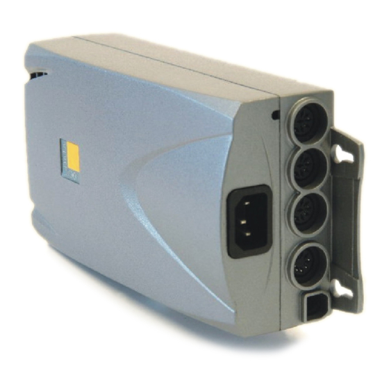
User Manual LogicS-2 / LogicS-3 1.7. Package Contents The LogicS control box package contains: Fig. 1 - Package Contents LogicS control box with mounting link Mounting plate Mains cable Note: For detailed information on optional control components and accessories, see page 30! 1.8. -
Page 8: Safety Instructions
User Manual LogicS-2 / LogicS-3 1.9. Safety Instructions This user manual contains safety instructions to point out possible dangers and therefore allow a safe operation of the LogicS control box. Please consider these safety instructions unconditionally! Within this chapter you will find general safety instructions, which do not refer to a particular procedure. -
Page 9: Important Service Note
User Manual LogicS-2 / LogicS-3 Danger: To prevent fire or shock hazard, do not expose this device to rain or moisture! Danger: When operating the motor drive take care not to pinch individuals or objects! Even with activated protection systems a certain... -
Page 10: Mounting Instructions Logics
User Manual LogicS-2 / LogicS-3 2. Mounting Instructions LogicS Mount the LogicS motor control on the bottom surface of the desk top. Following tools are needed for installation: • 1 screw driver for recessed head screws • 1 pencil • 1 drill machine(to pre-drill the holes) •... - Page 11 User Manual LogicS-2 / LogicS-3 6. Fix the mounting plate with 2 screws in the pre-drilled holes. Fig.3 - Step 6 Note: Note the V formation of the mounting plate (see fig. 3)! 7. Slide the LogicS control box onto the mounting plate so it is fully inserted in the control box housing.
- Page 12 User Manual LogicS-2 / LogicS-3 9. Detach the control box again. 10. Pre-dril these 2 holes. 11. Screw-in the remaining 2 screws halfway into the 2 drill holes. Fig.6 - Step 11 12. Attach the control box again. 13. Slide the LogicS control box onto the mounting plate again so it is fully inserted in the control box housing.
-
Page 13: Initial Operation
User Manual LogicS-2 / LogicS-3 3. Initial Operation The initial operation consists of the necessary steps to make a height- adjustable desk actually height adjustable with the LogicS motor control. Prerequisites are: • The LogicS control box is mounted (according to the instructions in chapter 2). -
Page 14: Initial Operation Procedure
Note: When connecting, strictly stick to the sequence M1, M2, M3! 3.2.2. Connect Handset Connect the handset to the 7-pin DIN socket (HS). Note: You may connect any LOGICDATA handset to the LogicS control box! 3.2.3. Connect Optional Components If your LogicS control box has a grounding cable, mount it to a metal part of the desk. -
Page 15: System Configuration (Example)
User Manual LogicS-2 / LogicS-3 3.2.5. System Configuration (Example) The following figure illustrates the interface connections of an example configuration. This example configuration consists of: 1 LogicS-3 control box 3 Motor drives (hidden in the table-legs) Handset HSU-MDF-4F2-LD 1 Squeeze line Fig.9 –... -
Page 16: Operating The Logics Control Box
User Manual LogicS-2 / LogicS-3 4. Operating the LogicS Control Box To ensure safe operation of the LogicS control box, observe following safety instructions: Caution: Keep children away from height-adjustable desks, control boxes and handsets! Risk of electric shock may be present. -
Page 17: Advanced Functionality
User Manual LogicS-2 / LogicS-3 4.2 Advanced Functionality Note: Functionality described in this chapter is only accessible if you have a handset with position keys and a save key! 4.2.1. Saving a Position This function allows to save one desk-height per position key. To save a desk... -
Page 18: Moving To A Saved Position
User Manual LogicS-2 / LogicS-3 4.2.2. Moving to a Saved Position This function allows to move the desk to a saved position. To move to a saved position, proceed as follows: Note: Whether the double-click automatic function is available or not, depends on the software configuration of the control box. -
Page 19: Change Displayed Height
User Manual LogicS-2 / LogicS-3 4.2.3. Change Displayed Height This function allows you to change the displayed height, you cannot change the desk-height with this function. Proceed as follows: Press the S key. The display reads S –. Press and hold key desk down (arrow downwards) for appr. -
Page 20: Activation Of The End Position Alignment Procedure
User Manual LogicS-2 / LogicS-3 4.2.5. Activation of the End Position Alignment Procedure Activating the end position alignment procedure lies within the scope of initial operation carried out by a service technician. Note: Whether the "S7" function is available or not depends on the configuration of the control box. - Page 21 User Manual LogicS-2 / LogicS-3 Press key T2 to decrease the displayed height (driving in any direction is locked). Press the S key. 088 is flashing on the display. Press and hold key desk up until the desk has reached the upper end position.
-
Page 22: Software-Dependent Functions
User Manual LogicS-2 / LogicS-3 4.3 Software-dependent Functions Note: Prior to delivery, the LogicS control box is being parameterized. Following functions are only available if the control box is parameterized accordingly. 4.3.1. Reset after Power On After each power-on (e.g. connecting the power cord) following reset... -
Page 23: Pin Code
User Manual LogicS-2 / LogicS-3 Note: The range of variation that is applied to the saved positions is software-configurable. 4.3.5. PIN Code The handset can be locked with the PIN code function. Therefore, handset functionality is deactivated (e.g. move to saved height position, store new height position, etc.) -
Page 24: Safety Area
Furthermore, stopping sensitivity is being influenced by mechanical components, ambient conditions and the motor activity! Therefore, LOGICDATA, as the control box manufacturer, cannot completely eliminate this risk and we point out that we cannot be held liable in the case of maloperation! -
Page 25: Auto Detect Number Of Drives
User Manual LogicS-2 / LogicS-3 4.3.9. Auto Detect Number of Drives In the course of the reset procedure, the number of drives is being checked. The control box automatically reconfigures itself to the number of detected drives. 4.3.10. Duty Cycle Monitoring The duty cycle monitoring function forces the control box to stop after a certain on-time is exceeded (e.g. -
Page 26: Technical Data
User Manual LogicS-2 / LogicS-3 5. Technical Data General ± Supply Voltage 110V 6% / 60 Hz Standby-Consumption primary 1,1 W ± Operating Voltage Electronics 5VDC 5% 150mA ± Hall Sensor Operating Voltage 5VDC 10% 150mA Ambient Temperature 0 - 35°C Operation Humidity 5 –... - Page 27 User Manual LogicS-2 / LogicS-3 off) Switching Capacity 5% (30 sec on / 9:30 360VA / 13A / 28V @ 25°C min off) Switching Capacity 10% (1 min on / 9 min 13A upwards, 2A downwards off) Weight 2,1 kg...
- Page 28 User Manual LogicS-2 / LogicS-3 Fig.11 – Type label Page 28/33...
-
Page 29: Appendix
User Manual LogicS-2 / LogicS-3 6. Appendix This chapter offers detailed information on the following topics: • Possible troubles and solutions • Displayed error messages • Optional products (squeeze line and handsets) • Drill template 6.1 Possible Troubles and Solutions... -
Page 30: Displayed Error Messages
User Manual LogicS-2 / LogicS-3 6.2 Displayed Error Messages The display reads HOT. Cause Solution The LogicS control box is Wait until the control box has cooled equipped with overtemperature down and the displyed HOT goes out. protection. This protection... -
Page 31: Optional Accessories
User Manual LogicS-2 / LogicS-3 6.3 Optional Accessories LOGICDATA offers a wide range of optional accessories. Please contact your supplier to get a detailed product catalog. Page 31/33... -
Page 32: Drill Template
User Manual LogicS-2 / LogicS-3 6.4 Drill Template Cut out this drill template and mark the drill holes on the desk top. Page 32/33... - Page 33 User Manual LogicS-2 / LogicS-3 7. Continuative Information 7.1 Final Disposal Heed following disposal instructions when disposing of the LogicS control box: Note: Dispose of the components ecologically sound (separate plastic from electronics parts)! Same applies to components like squeeze line, drives, cables, etc.! 7.2 Manufacturer's Data...
Need help?
Do you have a question about the LogicS-2 and is the answer not in the manual?
Questions and answers