Metrohm 917 Coulometer Manual - Short Instructions
Hide thumbs
Also See for 917 Coulometer:
- Tutorial (67 pages) ,
- Manual (338 pages) ,
- Manual - short instructions (35 pages)
Table of Contents
Advertisement
Quick Links
Advertisement
Table of Contents

Subscribe to Our Youtube Channel
Related Manuals for Metrohm 917 Coulometer


Summary of Contents for Metrohm 917 Coulometer
- Page 1 917 Coulometer Manual – Short Instructions 8.917.8002EN / 2019-11-20...
- Page 3 Metrohm AG CH-9100 Herisau Switzerland Phone +41 71 353 85 85 Fax +41 71 353 89 01 info@metrohm.com www.metrohm.com 917 Coulometer Manual – Short Instructions 8.917.8002EN / 2019-11-20...
- Page 4 Technical Communication Metrohm AG CH-9100 Herisau techcom@metrohm.com This documentation is protected by copyright. All rights reserved. This documentation has been prepared with great care. However, errors can never be entirely ruled out. Please send comments regarding possible errors to the address above.
-
Page 5: Table Of Contents
Connecting indicator electrodes ..........19 5.4.3 Connecting a temperature sensor .......... 21 Connecting MSB devices ............ 22 5.5.1 Connecting a dosing device ........... 23 5.5.2 Connecting an additional stirrer or titration stand ....24 5.5.3 Connecting a Remote Box ............. 24 ■■■■■■■■ 917 Coulometer... - Page 6 Switching the instrument on and off ........ 29 Fundamentals of operation ..........31 6.2.1 Touch-sensitive screen ............31 6.2.2 Display elements and controls ..........32 6.2.3 Status display ................. 33 6.2.4 Entering text and numbers ............. 34 7 Maintenance Index ■■■■■■■■ 917 Coulometer...
- Page 7 Unscrewing the protective cap from the indicator electrode .... 19 Figure 12 Screwing the electrode cable to the indicator electrode ....20 Figure 13 Connecting an indicator electrode ........... 20 Figure 14 MSB connections ................22 Figure 15 MSB connector ................23 ■■■■■■■■ 917 Coulometer...
-
Page 9: About These Short Instructions
1 About these short instructions This short instruction manual contains important information concerning the 917 Coulometer. In addition to an introduction, safety instructions and an overview of the instrument, you will also find information about the installation of the coulometer. -
Page 10: Introduction
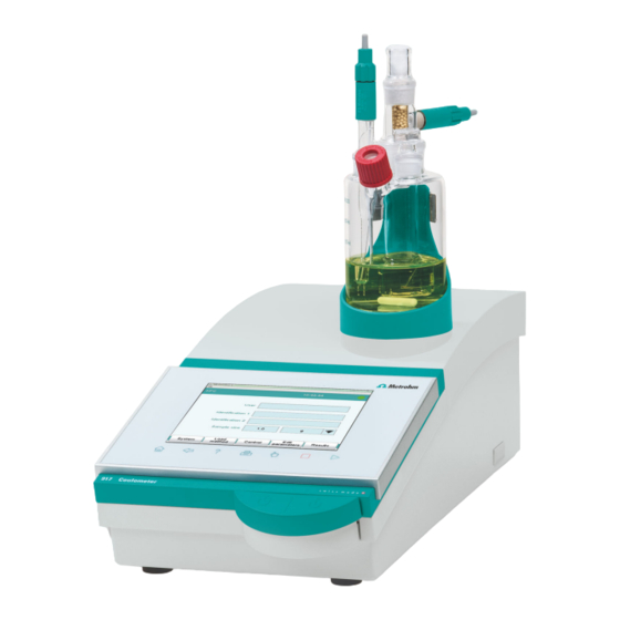
The upper side of the housing offers space for the titration cell. Thanks to its compact construction, you can use the 917 Coulometer in a small space as a stand-alone titrator. -
Page 11: Connectors
For connecting tubing for replacing reagent using the built-in pump. 2.1.3 Intended use The 917 Coulometer is designed for usage as a titrator in analytical labora- tories. Its main application field is coulometric Karl Fischer titration. This instrument is suitable for processing chemicals and flammable sam- ples. -
Page 12: Symbols And Conventions
WARNING This symbol draws attention to a possible biological hazard. CAUTION This symbol draws attention to possible damage to instruments or instrument parts. NOTE This symbol highlights additional information and tips. ■■■■■■■■ 917 Coulometer... -
Page 13: Safety Instructions
The electrical safety when working with the instrument is ensured as part of the international standard IEC 61010. WARNING Only personnel qualified by Metrohm are authorized to carry out service work on electronic components. WARNING Never open the housing of the instrument. The instrument could be damaged by this. -
Page 14: Tubing And Capillary Connections
Set up the instrument in a well-ventilated location (e.g. fume cup- ■ board). Keep all sources of flame far from the workplace. ■ Clean up spilled liquids and solids immediately. ■ Follow the safety instructions of the chemical manufacturer. ■ ■■■■■■■■ 917 Coulometer... -
Page 15: Recycling And Disposal
The correct disposal of your old instrument will help to prevent negative effects on the environment and public health. More details about the disposal of your old instrument can be obtained from your local authorities, from waste disposal companies or from your local dealer. ■■■■■■■■ 917 Coulometer... -
Page 16: Overview Of The Instrument
Fixed key [STOP] 10 Fixed key [START] Cancels the running determination. Starts a determination. 11 Magnetic stirrer For placing the titration vessel holder. ■■■■■■■■ 917 Coulometer... -
Page 17: Rear Of The Instrument
For connecting temperature sensors (Pt1000 or NTC). Two B sockets, 2 mm. MSB connector (MSB 1 and MSB 2) Generator electrode connector (Gen.) Metrohm Serial Bus. For connecting external For connecting the generator electrode. dosing devices, stirrers or a Remote Box. Mini DIN, 8-pin. -
Page 18: Installation
Place the instrument in a location of the laboratory which is suitable for operation and free of vibrations and which provides protection against corrosive atmosphere and contamination by chemicals. The instrument should be protected against excessive temperature fluctua- tions and direct sunlight. ■■■■■■■■ 917 Coulometer... -
Page 19: Setting Up The Titration Cell For Coulometry
2 Insert the 6.1464.320 titration cell into the titration vessel holder. 5.2.2 Preparing the titration cell Filling the adsorber tube Before setting up the titration cell, the 6.1403.030 adsorber tube has to be filled with 6.2811.000 molecular sieve. Proceed as follows: ■■■■■■■■ 917 Coulometer... -
Page 20: Figure 4 Filling The Adsorber Tube
4 Seal the adsorber tube with the appropriate cover. NOTICE Note that the molecular sieve must be replaced at regular intervals. Each time you refill the adsorber tube with molecular sieve, you can, for example, write the date directly on the adsorber tube. ■■■■■■■■ 917 Coulometer... -
Page 21: Figure 5 Equipping The Titration Cell
Take care to ensure that the edges of the ground-joint sleeves are cut to size cleanly and that there are no fringes. The ground-joint sleeves must not protrude at the lower edge of the ground-joint opening. 3 Insert the 6.1403.030 adsorber tube into the generator electrode. ■■■■■■■■ 917 Coulometer... - Page 22 6.2738.000 funnel. The level of the anolyte should be roughly 1 to 2 mm above the level of the catholyte. 3 Close the remaining ground-joint opening on the right with the 6.1437.000 ground-joint stopper (with ground-joint sleeve attached). ■■■■■■■■ 917 Coulometer...
-
Page 23: Mounting The Addition And Aspiration Tube
6 Connect the tubing for the aspiration of the titration cell at the lower connector of the addition and aspiration tube (6). Details regarding how to connect the addition tubing and the aspiration tubing can be found in the tutorial for the 917 Coulometer. ■■■■■■■■ 917 Coulometer... -
Page 24: Connecting The Coulometer To The Power Supply
5.3 Connecting the coulometer to the power supply Connecting the coulometer to the power supply Connecting the power supply unit The 917 Coulometer has an external power supply unit for a 24 V power supply (DC). This is connected to the power socket of the coulometer. WARNING An incorrect supply voltage can damage the instrument. -
Page 25: Connecting Sensors
Mark the screw heads of the cables accordingly. 5.4.1 Connecting generator electrodes Screwing the electrode cable to the generator electrode 1 Unscrew the protective cap from the generator electrode. ■■■■■■■■ 917 Coulometer... -
Page 26: Figure 8 Unscrewing The Protective Cap From The Generator Electrode
2 Tighten the 6.2104.120 electrode cable to the generator electrode. 6.2104.120 Figure 9 Screwing the electrode cable to the generator electrode Connecting the electrode cable to the coulometer 1 Plug the electrode plug into the Gen. socket of the coulometer. ■■■■■■■■ 917 Coulometer... -
Page 27: Connecting Indicator Electrodes
Screwing the electrode cable to the indicator electrode 1 Unscrew the protective cap from the indicator electrode. Figure 11 Unscrewing the protective cap from the indicator elec- trode 2 Tighten the 6.2104.020 electrode cable to the indicator electrode. ■■■■■■■■ 917 Coulometer... -
Page 28: Figure 12 Screwing The Electrode Cable To The Indicator Electrode
5.4 Connecting sensors 6.2104.020 Figure 12 Screwing the electrode cable to the indicator electrode Connecting the electrode cable to the coulometer 1 Plug the electrode plug into the Ind. socket of the coulometer. Figure 13 Connecting an indicator electrode ■■■■■■■■ 917 Coulometer... -
Page 29: Connecting A Temperature Sensor
1 Insert the plugs of the temperature sensor into the Temp. sockets of the coulometer. NOTICE Always insert the red plug into the red socket. This is the only way that shielding against electrical interference can be ensured. ■■■■■■■■ 917 Coulometer... -
Page 30: Connecting Msb Devices
Connecting MSB devices In order to connect MSB devices, e.g. dosing devices or Remote Box, the Coulometer has two connectors to what is referred to as the Metrohm Serial Bus (MSB). Various peripheral devices can be connected in sequence (daisy chain) at a single MSB connector (8-pin Mini DIN socket) and be controlled simultaneously by the Coulometer. -
Page 31: Connecting A Dosing Device
MSB connections can be extended with the 6.2151.010 cable. The maxi- mum connection length permitted is 6 m. 5.5.1 Connecting a dosing device You can connect two dosing devices to the Coulometer. The types of dosing devices that are supported are: 800 Dosino ■ 805 Dosimat ■ ■■■■■■■■ 917 Coulometer... -
Page 32: Connecting An Additional Stirrer Or Titration Stand
Instruments that are controlled via remote lines and/or that send control signals via remote lines can be connected via the 6.2148.010 Remote Box. In addition to Metrohm, other instrument manufacturers also use similar connectors that make it possible to connect different instruments together. -
Page 33: Connecting Usb Devices
Connecting USB devices 5.6.1 General The 917 Coulometer has a USB connector (Type A socket) for peripheral devices with USB interface. If you wish to connect more than one device to the USB, you can use a commercially available USB hub. -
Page 34: Connecting A Balance
ME 46278 foot switch Ohaus Voyager, Explorer, Analyti- Cable AS017-09 from Ohaus cal Plus Precisa balances with RS-232-C 6.2125.080 + 6.2125.010 interface Sartorius MP8, MC, LA, Genius, 6.2134.060 Cubis Shimadzu BX, BW 6.2125.080 + 6.2125.010 ■■■■■■■■ 917 Coulometer... -
Page 35: Connecting A Pc Keyboard
The barcode reader is used as an aid for text and numerical input. You can connect a barcode reader with USB interface. Connect the barcode reader as follows: 1 Connect the USB plug of the barcode reader with the USB connector of the Coulometer (Type A). ■■■■■■■■ 917 Coulometer... -
Page 36: Connecting The Coulometer To A Network
6 Exit the programming mode. Connecting the Coulometer to a network The 917 Coulometer has a network connection (Ethernet). This can be used to integrate your Coulometer in your network. You can, for example, store data on a PC within the network or print reports on a network printer. -
Page 37: Operation
Selecting the dialog language of the detailed manual. Proceed as follows: Press the power switch on the left-hand side of the back panel of ■ the 917 Coulometer. The 917 Coulometer is initialized. A system test is performed. This process takes some time. ■■■■■■■■ 917 Coulometer... - Page 38 Switching off the instrument CAUTION The 917 Coulometer must be switched off by pressing the power switch on the rear of the instrument before the electricity supply is interrupted. If this is not done, then there is a danger of data loss.
-
Page 39: Fundamentals Of Operation
You can always return to the main dialog by touching [ In order to activate an element on the 917 Coulometer user interface, just touch the screen with your fingertip, finger nail, the eraser of a pencil or a stylus (special tool for operating instruments with touch-sensitive screens). -
Page 40: Display Elements And Controls
In the other dialogs, the title bar shows the headings of the next upper level and of the displayed dialog. This is an aid for orientation during navi- gation through the user dialog. Table 2 Screen elements Buttons open a new dialog when they are tap- ped. ■■■■■■■■ 917 Coulometer... -
Page 41: Status Display
The instrument is in normal status. The working medium is being conditioned. Conditioning has been paused. The working medium is conditioned. A method has been started. A method has been paused. An action has been started in manual control. ■■■■■■■■ 917 Coulometer... -
Page 42: Entering Text And Numbers
[A…Z]. The upper-case letters are displayed again by tapping. [0…9] Numbers and mathematical characters are dis- played. [Special charac- Special characters are displayed. You can use the ters] button [More] to navigate through all available characters. ■■■■■■■■ 917 Coulometer... - Page 43 You can select the result variable by touching [R1]. NOTICE A commercially available USB keyboard can be connected to make text and numerical input easier. ■■■■■■■■ 917 Coulometer...
-
Page 44: Maintenance
Maintenance The electronic and mechanical functional groups of Metrohm instruments can and should be checked by specialist personnel from Metrohm as part of a regular preventive maintenance schedule. Please ask your local Metrohm representative regarding the precise terms and conditions involved in concluding a corresponding maintenance agreement. - Page 45 Dosing device ..... 23 MSB devices ....... 22 Metrohm Serial Bus ....9 Temperature sensor ....9, 21 PC keyboard ....... 27 Metrohm Serial Bus MSB, see also Connect ......17 Printer ........ 25 "MSB" ........22 Text input ......... 34 Remote Box ......
Need help?
Do you have a question about the 917 Coulometer and is the answer not in the manual?
Questions and answers