Table of Contents
Advertisement
Advertisement
Table of Contents

Related Manuals for Metrohm NIRS DS2500


Summary of Contents for Metrohm NIRS DS2500
- Page 1 NIRS DS2500 Analyzer Manual 8.922.8001EN / 2014-07-10...
- Page 3 Metrohm AG CH-9100 Herisau Switzerland Phone +41 71 353 85 85 Fax +41 71 353 89 01 info@metrohm.com www.metrohm.com NIRS DS2500 Analyzer Manual 8.922.8001EN / 2014-07-10...
- Page 4 Teachware Metrohm AG CH-9100 Herisau teachware@metrohm.com This documentation is protected by copyright. All rights reserved. Although all the information given in this documentation has been checked with great care, errors cannot be entirely excluded. Should you notice any mistakes please send us your comments using the address given above.
-
Page 5: Table Of Contents
Inserting the sample cup for granulated substances ....15 3.7.2 Inserting the sample cup for powders ........16 3.7.3 Inserting the sample cup for liquid samples ......17 4 Control 5 Operation 6 Maintenance Maintenance by Metrohm Service ........20 ■■■■■■■■... - Page 6 ■■■■■■■■■■■■■■■■■■■■■■ Table of contents User maintenance ............... 20 6.2.1 Replacing the lamp ..............20 6.2.2 Replacing the fan filter ............28 6.2.3 Replacing the fuses ..............30 7 Troubleshooting Malfunction during start-up ..........32 Error messages from the software ........32 8 Technical specifications Interfaces ................
- Page 7 ■■■■■■■■■■■■■■■■■■■■■■ Table of figures Table of figures Figure 1 Front NIRS DS2500 Analyzer .............. 5 Figure 2 Rear NIRS DS2500 Analyzer ............... 6 ■■■■■■■■...
-
Page 9: Introduction
■ Liquid samples: liquids or suspensions ■ The NIRS DS2500 Analyzer is a robust instrument that is resistant to mois- ture, dust, vibrations and temperature fluctuations. As a result, it can be operated in a variety of production facilities. The NIRS DS2500 Analyzer is operated with the Vision software via an external computer. -
Page 10: Intended Use
■■■■■■■■■■■■■■■■■■■■■■ 1.2 Intended use Intended use The NIRS DS2500 Analyzer is designed for use in production facilities. It can be used for incoming goods inspection or atline for production pro- cess monitoring. This instrument is suitable for measuring chemicals and flammable sam- ples. -
Page 11: Safety Instructions
1.4.2 Electrical safety The electrical safety when working with the instrument is ensured as part of the international standard IEC 61010. WARNING Only personnel qualified by Metrohm are authorized to carry out service work on electronic components. ■■■■■■■■... -
Page 12: Flammable Solvents And Chemicals
■■■■■■■■■■■■■■■■■■■■■■ 1.4 Safety instructions WARNING Never open the housing of the instrument. The instrument could be damaged by this. There is also a risk of serious injury if live components are touched. There are no parts inside the housing which can be serviced or replaced by the user. -
Page 13: Overview Of The Instrument
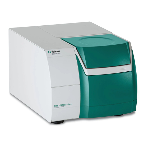
■■■■■■■■■■■■■■■■■■■■■■ 2 Overview of the instrument 2 Overview of the instrument Front Figure 1 Front NIRS DS2500 Analyzer Cover Sampling window LED display Lamp compartment Feet (shock-absorbing) ■■■■■■■■... -
Page 14: Rear
■■■■■■■■■■■■■■■■■■■■■■ 2.2 Rear Rear Figure 2 Rear NIRS DS2500 Analyzer On/off switch Fuse holder For switching the instrument on and off. Power socket Type plate Sealed with protective cap. LAN connection socket Sealed with protective cap. With filter. ■■■■■■■■... -
Page 15: Installation
3.1.3 Scope of application The NIRS DS2500 Analyzer is designed for offline use in the laboratory or atline use in the production process. Setting up the instrument Like most high-precision instruments, the NIRS DS2500 Analyzer is sensi- tive to ambient conditions, which may negatively influence its perfor- mance and shorten its service life. -
Page 16: General Conditions
Vibrations and shocks interfere with the sensitive optical and mechanical components and compromise calibration and measuring accuracy. Set up the NIRS DS2500 Analyzer at a stable workplace that does not propagate vibrations resulting from manual work (e.g. typing on the com- puter keyboard). - Page 17 ■■■■■■■■■■■■■■■■■■■■■■ 3 Installation 3 Plug the cable of the power supply unit into the power socket and tighten it. 4 Plug the power supply cable into the socket of the power supply unit. 5 Connect the other end of the power supply cable to the power sup- ply.
-
Page 18: Connecting The Data Cable
■■■■■■■■■■■■■■■■■■■■■■ 3.4 Connecting the data cable Connecting the data cable To be controlled, the NIRS DS2500 Analyzer is connected to a computer either directly or via a local network (LAN). Use the supplied crossover data cable for connecting the instrument directly to a computer's network card. -
Page 19: Switching On The Instrument
Switching on the instrument Switching on the instrument 1 Turn the on/off switch to the position I. The LED display on the front of the NIRS DS2500 Analyzer (1-3) ■ lights up. The instrument performs a self-test. ■... -
Page 20: Initial Start-Up
This manual contains a short overview of the required steps. You can find detailed information on the procedure in the tutorial for the software. Non-regulated indus- If you put the NIRS DS2500 Analyzer into operation in a non-regulated tries industry, carry out the following steps: Switch on the computer. - Page 21 ■■■■■■■■■■■■■■■■■■■■■■ 3 Installation The metal pin on the sample cup holder must go into the indentation on the sampling window. In the software, start Wavelength Certification. Follow the ■ instructions in the software. When the software prompt appears, insert the wavelength stan- ■...
- Page 22 Remove the reflection standard from the holder. ■ Regulated industries If you put the NIRS DS2500 Analyzer into operation in a regulated indus- try, then additional tests are required after the procedures described in the chapter "Non-regulated industries" have been performed.
-
Page 23: Setting Up Accessories
■■■■■■■■■■■■■■■■■■■■■■ 3 Installation Setting up accessories Metrohm supplies various sample cups for your NIRS DS2500 Analyzer: Samples Sample cups Order number Solid samples, powders NIRS mini sample cups, 10 pcs., incl. 100 dis- 6.7402.030 posable backs Solid samples, granulated substances NIRS DS2500 large sample cup 6.7402.050... -
Page 24: Inserting The Sample Cup For Powders
Inserting the sample cup for powders Required accessories NIRS DS2500 mini sample cup (6.7402.030) ■ NIRS DS2500 holder for sample cup (6.7430.040) ■ 1 Clean the sample cup and the sampling window with a lens cleaner cloth. Fill the powder into the sample cup. -
Page 25: Inserting The Sample Cup For Liquid Samples
Inserting the sample cup for liquid samples Required accessories NIRS liquid sample kit transflection (6.7400.010) ■ NIRS DS2500 holder for sample cup (6.7430.040) ■ 1 Clean the sample cup and the sampling window with a lens cleaner cloth. Fill liquid sample to a height of approx. 1 cm into the sample cup. -
Page 26: Control
■■■■■■■■■■■■■■■■■■■■■■ 4 Control The NIRS DS2500 Analyzer is operated with the Vision software. You can find more information on working with the software in the tuto- rial for the software. ■■■■■■■■... -
Page 27: Operation
■■■■■■■■■■■■■■■■■■■■■■ 5 Operation 5 Operation The NIRS DS2500 Analyzer requires appropriate care. Excess contamina- tion of the instrument may result in functional disruptions and may reduce the service life of the essentially robust mechanics and electronics. Clean the sampling window and the accessory parts only with lens cleaner cloths. -
Page 28: Maintenance
6 Maintenance Maintenance by Metrohm Service Maintenance of the NIRS DS2500 Analyzer is best carried out as part of annual service, which is performed by specialist personnel from Metrohm. A shorter maintenance interval may be necessary if you frequently work with caustic and corrosive chemicals. - Page 29 Remove the lamp with appropriate care. ■ NOTE Spare part A new spare lamp is available from your Metrohm representative under the article number 6.7430.050. We recommend keeping spare lamps in stock. ■ Use only original lamps in the instrument.
- Page 30 ■■■■■■■■■■■■■■■■■■■■■■ 6.2 User maintenance 3 Removing the lamp holder Push the white lamp holder approx. 2 mm inwards, ■ then turn it about 45° counterclockwise and ■ then carefully pull it out straight. ■ Place the lamp on the cover with the reflector facing down. ■...
- Page 31 ■■■■■■■■■■■■■■■■■■■■■■ 6 Maintenance 4 Disconnecting the cables CAUTION Functional disruption Do not loosen the screw terminals of the black cables. Loosen only the screw terminals of the white cables. Loosen the screw terminals of the white cables using a small ■...
- Page 32 ■■■■■■■■■■■■■■■■■■■■■■ 6.2 User maintenance 5 Removing the lamp from the holder Hold the lamp by the reflector. ■ Lift the lamp holder off the lamp and the cables. ■ TIP: Bend the cables to mark the lamp as used. Installing a new lamp Required accessories Spare lamp (6.7430.050) ■...
- Page 33 ■■■■■■■■■■■■■■■■■■■■■■ 6 Maintenance CAUTION Damage to the lamp Fingerprints and greasy deposits may damage the lamp. Do not touch the glass part of the lamp or the inner side of the reflec- tor. 1 Keeping the new lamp ready Take the new lamp out of the packaging. ■...
- Page 34 ■■■■■■■■■■■■■■■■■■■■■■ 6.2 User maintenance Guide the lamp cables through the rectangular opening of the ■ lamp holder. Place the lamp holder onto the lamp's reflector. The spring on the ■ lamp holder keeps the lamp in the correct position. 3 Connecting the lamp cables Push the two white cables all the way into the corresponding ■...
-
Page 35: Calibrating The Instrument
■■■■■■■■■■■■■■■■■■■■■■ 6 Maintenance 4 Inserting the lamp holder First, push the white lamp holder carefully all the way into the ■ opening, then turn it approx. 45° clockwise and ■ then slowly let it go. ■ 5 Closing the lamp compartment Place the sealing plate onto the opening. -
Page 36: Replacing The Fan Filter
■■■■■■■■■■■■■■■■■■■■■■ 6.2 User maintenance 6.2.2 Replacing the fan filter The fan filter has to be checked at least once a month. If the instrument is operated in a dusty or otherwise dirty environment, then a check is required once or even twice a week. The fan is located on the rear of the instrument. - Page 37 ■■■■■■■■■■■■■■■■■■■■■■ 6 Maintenance 4 Cleaning the filter Blow out the dirty filter with a compressed air duster spray. ■ Alternative: Rinse the dirty filter with clean water and allow to dry. ■ 5 Mounting the filter Place the new or cleaned filter symmetrically into the filter cover. The filter must not be wrinkled or folded.
-
Page 38: Replacing The Fuses
■■■■■■■■■■■■■■■■■■■■■■ 6.2 User maintenance 6.2.3 Replacing the fuses The fuse is located on the rear of the instrument, directly underneath the on/off switch. Required accessories Spare fuse, type: 250 V, 5 A, slow-acting fuse, 20 mm ■ 1 Switching off the instrument Turn the on/off switch (2-1) to the position O. - Page 39 ■■■■■■■■■■■■■■■■■■■■■■ 6 Maintenance 3 Inserting the new fuse Insert a new fuse of the same type into the holder. ■ Place the fuse holder back into the opening on the rear of the ■ instrument and tighten by hand. 4 Switching on the instrument Plug the power supply cable back in.
-
Page 40: Troubleshooting
■■■■■■■■■■■■■■■■■■■■■■ 7.1 Malfunction during start-up 7 Troubleshooting Malfunction during start-up Problem Cause Remedy The instrument does The power supply cable is Correctly connect the power supply cable (see not start. not or incorrectly con- "Connecting the power supply cable", page nected. -
Page 41: Technical Specifications
■■■■■■■■■■■■■■■■■■■■■■ 8 Technical specifications 8 Technical specifications Interfaces Ethernet connec- Ethernet connector for data transmission to a PC tion socket Power connection Nominal voltage 100 to 240 V ± 10% (autosensing) range Frequency 50 and 60 Hz (autosensing) Fuse Diameter 5 mm, length 20 mm 250 V, 5 A (slow-acting) Ambient conditions Temperature... -
Page 42: Safety Specifications
■■■■■■■■■■■■■■■■■■■■■■ 8.5 Safety specifications Wavelength preci- sion Based on one < 0.005 nm instrument Based on an < 0.02 nm instrument group Photometric noise 400 to 700 nm < 50 mAU 700 to 2,500 < 20 mAU Safety specifications This instrument fulfills the following electrical safety requirements: CE marking in accordance with the EU directives: 2006/95/EC (Low Voltage Directive, LVD) ■... -
Page 43: Dimensions
■■■■■■■■■■■■■■■■■■■■■■ 8 Technical specifications Dimensions Dimensions Length 490 mm Width 375 mm Height 300 mm (closed) 534 mm (opened) Weight 27 kg Additional free at least 100 mm (on the sides and rear) space ■■■■■■■■... -
Page 44: Warranty (Guarantee)
■■■■■■■■■■■■■■■■■■■■■■ 9 Warranty (guarantee) Metrohm guarantees that the deliveries and services it provides are free of defects in materials, design or manufacturing. The general warranty period is 36 months (exclusions below) from the date of delivery, or 18 months in the event of continuous operation. The... - Page 45 This does not apply for software products sold under the Metrohm NIRSystems brand. If Metrohm AG is unable to meet this obligation due to circumstances beyond the control of Metrohm AG, then the ordering party shall be offered alternative solutions at preferential conditions.
-
Page 46: Accessories
The search results will be displayed. 4 In the search results, select the Devices tab (if it is not already selected) and then click on the Metrohm article number of the required instrument (e.g. 2.852.0050). The page with information pertaining to the searched article is dis- played. - Page 47 Downloading the accessories list 1 Type http://partslists.metrohm.com into your Internet browser. The Partslists webpage will be displayed. 2 Select the desired output language. 3 Enter the article number and click on the Generate PDF command.
-
Page 48: Index
Set up ........ 15 Switch on ......11 Service ........3 Specifications ......33 Start-up ........12 Data connection Mains voltage ......4 Establish ......10 Metrohm Service ...... 20 Warranty ........36 Guarantee ........ 36 Power supply Establish ....... 8 ■■■■■■■■...
Need help?
Do you have a question about the NIRS DS2500 and is the answer not in the manual?
Questions and answers