
Related Manuals for Metrohm 940 Professional IC Vario HPG


Summary of Contents for Metrohm 940 Professional IC Vario HPG
- Page 1 940 Professional IC Vario 940 Professional IC Vario ONE/HPG Manual 8.940.8004EN / 2017-07-31...
- Page 3 Metrohm AG CH-9100 Herisau Switzerland Phone +41 71 353 85 85 Fax +41 71 353 89 01 info@metrohm.com www.metrohm.com 940 Professional IC Vario 940 Professional IC Vario ONE/HPG 2.940.1140 Manual 8.940.8004EN / 2017-07-31...
- Page 4 Technical Communication Metrohm AG CH-9100 Herisau techcom@metrohm.com This documentation is protected by copyright. All rights reserved. This documentation has been prepared with great care. However, errors can never be entirely ruled out. Please send comments regarding possible errors to the address above.
-
Page 5: Table Of Contents
■■■■■■■■■■■■■■■■■■■■■■ Table of contents Table of contents 1 Introduction Instrument description ............1 Intended use ................. 3 Safety instructions ..............3 1.3.1 General notes on safety ............3 1.3.2 Electrical safety ................ 4 1.3.3 Tubing and capillary connections ..........5 1.3.4 Flammable solvents and chemicals ........... - Page 6 Separating efficiency .............. 71 5.14.2 Protecting the separation column .......... 71 5.14.3 Storing the separation column ..........71 5.14.4 Regenerating the separation column ........71 5.15 Quality management and qualification with Metrohm ... 72 ■■■■■■■■ 940 Professional IC Vario ONE/HPG (2.940.1140)
- Page 7 ■■■■■■■■■■■■■■■■■■■■■■ Table of contents 6 Troubleshooting ..................... 73 7 Technical specifications Reference conditions ............77 Instrument ................77 Ambient conditions ............77 Housing ................78 Weight ................. 78 Leak sensor ................. 78 Column thermostat ............78 Eluent degasser ..............79 High-pressure pump ............
- Page 8 ■■■■■■■■■■■■■■■■■■■■■■ Table of figures Table of figures Figure 1 Front ....................7 Figure 2 Rear ....................9 Figure 3 Feed-throughs on the door .............. 11 Figure 4 Openings for capillaries and cables ..........12 Figure 5 Ducts for capillaries ................. 13 Figure 6 Removing the transport locking screws ..........
-
Page 9: Introduction
■■■■■■■■■■■■■■■■■■■■■■ 1 Introduction 1 Introduction Instrument description The 940 Professional IC Vario is a professional ion chromatograph. It is dis- tinguished by: Its intelligence: All of the functions are monitored, optimized and docu- ■ mented in an FDA-compatible manner. Intelligent components, such as iColumns, save important data onto a chip. - Page 10 Detector Metrohm offers a series of different detectors for various analysis tasks. A suitable detector type must be ordered as a separate device. Sample degasser The sample degasser removes gas bubbles and dissolved gases from the sample.
-
Page 11: Intended Use
Separation column The intelligent separation column separates different components accord- ing to their interactions with the column. Metrohm separation columns are equipped with a chip where their technical specifications and history (start-up, operating hours, injections etc) are stored. Intended use... -
Page 12: Electrical Safety
The electrical safety when working with the instrument is ensured as part of the international standard IEC 61010. WARNING Only personnel qualified by Metrohm are authorized to carry out service work on electronic components. WARNING Never open the housing of the instrument. The instrument could be damaged by this. -
Page 13: Tubing And Capillary Connections
■■■■■■■■■■■■■■■■■■■■■■ 1 Introduction 1.3.3 Tubing and capillary connections CAUTION Leaks in tubing and capillary connections are a safety risk. Tighten all connections well by hand. Avoid applying excessive force to tubing con- nections. Damaged tubing ends lead to leakage. Appropriate tools can be used to loosen connections. -
Page 14: Symbols And Conventions
■■■■■■■■■■■■■■■■■■■■■■ 1.4 Symbols and conventions Symbols and conventions The following symbols and formatting may appear in this documentation: Cross-reference to figure legend The first number refers to the figure number, the sec- ond to the instrument part in the figure. Instruction step Carry out these steps in the sequence shown. -
Page 15: Overview Of The Instrument
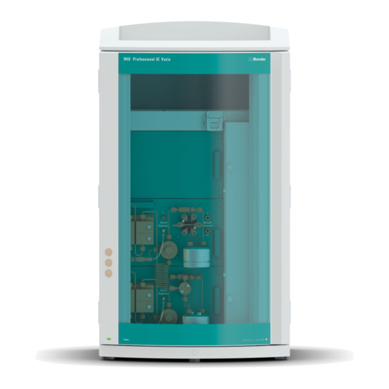
■■■■■■■■■■■■■■■■■■■■■■ 2 Overview of the instrument 2 Overview of the instrument Front Figure 1 Front Bottle holder Detector chamber Offers space for the eluent bottle(s) and Offers space for two embedded detectors additional accessories. and additional accessories. Column holder Column thermostat For a third separation column outside the With two column holders for two separation column thermostat. - Page 16 ■■■■■■■■■■■■■■■■■■■■■■ 2.1 Front Injection valve Pulsation absorber Inline filter 10 T connector 11 Pulsation absorber 12 Base tray With leak sensor. 13 Purge valve 14 Gradient pump B For deaerating the high-pressure pump. 15 Eluent degasser 16 Mixing coil 17 Purge valve 18 Gradient pump A For deaerating the high-pressure pump.
-
Page 17: Rear
■■■■■■■■■■■■■■■■■■■■■■ 2 Overview of the instrument Rear Figure 2 Rear Bottle holder Back panel Offers space for the eluent bottle(s) and Removable. Enables access to the detector additional accessories. chamber. Drainage tubing connection Transport locking screws For connecting the drainage tubing, which For securing the vacuum pump(s) when guides escaped liquids away from the detec- transporting the instrument. -
Page 18: Feed-Throughs For Capillaries And Cables
■■■■■■■■■■■■■■■■■■■■■■ 2.3 Feed-throughs for capillaries and cables Vacuum connection Exhaust opening For connecting an Extension Module that Labeled Exhaust. For extracting the air from has a degasser but not its own vacuum the vacuum chamber. pump. This connection has to be firmly sealed with a stopper when not in use. -
Page 19: Figure 3 Feed-Throughs On The Door
■■■■■■■■■■■■■■■■■■■■■■ 2 Overview of the instrument Openings on the door Figure 3 Feed-throughs on the door Luer connector Opening for capillaries For connecting a capillary from inside and For up to 3 capillaries. for inserting a syringe (6.2816.020) from outside. For manual sample injection. An opening for up to 3 capillaries is located on the door of the instru- ment. -
Page 20: Figure 4 Openings For Capillaries And Cables
■■■■■■■■■■■■■■■■■■■■■■ 2.3 Feed-throughs for capillaries and cables Openings on the back panel Figure 4 Openings for capillaries and cables Openings for capillaries Openings for cables The removable back panel is outfitted with openings through which capil- laries and cables can be lead out of the detector chamber. Ducts for capillaries There are ducts for capillaries between the instrument and base tray as well as between the instrument and the bottle holder. -
Page 21: Figure 5 Ducts For Capillaries
■■■■■■■■■■■■■■■■■■■■■■ 2 Overview of the instrument Figure 5 Ducts for capillaries ■■■■■■■■ 940 Professional IC Vario ONE/HPG (2.940.1140) -
Page 22: Installation
■■■■■■■■■■■■■■■■■■■■■■ 3.1 Setting up the instrument 3 Installation Setting up the instrument 3.1.1 Packaging The instrument is supplied in protective packaging together with the sepa- rately packed accessories. Keep this packaging, as only this ensures safe transportation of the instrument. 3.1.2 Checks Immediately after receipt, check whether the shipment has arrived com-... - Page 23 ■■■■■■■■■■■■■■■■■■■■■■ 3 Installation Also see: PEEK pressure screws 1x1 video on the Internet http://ic- help.metrohm.com. Connection capillaries PEEK capillaries and PTFE capillaries are used in the IC system. PEEK capillaries (poly- PEEK capillaries are pressure-stable up to 400 bar (depending on the inner etheretherketone) diameter), flexible, chemically inert and have an extremely smooth surface.
- Page 24 ■■■■■■■■■■■■■■■■■■■■■■ 3.2 Capillary connections in the IC system occurs if two capillary ends connected to each other do not fit exactly, thus allowing liquid to escape. There are two possible causes for this: The capillary ends do not have exactly flat edges. ■...
-
Page 25: Removing The Handle
■■■■■■■■■■■■■■■■■■■■■■ 3 Installation Removing the handle The instrument is equipped with a handle in order to make it easier to transport. The handle can be removed once the instrument is in place in the lab. Accessories You do not need any accessories for the following work steps. Removing the handle 1 Removing the handle Unscrew the four knurled screws. -
Page 26: Removing Transport Locking Screws
■■■■■■■■■■■■■■■■■■■■■■ 3.4 Removing transport locking screws Removing transport locking screws To avoid damage to the drives for the high-pressure pump and the vac- uum pump during transport, the pumps are secured with transport locking screws. These are located at the rear of the instrument and labeled with Transport security screws. -
Page 27: Connecting The Drainage Tubing And Leak Sensor
■■■■■■■■■■■■■■■■■■■■■■ 3 Installation Store the transport locking screws in a safe place. Reinsert the transport locking screws each time you transport the instrument a significant dis- tance. CAUTION The pumps may be damaged if you transport the instrument without inserting the transport locking screws. Connecting the drainage tubing and leak sensor The leak sensor detects leaking liquid that collects in the instrument's base tray. - Page 28 ■■■■■■■■■■■■■■■■■■■■■■ 3.5 Connecting the drainage tubing and leak sensor Connecting the drainage tubing 1 Cut a piece of silicone tubing into three pieces using scissors: 2 × approx. 40 cm and 1 × 20 cm. 2 Attach one end of the 40 cm long piece to the drainage tubing con- nection on the bottle holder.
-
Page 29: Connecting The Leak Sensor
■■■■■■■■■■■■■■■■■■■■■■ 3 Installation Route the loose end into a waste container. 3.5.2 Connecting the leak sensor Plugging in the leak sensor connection cable The leak sensor connection cable is coiled up in the base tray. 1 Pull the leak sensor connection cable out of the base tray as far as needed. -
Page 30: Connecting The Eluent Bottle
■■■■■■■■■■■■■■■■■■■■■■ 3.7 Connecting the eluent bottle Connecting the eluent bottle The eluent is aspirated out of the eluent bottle via the eluent aspiration tubing . The eluent aspiration tubing is installed on the entry to the eluent degasser. The tubing must be be fed out of the instrument through a suitable open- ing (see "Openings on the back panel", page 12) before the loose end can be connected to the eluent bottle. - Page 31 (6.2744.360), a syringe and the purge needle (6.2816.040). This procedure can also be found in the video "Inserting a new aspi- ration filter" at the following link: ic-help.metrohm.com 4 Mounting aspiration filter NOTE Always wear gloves when handling the aspiration filter.
-
Page 32: Figure 8 Installing Tubing Weighting And Aspiration Filter
■■■■■■■■■■■■■■■■■■■■■■ 3.7 Connecting the eluent bottle Figure 8 Installing tubing weighting and aspiration filter 5 Installing the eluent bottle cap on the eluent bottle Insert the eluent aspiration tubing into the eluent bottle ■ (6.1608.070). Tighten the bottle cap on the eluent bottle. ■... - Page 33 ■■■■■■■■■■■■■■■■■■■■■■ 3 Installation 6 Mounting the adsorber tube NOTE Depending on the eluent used, the adsorber tube (6.1609.000) must be filled differently: For alkaline eluents or eluents with a low buffer capacity: first a ■ little cotton, then with CO adsorber material.
-
Page 34: Connecting The Eluent Degasser
■■■■■■■■■■■■■■■■■■■■■■ 3.8 Connecting the eluent degasser Connecting the eluent degasser The high-pressure pump cannot generate uniform flow if the eluent con- tains small gas bubbles or dissolved gas. As a result, the baseline cannot be stabilized correctly. In order to achieve good measurement results, the eluent has to be degassed before it goes into the high-pressure pump. -
Page 35: Installing An Inline Filter
■■■■■■■■■■■■■■■■■■■■■■ 3 Installation 3.10 Installing an inline filter Inline filters protect the separation column reliably from potential contami- nation from the eluent. The small filter pads with 2 µm pore size can be replaced quickly and easily. They remove particles from the solutions. An inline filter (6.2821.120) is installed between the purge valve and the pulsation absorber as protection against particles. -
Page 36: Injection Valve
The quantity of sample solution injected is determined by: the volume of the sample loop or ■ by an 800 Dosino when the Metrohm intelligent Partial Loop Injection ■ Technique (MiPT), the Metrohm intelligent Pick-up Injection Technique (MiPuT) or the Metrohm Inline Preconcentration (MiPCT, MiPCT-ME) is used. -
Page 37: Figure 12 Exchanging The Sample Loop
■■■■■■■■■■■■■■■■■■■■■■ 3 Installation Application Sample loop MiPCT, MiPCT-ME Preconcentration column The injection valve is completely connected. No installation work is required. Optional: Exchanging the sample loop The sample loop can be replaced to match the application (see Table 1, page 28). NOTE Only use PEEK pressure screws (6.2744.010) to connect capillaries and the sample loop to the injection valve. -
Page 38: Installing The Conductivity Detector
■■■■■■■■■■■■■■■■■■■■■■ 3.13 Installing the conductivity detector Exchanging the sample loop NOTE Observe a dead-volume-free installation of the sample loop (see "Creat- ing dead-volume-free capillary connections", page 16). 1 Removing the existing sample loop Loosen the pressure screws (6.2744.010) at Port 3 and Port 6. ■... -
Page 39: Installing The Amperometric Detector
■■■■■■■■■■■■■■■■■■■■■■ 3 Installation 1 Connect the column inlet capillary and the detector inlet capillary to one another using a coupling (6.2744.040) and two short pressure screws (6.2744.070). 3.14 Installing the amperometric detector The 940 Professional IC Vario provides enough space for two detectors and additional accessories in the detector chamber. - Page 40 ■■■■■■■■■■■■■■■■■■■■■■ 3.15 Connecting the sample degasser (optional) Connecting the sample degasser CAUTION If the sample degasser is not used, the inlet and outlet must be sealed with threaded stoppers (6.2744.220). 1 Removing the threaded stoppers Remove and keep the threaded stoppers (6.2744.220) from the inlet and outlet of the sample degasser.
-
Page 41: Installing The High-Pressure Gradient Module
■■■■■■■■■■■■■■■■■■■■■■ 3 Installation Guide the other end of the PTFE capillary (6.1803.040) out of the ■ instrument through a capillary feed-through and connect it to the Sample Processor, if applicable. Try to ensure the shortest possible connections (shorten the capil- lary if necessary). -
Page 42: Connecting The Instrument To The Power Grid
Unplug the power plug immediately if you suspect that moisture has ■ gotten inside the instrument. Only personnel who have been issued Metrohm qualification may ■ perform service and repair work on electrical and electronic parts. ■■■■■■■■... -
Page 43: Initial Start-Up
■■■■■■■■■■■■■■■■■■■■■■ 3 Installation Connecting the power cord Accessories Power cord, three-core with IEC 60320 instrument plug type C13. Con- ductor cross-section 1 mm / 18 AWG. Power plug according to customer requirement (6.2122.XX0). Do not use a not permitted power cord. 1 Plugging in the power cord Plug the power cord into the instrument's power socket. - Page 44 ■■■■■■■■■■■■■■■■■■■■■■ 3.19 Initial start-up MagIC Net detects the instrument and all of its modules. 3 Starting equilibration Start the equilibration in MagIC Net: Workplace ▶ Run ▶ Equili- ■ bration ▶ Start HW. 4 Deaerating the high-pressure pump Push the end of the purge needle (6.2816.040) over the end of ■...
-
Page 45: Connecting And Rinsing The Guard Column
Connecting and rinsing the guard column Guard columns protect separation columns and significantly increase their service life. The guard columns available from Metrohm are either actual guard columns or guard column cartridges used together with a cartridge holder. The process of installing a guard column cartridge into the corre- sponding holder is described in the guard column leaflet. - Page 46 ■■■■■■■■■■■■■■■■■■■■■■ 3.20 Connecting and rinsing the guard column NOTE The guard column may not be connected until after the instrument has already been put into operation once (see Chapter 3.19, page 35). The guard column and the separation column have to be replaced by a cou- pling (6.2744.040) until then.
-
Page 47: Connecting The Separation Column
NOTE Information regarding which separation column is suitable for your application can be found in the Metrohm Column Program, the product information for the separation column or it can be obtained through your representative. - Page 48 ■■■■■■■■■■■■■■■■■■■■■■ 3.21 Connecting the separation column CAUTION New separation columns are filled with a solution and sealed with stop- pers on both sides. Before inserting the column, ensure that this solu- tion can be mixed with the eluent being used (follow the information provided by the manufacturer).
- Page 49 ■■■■■■■■■■■■■■■■■■■■■■ 3 Installation Connecting the separation column 1 Removing the stoppers Remove the stoppers from the separation column. ■ ■■■■■■■■ 940 Professional IC Vario ONE/HPG (2.940.1140)
- Page 50 ■■■■■■■■■■■■■■■■■■■■■■ 3.21 Connecting the separation column 2 Installing the inlet of the separation column CAUTION When inserting the column, ensure that it is inserted correctly based on the marked flow direction. There are three options: Attach the column inlet directly onto the guard column or, ■...
-
Page 51: Conditioning
■■■■■■■■■■■■■■■■■■■■■■ 3 Installation 3.22 Conditioning In the following cases, the system must be conditioned with eluent until a stable baseline has been reached: After installation ■ After each time the instrument is switched on ■ After each eluent change ■ NOTE The conditioning time can lengthen considerably if the composition of the eluent is modified. - Page 52 ■■■■■■■■■■■■■■■■■■■■■■ 3.22 Conditioning Visually inspect whether all capillaries and their connections from ■ the high-pressure pump to the detector are leak-tight. If eluent is leaking out anywhere, tighten the corresponding pressure screw further, or loosen the pressure screw, check the end of the capil- lary and shorten it using the capillary cutter if necessary and retighten the pressure screw.
-
Page 53: Operation
■■■■■■■■■■■■■■■■■■■■■■ 4 Operation 4 Operation The 940 Professional IC Vario ONE/HPG is operated solely using the MagIC Net software. You can find information on operating the software in the tutorial for MagIC Net or in the online help. ■■■■■■■■ 940 Professional IC Vario ONE/HPG (2.940.1140) -
Page 54: Operation And Maintenance
Maintenance by Metrohm Service Maintenance of the instrument is best carried out as part of an annual service performed by specialist personnel from Metrohm. A shorter main- tenance interval is recommended if you frequently work with caustic and corrosive chemicals. Metrohm Service offers every form of technical advice for maintenance and service of all Metrohm instruments. -
Page 55: Shutting Down And Recommissioning
3 Rinse the IC system for 15 minutes with methanol/ultrapure water mixture (1:4). 4 Optional: Only if the IC system is equipped with a suppressor. In the software, switch the Metrohm Suppressor Module (MSM) twice during the rinsing process at five-minute intervals in each case (STEP command). -
Page 56: Capillary Connections
■■■■■■■■■■■■■■■■■■■■■■ 5.2 Capillary connections Capillary connections All capillary connections between the injection valve, the separation col- umn and the detector must be as short as possible, have a low dead vol- ume and be completely leak-tight. The PEEK capillary downstream of the detector must be free of blockages. Use only PEEK capillaries with an inner diameter of 0.25 mm between the high-pressure pump and the detector (high-pressure section). -
Page 57: Figure 13 Column Thermostat
■■■■■■■■■■■■■■■■■■■■■■ 5 Operation and maintenance Figure 13 Column thermostat Openings Preheating grooves For feeding capillaries into and out of the For regulating the temperature of the eluent. instrument. Column holder With column recognition. For fastening the column. ■■■■■■■■ 940 Professional IC Vario ONE/HPG (2.940.1140) -
Page 58: Handling The Eluent
■■■■■■■■■■■■■■■■■■■■■■ 5.5 Handling the eluent Replacing the preheating capillaries In order to make threading the column inlet capillary into the column ther- mostat's preheating grooves easier, we recommend loosening the screws for the holder plate a little, but not removing them all the way. 1 Guide the column inlet capillary into the column thermostat via a suitable opening (13-1). -
Page 59: Changing The Eluent
■■■■■■■■■■■■■■■■■■■■■■ 5 Operation and maintenance The composition of the eluent plays a critical role in chromatographic analysis: Concentration An increase in the concentration generally leads to shorter retention times and faster separation, but also to a higher background conductivity sig- nal. -
Page 60: Notes On Operating The High-Pressure Pump
■■■■■■■■■■■■■■■■■■■■■■ 5.7 Notes on operating the high-pressure pump Connecting the connecting tubing Insert the clamping screws on the connector and screw them in ■ by hand. Tighten the clamping screws with the wrench. ■ Notes on operating the high-pressure pump CAUTION The pump head is filled ex works with methanol/ultrapure water. -
Page 61: Servicing The High-Pressure Pump
5 Operation and maintenance Servicing the high-pressure pump NOTE You can find a video sequence for this task in the Multimedia Guide IC Maintenance or on the Internet at http://ic-help.metrohm.com/. Figure 14 High-pressure pump – Parts Pressure screw, short (6.2744.070) Outlet valve holder Fastened to the outlet valve holder. - Page 62 Insert the piston. Reinstall the pump head. You can find brief video sequences on the following maintenance steps on the Internet at http://ic-help.metrohm.com/. Servicing the outlet valve and inlet valve Accessories For this step, you need the following accessories: You can find these parts in the accessory kit: Vario/Flex Basic (6.5000.000).
- Page 63 ■■■■■■■■■■■■■■■■■■■■■■ 5 Operation and maintenance Cleaning the outlet valve Spare parts If the outlet valve cannot be cleaned, you will need a new outlet valve (6.2824.160) for this step. 1 Removing the outlet valve Unscrew the connection capillary to the auxiliary piston from the ■...
- Page 64 ■■■■■■■■■■■■■■■■■■■■■■ 5.8 Servicing the high-pressure pump 3 Reinserting the outlet valve into the pump head Insert the outlet valve into the outlet valve holder (the seal must ■ be visible) (1). Screw the outlet valve holder up into the pump head (2) and ■...
- Page 65 ■■■■■■■■■■■■■■■■■■■■■■ 5 Operation and maintenance Cleaning the inlet valve Spare parts If the inlet valve cannot be cleaned, you will need a new inlet valve (6.2824.170) for this step. 1 Removing the inlet valve Unscrew the connection capillary to the connection of the eluent ■...
- Page 66 ■■■■■■■■■■■■■■■■■■■■■■ 5.8 Servicing the high-pressure pump 3 Reinserting the inlet valve into the pump head Insert the inlet valve into the inlet valve holder (the seal must be ■ visible) (1). Screw the inlet valve holder up into the pump head (2) and ■...
- Page 67 ■■■■■■■■■■■■■■■■■■■■■■ 5 Operation and maintenance 1 Release the coupling from the pressure screw and seal it with a stop- per. 2 Unscrew and remove the pressure screw on the pump head's outlet (14-8). 3 Loosen and remove the four fastening screws (14-3) using the hex key.
-
Page 68: Figure 15 High-Pressure Pump - Cross-Section
■■■■■■■■■■■■■■■■■■■■■■ 5.8 Servicing the high-pressure pump Figure 15 High-pressure pump – Cross-section Outlet valve holder Outlet valve (6.2824.160) Backup ring Piston seal (6.2741.020) Pump head Inlet valve (6.2824.170) Inlet valve holder Zirconium oxide piston (6.2824.070) Piston cartridge Accessories For this step, you need the following accessories: You can find these parts in the accessory kit: Vario/Flex Basic (6.5000.000). -
Page 69: Figure 16 Tool For Piston Seal (6.2617.010)
■■■■■■■■■■■■■■■■■■■■■■ 5 Operation and maintenance Figure 16 Tool for piston seal (6.2617.010) Sleeve Spare part For this step, you need a new piston seal (6.2741.020). Replacing the piston seal Figure 17 Removing the piston cartridge from the pump head Piston cartridge Backup ring 1 Removing the piston cartridge Loosen the piston cartridge (17-1) using the adjustable wrench and... -
Page 70: Figure 18 Inserting The Piston Seal Into The Tool
■■■■■■■■■■■■■■■■■■■■■■ 5.8 Servicing the high-pressure pump 3 Removing the old piston seal CAUTION Screwing the (6.2617.010) special tool for the piston seal into the piston seal destroys this completely! CAUTION Avoid touching the sealing surface in the pump head with the tool! Only screw the tip (16-1) of the tool for the piston seal far enough into the piston seal that the seal can be pulled out. -
Page 71: Figure 19 Parts Of The Piston Cartridge
■■■■■■■■■■■■■■■■■■■■■■ 5 Operation and maintenance The pump head has been removed (see "Removing the pump head", ■ page 58). The piston cartridge is removed (see "Replacing the piston seal", page ■ 61). For this task, you need the following accessories: Zirconium oxide piston (6.2824.070) ■... - Page 72 ■■■■■■■■■■■■■■■■■■■■■■ 5.8 Servicing the high-pressure pump 2 Cleaning the parts of the piston cartridge If the zirconium oxide piston has become contaminated due to ■ abrasion or deposits, then clean it using a fine abrasive cleaning powder, rinse it using ultrapure water until it is free of particles and dry it.
- Page 73 ■■■■■■■■■■■■■■■■■■■■■■ 5 Operation and maintenance 4 mm hex key (6.2621.030) ■ Mounting the pump head NOTE The pump head cannot be mounted the wrong way, as it has fastening bolts with different bore hole depths, i.e., one fastening bolt is longer than all others.
-
Page 74: Servicing The Inline Filter
Servicing the inline filter NOTE You can find a video sequence for this task in the Multimedia Guide IC Maintenance or on the Internet at http://ic-help.metrohm.com/. Maintenance interval The filter must be replaced at least every 3 months; it may need to be replaced more frequently, depending on the application. -
Page 75: Figure 20 Inline Filter - Removing The Filter
■■■■■■■■■■■■■■■■■■■■■■ 5 Operation and maintenance Removing the filter Figure 20 Inline filter – Removing the filter Filter housing Filter screw Inline filter housing. Part of the accessories Screw for the inline filter. Part of the acces- (6.2821.120). sories (6.2821.120). Filter (6.2821.130) Pack contains 10 pieces. - Page 76 ■■■■■■■■■■■■■■■■■■■■■■ 5.9 Servicing the inline filter Inserting a new filter 1 Inserting a new filter Use tweezers to carefully place a new filter into the filter screw ■ (20-2) so that it is flat and press it firmly into place with the rear of the tweezers.
-
Page 77: Servicing The Pulsation Absorber
The pulsation absorber is maintenance-free and must not be opened. 5.11 Injection valve Maintenance on the injection valve is best performed by specialist person- nel from Metrohm during annual service. 5.12 Servicing the detector Follow the maintenance instructions in the the detector's manual. - Page 78 ■■■■■■■■■■■■■■■■■■■■■■ 5.13 Rinsing the sample path 2 Unscrewing the sample loop Unscrew the end of the sample loop. 3 Aspirating the sample and measuring the time Aspirate a sample typical for the later application and use a stop- watch to measure the time the sample needs to go from the sample vessel to the end of the sample loop.
-
Page 79: Separation Column
You can find detailed information on the separation columns available from Metrohm in the leaflet provided along with your separation column, in the Metrohm IC Column Program (available from your Metrohm representative) or on the Internet at http://www.metrohm.com... -
Page 80: Quality Management And Qualification With Metrohm
Metrohm offers you comprehensive support in implementing quality man- agement measures for instruments and software. Qualification Please contact your local Metrohm representative for support in qualifica- tion of instruments and software. The Installation Qualification (IQ) and Operational Qualification (OQ) are offered by Metrohm represen- tatives as a service. -
Page 81: Troubleshooting
■■■■■■■■■■■■■■■■■■■■■■ 6 Troubleshooting 6 Troubleshooting Problem Cause Remedy Marked drop in Leak in the system. Check the capillary connections and seal leaks, pressure. if necessary (see Chapter 3.2, page 14). The baseline has a The eluent is not suffi- Ensure that the connectors for the eluent large amount of ciently degassed. - Page 82 Replace the separation column (see "Con- ■ necting the separation column", page 41). Note: Samples should always be microfiltered . Injection valve – blocked. Have the valve cleaned (by a Metrohm service engineer). The retention times Eluent - Incorrect concen- Create eluent with correct concentration.
- Page 83 ■■■■■■■■■■■■■■■■■■■■■■ 6 Troubleshooting Problem Cause Remedy Individual peaks are Sample – Sample carry- Check the rinsing time (see "Checking the rins- greater than expec- over from previous meas- ing time", page 70). ted. urements. The background The incorrect eluent is Change the eluent (see Chapter 5.5.2, page conductivity is too being used.
- Page 84 ■■■■■■■■■■■■■■■■■■■■■■ Problem Cause Remedy Injection valve – Defective. Request Metrohm Service. Vacuum is not being Eluent degasser – Vacuum Seal the Vacuum connector tightly with a ■ built connection on the rear of threaded stopper (6.1446.040). the instrument is not (tightly) sealed.
-
Page 85: Technical Specifications
■■■■■■■■■■■■■■■■■■■■■■ 7 Technical specifications 7 Technical specifications Reference conditions The technical specifications listed in this chapter refer to the following ref- erence conditions: Ambient tempera- +25 °C (± 3 °C) ture Instrument status Operating > 40 minutes (in equilibrium) Instrument IC system Metal-free IC system ■... -
Page 86: Housing
■■■■■■■■■■■■■■■■■■■■■■ 7.4 Housing Housing Dimensions Width 365 mm Height 642 mm Depth 380 mm Controls LED standby indicator Indicators On/off switch On the rear of the instrument Weight 2.940.1140 36.43 kg (without accessories) Leak sensor Type Electronic, no calibration necessary Column thermostat Type Thermostat using Peltier technology for two intelligent separation col-... -
Page 87: Eluent Degasser
■■■■■■■■■■■■■■■■■■■■■■ 7 Technical specifications Eluent degasser Material Fluoropolymer Resistance to sol- No restriction (except PFC) vents Time to establish < 60 s vacuum High-pressure pump Type Serial dual-piston pump ■ Intelligent pump head recognition ■ Chemically inert ■ Metal-free pump heads ■... -
Page 88: Injection Valve
■■■■■■■■■■■■■■■■■■■■■■ 7.10 Injection valve Gradient capabil- Isocratic or gradient (extendable to quaternary) Profile Step, linear, convex and concave Resolution < 1 nL/min 7.10 Injection valve Actuator switch- typ. 100 ms ing time Maximum operat- 35 MPa (350 bar) ing pressure Material PEEK 7.11... -
Page 89: Interfaces
■■■■■■■■■■■■■■■■■■■■■■ 7 Technical specifications 7.14 Interfaces Input 1 USB upstream, type B (labeled PC for connecting to a computer) Output 2 USB downstream, type A (labeled USB 1 and USB 2) 2 MSB 8-pin Mini DIN (female) (labeled MSB 1 and MSB 2 for Dosino, stirrer, remote lines, etc.) 2 15-pin high-density D-sub (female) (labeled Detector 1 and Detec- Detector... -
Page 90: Accessories
Internet. You can download this information using the article number as follows: Downloading the accessories list 1 Type https://www.metrohm.com/ into your Internet browser. 2 Under Find products, accessories, and applications by, enter the article number (e.g. 2.940.1140). -
Page 91: Index
■■■■■■■■■■■■■■■■■■■■■■ Index Index Technical specifications ..80 Ambient conditions ....77 Electrostatic charge ....4 Inline filter ........ 27 Aspiration filter (6.2821.090) ..50 Eluent Installation Aspiration tubing for eluent ..22 Aspirate ......22 Column thermostat .... 21 Change ......51 Connections ....... - Page 92 ■■■■■■■■■■■■■■■■■■■■■■ Index Precipitate ........ 52 Sample loop ....... 28 Injection valve ....80 Pressure increase ...... 52 Transfer time ...... 69 Interfaces ......81 Pressure limit ......79 Sample degasser Leak sensor ......78 Pressure range ......79 Installation ......31 Reference conditions ..
Need help?
Do you have a question about the 940 Professional IC Vario HPG and is the answer not in the manual?
Questions and answers