Table of Contents
Advertisement
Quick Links
Advertisement
Table of Contents

Related Manuals for Metrohm NIRS XDS


Summary of Contents for Metrohm NIRS XDS
- Page 1 NIRS XDS Process Analyzer Hardware & Installation Manual 8.928.8001EN...
- Page 3 Metrohm Applikon B.V. Schiedam The Netherlands Phone +31 (0)10-2983555 Fax +31 (0)10-4379648 analyzers@metrohm-applikon.com www.metrohm-applikon.com NIRS XDS Process Analyzer Hardware & Installation Manual 8.928.8001EN November 2016 JZa...
- Page 4 © 2017, Metrohm Applikon B.V. All rights reserved. This manual is protected by copyright law. Without the prior written approval of Metrohm Applikon B.V., this manual and any contents thereof may not be reproduced, stored or made public in any form by any means.
-
Page 5: Table Of Contents
4.3.3 Purged System for Hazardous Environments ......27 Instrument with Accessories ..........28 4.4.1 Single Point ................28 4.4.2 Multiplexer ................29 5 Technical specifications Basic Unit with Heat sink and Fans dimensions ....31 ■■■■■■■■ NIRS XDS Process Analyzer... - Page 6 Installation ................49 Configuring ................ 51 7.2.1 Setting up the network properties in Windows ...... 51 7.2.2 Establishing the communication between Vision and your XDS Process Analyzer ............. 54 7.2.3 Parameters in Configure, Options ........... 61 ■■■■■■■■ NIRS XDS Process Analyzer...
- Page 7 Instrument Calibration, Transmission Probes ......98 7.5.4 Window Correction, Transmission Probes ......100 7.5.5 Performance Test, Transmission Probes ......... 104 8 Maintenance of the Instrument Lamp Replacement ............106 Fuse Replacement ............113 9 Troubleshooting ■■■■■■■■ NIRS XDS Process Analyzer...
-
Page 9: General
12 months from the day of commissioning or 18 months from delivery, whichever comes first. The warranty remains valid on condition that the service is provided by an authorized Metrohm Applikon service organization. The warranty for the accuracy corresponds to the technical specifications given in this manual. -
Page 10: Safety Instructions
All relevant safety measures are to be observed when working with equip- ment. WARNING Only personnel qualified by Metrohm Applikon are authorized to carry out service work on the analyzer. WARNING Only connect the analyzer to other equipment that is in compliance with the appropriate directives (i.e.: LVD, EMC etc.). -
Page 11: Potentially Hazardous Solvents And Chemicals
The correct disposal of your old equipment will help to prevent negative effects on the environment and public health. More details about the disposal of your old equipment can be obtained from your local authorities, from waste disposal companies or from your local dealer. ■■■■■■■■ NIRS XDS Process Analyzer... -
Page 12: List Of Abbreviations
L/min Liter per minute Pounds Light Emitting Diodes Low Voltage Directive millimeter Near InfraRed National Pipe Thread Tapered Thread Outer diameter Pounds per square inch SubMiniature version A Universal Serial Bus Voltage in Alternating Current ■■■■■■■■ NIRS XDS Process Analyzer... -
Page 13: Introduction
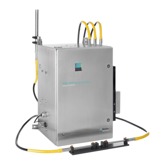
■■■■■■■■■■■■■■■■■■■■■■ 2 Introduction 2 Introduction Congratulations on your purchase of an NIRS XDS Process Analyzer from Metrohm Process Analytics! We welcome you to our family of satisfied customers who enjoy the benefits of the highest quality NIR. The NIRS XDS Process Analyzer provides the next generation of process analyzers for real-time analysis in the pharmaceutical, chemical and petro- chemical industries. - Page 14 (microbundle) for the reflectance probe. Note the main components of the instrument from the light source to the detector: the lamp box, the optical fibers, the probes, the Multiplexer, the monobox and the detector. ■■■■■■■■ NIRS XDS Process Analyzer...
- Page 15 ■■■■■■■■■■■■■■■■■■■■■■ 2 Introduction Figure 1 System overview Figure 2 System corresponding to the schematic system overview ■■■■■■■■ NIRS XDS Process Analyzer...
-
Page 16: Overview Of The Instrument
(operating or not) and whether enclosure. This is normally set to 38.0 °C the instrument is scanning or not. Mounting brackets The mounting brackets are used to install and suspend the analyzer. ■■■■■■■■ NIRS XDS Process Analyzer... -
Page 17: Left Side View Of The Analyzer
Wiring must follow all local codes and requirements. Plugs The four plugs shown are for the optional purge unit. On the Basic XDS Process Ana- lyzer, these plugs remain in place as shown. ■■■■■■■■ NIRS XDS Process Analyzer... - Page 18 (IP66) fittings for enclosure flow are used. Protective gas supply inlet The protective gas supply to the enclosure system must be a clean, instrument quality compressed air or inert gas filtered to a mini- mum of 40 microns. ■■■■■■■■ NIRS XDS Process Analyzer...
-
Page 19: Right Side View Of The Analyzer
Heat sinks are used as a mean to air-cool the Two fans allow air circulation through the process analyzer (Operating temperature heat sink for controlling the temperature of range: 0 - 30 °C) the process analyzer enclosure. ■■■■■■■■ NIRS XDS Process Analyzer... - Page 20 The compressed air supply must be filtered to remove water and dirt using a 5 micron or smaller filter. Failure to use a filter may cause clogging (and freezing) of the com- pressed air paths inside the system. ■■■■■■■■ NIRS XDS Process Analyzer...
- Page 21 ■■■■■■■■■■■■■■■■■■■■■■ 3 Overview of the instrument 3.1.3.3 Right side view with AC cooling AC cooling AC cooling is used to operate the instrument in an environment between 0 and 50 °C ■■■■■■■■ NIRS XDS Process Analyzer...
-
Page 22: Top View Of The Analyzer
Basic XDS Process Analyzer, the plug remains fibers. For channels which are not used, the in place as shown. plugs remain in place. Optical fiber Connection A microbundle fiber is tightly connected to the XDS process Analyzer. ■■■■■■■■ NIRS XDS Process Analyzer... -
Page 23: Interior View Of The Analyzer
For process analyzer equipped with a purge on wire rope shock absorbers to minimize unit, an optical fiber modem is provided. In the effect of vibration in the ambient envi- the basic configuration the space remains ronment. empty. ■■■■■■■■ NIRS XDS Process Analyzer... - Page 24 A manual key is provided for the interlock to each channel. Note that for single point switch, for use during initial set-up. This key process analyzers the upper part is not is red, and is shaped like the letter “I”. present. ■■■■■■■■ NIRS XDS Process Analyzer...
-
Page 25: Overview Of The Accessories
They are used when single fibers fail to bring enough light to the sample. They are composed of 40 individual fiber bun- dled together (see picture). They are always used as a pair. ■■■■■■■■ NIRS XDS Process Analyzer... -
Page 26: Fibres Connectors
The dark spot at the center of the SMA connector is the fibre of each type. Because the micro-bundle has more fibres, it has a greater light-car- rying capacity. It is therefore possible to measure denser samples. ■■■■■■■■ NIRS XDS Process Analyzer... -
Page 27: Probes
This photo shows threaded transmission probes, which come with several spacers (2 mm shown) which maintain the probes at a pre-determined dis- tance for consistent analysis. ■■■■■■■■ NIRS XDS Process Analyzer... -
Page 28: Probe Disassembly
It may be necessary to remove the outer lens barrel from the fiber optic bundle for mounting. Follow these instructions. (Instructions apply only to the probe type shown.) 1 Note the knurled collar. To remove the lens barrel, unscrew the knurled collar. ■■■■■■■■ NIRS XDS Process Analyzer... - Page 29 The knurled collar is captured, and will not fall off. Do not use the set screws – the knurled collar sets the gap, and the set screws will inter- fere with that setting. 4 To re-assemble, gently insert the fiber optic bundle end into the lens barrel. ■■■■■■■■ NIRS XDS Process Analyzer...
- Page 30 On high temperature vacuum vessels, this technique minimi- zes pressure stress on the probe window. If used, remove the 1/16”set screw using a 3/32” Allen wrench. Use a suitable 1/16” NPT fitting to connect. ■■■■■■■■ NIRS XDS Process Analyzer...
- Page 31 Window gapping may be an issue with retrofits. Consult factory for proper procedure. 2 After tightening the set screws, move the snap ring into the groove to retain the knurled knob. This protects the set screws from dirt and tampering. ■■■■■■■■ NIRS XDS Process Analyzer...
-
Page 32: Probe Drawings
DO NOT USE THESE DRAWINGS without verifying current dimensions, fittings and materials with Metrohm Applikon B.V.. Metrohm Applikon B.V. is not responsible for use of these drawings for probe installation. Always request current probe drawings before finalizing installation. - Page 33 ■■■■■■■■■■■■■■■■■■■■■■ 4 Overview of the accessories Figure 4 Typical Interactance Immersion Probe Style Figure 5 Typical Transmission Probe Style with threaded spacer ■■■■■■■■ NIRS XDS Process Analyzer...
-
Page 34: Xds Process Options
Whether the length of the Ethernet cable should exceed 75 m, it is recom- mended to use fiber optic. Communication cable should be handled carefully to avoid breakage. Avoid sharp bends, chafing, or other damage. ■■■■■■■■ NIRS XDS Process Analyzer... -
Page 35: Purged System For Hazardous Environments
4 Overview of the accessories 4.3.3 Purged System for Hazardous Environments Metrohm Process Analytics offers the option of a purging system for haz- ardous environment use. The compact purging system is designed to meet European approvals as well as North American standards. -
Page 36: Instrument With Accessories
Figure 6 XDS Process Analyzer, single point, single fibers Figure 7 XDS Process Analyzer, single point microbundle, reflectance probe ■■■■■■■■ NIRS XDS Process Analyzer... -
Page 37: Multiplexer
Note that for this latest configuration a microbundle multiplexed instrument has to be considered. Consult with Metrohm Applikon specialists for more information. Figure 9 XDS Process Analyzer, multiplexer microbundle, reflectance probe + transmission pair ■■■■■■■■... - Page 38 ■■■■■■■■■■■■■■■■■■■■■■ 4.4 Instrument with Accessories Figure 10 XDS Process Analyzer, multiplexer microbundle, reflectance probe + transmission pair & single fiber transmission pair ■■■■■■■■ NIRS XDS Process Analyzer...
-
Page 39: Technical Specifications
■■■■■■■■■■■■■■■■■■■■■■ 5 Technical specifications 5 Technical specifications Basic Unit with Heat sink and Fans dimensions Dimensions Width 485 mm (19.09”) Height 646 mm (25.43”) Depth 358 mm (14.09”) ■■■■■■■■ NIRS XDS Process Analyzer... -
Page 40: Basic Unit With Vortex Cooling Dimensions
■■■■■■■■■■■■■■■■■■■■■■ 5.2 Basic Unit with Vortex Cooling dimensions Basic Unit with Vortex Cooling dimensions Dimensions Width 619 mm (24.37”) Height 646 mm (25.43”) Depth 358 mm (14.09”) ■■■■■■■■ NIRS XDS Process Analyzer... -
Page 41: Basic Unit With Air Conditioning Dimensions
■■■■■■■■■■■■■■■■■■■■■■ 5 Technical specifications Basic Unit with Air Conditioning dimensions Dimensions Width 513 mm (20.19”) Height 646 mm (25.43”) Depth 358 mm (14.09”) ■■■■■■■■ NIRS XDS Process Analyzer... -
Page 42: Purged Unit With Vortex Cooling
■■■■■■■■■■■■■■■■■■■■■■ 5.4 Purged Unit with Vortex cooling Purged Unit with Vortex cooling Width 879 mm (34.60”) Height 702 mm (27.64”) Depth 358 mm (14.09”) ■■■■■■■■ NIRS XDS Process Analyzer... -
Page 43: Purged Unit With Ac Cooling
Weight (kg) Weight (lbs) Basic System 41.9 92.3 With Vortex Cooler 48.0 105.8 With Purge Control and Vortex 59.4 130.9 Cooler With Air Conditioning 50.5 111.3 With Purge Control and Air Condi- 61.9 136.4 tioning ■■■■■■■■ NIRS XDS Process Analyzer... -
Page 44: Operating Temperature Range
10-90 % non-condensing Mains connection Voltage 100/240 VAC Selectable Frequency 50/60 Hz Amperage 2 A / 1.5 A Amperage with Air Conditioning 5 A / 2.7 A (optional) Power consumption (non Air Con- 100 W ditioning) ■■■■■■■■ NIRS XDS Process Analyzer... -
Page 45: Air Consumption
NIR energy output and assure stable illumination. A spare lamp is provided in the Accessory Kit. Do not substitute any lamp other than that available from Metrohm Process Analytics or its authorized distributor. Metrohm Process Analytics is not responsible for damage, lost production time, or warranty claims arising from unauthorized use of a non- Metrohm Process Analytics lamp. -
Page 46: Communication
■■■■■■■■■■■■■■■■■■■■■■ 5.15 Communication 5.15 Communication UTP Crossover Cable, Category 5, RJ-45 connection 5.16 Process communication Process communication can be done using the following protocols: Digital protocols : MODBUS, PROFIBUS, OPC I/O module: 4-20 mA ■■■■■■■■ NIRS XDS Process Analyzer... -
Page 47: Installation
Always wear safety glasses, safety shoes and other protective equipment as required. Leave adequate mounting space for all installed options, as well as room for air circulation and wiring access. Recommended minimum access and mounting space is as describes ■■■■■■■■ NIRS XDS Process Analyzer... - Page 48 153 mm (6”). Diameter should be at least 305 mm (12”). 2 Install a large washer, locking washer and nut onto each of the two upper mounting studs. Tighten nuts to the torque recommended by the fastener supplier. ■■■■■■■■ NIRS XDS Process Analyzer...
-
Page 49: Removal Of Shipping Restraints
Release the shipping restraints as shown. The shipping restraints are three (3) captive screws, circled in green on the photo. Two are on the top of the monochromator box, and one is at the bottom. ■■■■■■■■ NIRS XDS Process Analyzer... - Page 50 The shipping restraints should be locked down any time the instrument is moved, to prevent damage. Follow the reverse of the above procedure to lock the monochromator down for shipment. ■■■■■■■■ NIRS XDS Process Analyzer...
-
Page 51: Fiber Optics
The fiber may be installed in a “ladder tray” with supports every 100-150 mm (4-6 inches). Note the minimum fiber bend radius mentioned above. ■■■■■■■■ NIRS XDS Process Analyzer... -
Page 52: Multiplexer
AC Power (Mains) connection is done at the terminal strip inside the XDS Process Analyzer enclosure, as shown in the photo below: ■■■■■■■■ NIRS XDS Process Analyzer... -
Page 53: Ac Power Switch Settings
There are two switches that must be set for the supplied operating volt- age. These are: Heater switch The first switch (Heater) is at the center of the circle in the above diagram. Switch position is as follows: ■■■■■■■■ NIRS XDS Process Analyzer... -
Page 54: Network Connection
Because this switch is rather inaccessible, it is factory-set for the voltage in the destination location. If this switch needs to be reset due to instrument relocation, please advise Metrohm Applikon of this fact. Instructions will be supplied for changing the voltage. -
Page 55: Purged Unit Instrument Rj-45 Connection
The fibers must be fed into the enclosure using a proper fitting, as shown. The RJ-45 ports are auto-sensing for 10Base-T, 100Base-TX or 1000Base-T devices connections. Auto MDI/MDIX means that you can connect to another switch or workstation without changing the crossover cabling. ■■■■■■■■ NIRS XDS Process Analyzer... -
Page 56: Temperature Controller Set-Up
38.0 °C, equal to the set point. This indicates a stable temper- ature situation. The upper number (red LED) indicates actual enclosure temperature. The lower number (green LED) indicates the set-point value. Normal tempera- ture operation is comprised between 37 and 39 °C. ■■■■■■■■ NIRS XDS Process Analyzer... -
Page 57: Vision Software Operation
1 Install Vision on the computer to be used for instrument operations. Launch the .exe file from vision CD-ROM or USB stick. A first window appears, click on Next. 2 Enter your user name, your organization and type in the provided serial number. Click on Next. ■■■■■■■■ NIRS XDS Process Analyzer... - Page 58 Click on Next. 4 Choose a destination folder for Vision software. It is recommended to use the default location. (C:\Vision). Click on Next. 5 In the new window, click on Install. You must have admin rights. ■■■■■■■■ NIRS XDS Process Analyzer...
-
Page 59: Configuring
VPNs as well as your wireless adapter are disabled. 1 Right click on the icon of your connection in the task bar of Win- dows. Click on Open network and Sharing Center ■■■■■■■■ NIRS XDS Process Analyzer... - Page 60 ■■■■■■■■■■■■■■■■■■■■■■ 7.2 Configuring 2 In the left column, click on Change adapter settings 3 Double click on Local Area Connection ■■■■■■■■ NIRS XDS Process Analyzer...
- Page 61 ■■■■■■■■■■■■■■■■■■■■■■ 7 Vision Software Operation 4 A new window pops up. Click on Properties. 5 Double click on Internet Protocol Version 4 (TCP/IPv4) ■■■■■■■■ NIRS XDS Process Analyzer...
-
Page 62: Establishing The Communication Between Vision And Your Xds Process Analyzer
Obtain DNS server address automatically. Click on OK. Your instrument should be now detectable by the software. 7.2.2 Establishing the communication between Vision and your XDS Process Analyzer 1 The log-in box appears on the opening screen. ■■■■■■■■ NIRS XDS Process Analyzer... - Page 63 Assign to the project some meaningful name, to make it easy to remember. For our purposes, we simply called this “projectx”. Please use a more descriptive name. (no space allowed) Vision will assign a Location; leave this blank. ■■■■■■■■ NIRS XDS Process Analyzer...
- Page 64 If no IP address is displayed, please refer to the end of this sec- tion. 7 Vision prompts the user to connect to the instrument. Be sure the instrument is turned on and is ready. Click on “Use existing data”. ■■■■■■■■ NIRS XDS Process Analyzer...
- Page 65 Reference Standardization and Use Instrument Calibration are essen- tial for method transfer between similar instruments. Check both boxes, then click on “OK”. This screen is discussed in more detail in the next section of this man- ual. 10 Click on Acquire, Connect ■■■■■■■■ NIRS XDS Process Analyzer...
- Page 66 “Multiplexer 1ch,” for the type of instrument, and the num- ber of sample channel used. The Multiplexer has a Range of 800-2200nm. This is shown as selec- ted. (Performance Test range is 850-2100 nm.) Click on the “Mux Table” button. ■■■■■■■■ NIRS XDS Process Analyzer...
- Page 67 Fiber Length depends on the fibers used in the system. The default is 0-3 Meters. Scans defaults to 32 scans for a spectrum. This is normally not changed unless there is a sampling reason that requires fewer or more scans. ■■■■■■■■ NIRS XDS Process Analyzer...
- Page 68 17 After few seconds, the new DCM appears in the list. Click on the DCM method to highlight it, then click on OK. The instrument will connect 18 The instrument configuration pops up automatically. Click OK . ■■■■■■■■ NIRS XDS Process Analyzer...
-
Page 69: Parameters In Configure, Options
1 Before tests are run, the Options must be set. This determines the methods of instrument set-up, and affects how the data will be acquired. Select Configure, Options from the menu bar. ■■■■■■■■ NIRS XDS Process Analyzer... -
Page 70: Interactance Reflectance Probe Tests
Wavelength Linearization uses an internal wavelength standard set to determine a set of internal, arbitrary peak positions that the instrument will use to maintain repeatability of the wavelength response. Wavelength ■■■■■■■■ NIRS XDS Process Analyzer... - Page 71 Select Wavelength Linearization from the Instrument menu. The instrument will scan the reference, which is the fiber optic that runs from the monochromator to the detector area inside the instrument. ■■■■■■■■ NIRS XDS Process Analyzer...
- Page 72 Differences should be no more than 0.4 nm for any peak. Click Yes to send the linearization to the instrument. This is done twice, one for each direction of the grating motion. ■■■■■■■■ NIRS XDS Process Analyzer...
-
Page 73: Reference Standardization, Interactance Reflectance
Reference Standard must be created for every sample channel that is “Used” even if the probe style is not Interactance Reflectance. Follow these steps to create a Reference Standardization on channels using Interactance Reflectance. 1 Select Instrument, Reference Standard, Create Reference Standard. ■■■■■■■■ NIRS XDS Process Analyzer... - Page 74 Click OK. 3 The Select Channel allows you to select the correct channel. 4 Vision takes an instrument reference scan. The XDS instrument has an internal reference fiber, which is selected for this operation. ■■■■■■■■ NIRS XDS Process Analyzer...
- Page 75 Standards USB stick contains a certified NIR spectrum, taken on a master instrument. 7 Place the Certified 99% Reflectance Reference onto the Reflectance Probe, hold in place, and click on “OK”. Note the orientation of the standard. ■■■■■■■■ NIRS XDS Process Analyzer...
- Page 76 Vision directory for ease of use, as shown here. The file is named “RSSPxxxx.da”. Click on the file, then click “Open”. 10 When finished, Vision plots a spectrum of the instrument reference. Click OK to plot a spectrum of the Certified Reflectance Reference. ■■■■■■■■ NIRS XDS Process Analyzer...
- Page 77 DCM where “Reference Standardization” is checked. This applies to all projects, using any DCM with Reference Standardization selected. 14 This must be performed for each channel which is in use in your setup. Repeat the procedure accordingly to your setup. ■■■■■■■■ NIRS XDS Process Analyzer...
-
Page 78: Instrument Calibration, Interactance Reflectance
Interactance Reflectance and Interactance Immersion. Vision takes an instrument reference, using the internal reference fiber. This takes about 20 seconds. 1 Select Instrument, Instrument Calibration 2 You are prompt to select the channel for calibration. ■■■■■■■■ NIRS XDS Process Analyzer... - Page 79 Wavelength Linearization is performed in two sections, each of which takes about 15 seconds. 5 Following Wavelength Linearization, the user is asked to select a standard file. This is provided on the USB stick in the Certified Stand- ■■■■■■■■ NIRS XDS Process Analyzer...
- Page 80 8 When prompted, position the WSRxxxxx Wavelength Standard Cell on the probe as shown. The label should always be in a consistent position. In this case, the bottom of the label is parallel with the holder. Click OK to continue. ■■■■■■■■ NIRS XDS Process Analyzer...
-
Page 81: Performance Test, Interactance Reflectance
(passed or failed). If a hard copy of the calibration is desired, click on Print. Click OK to exit Instrument Calibration. 7.3.4 Performance Test, Interactance Reflectance 1 Select Performance Test from the Instrument menu bar. ■■■■■■■■ NIRS XDS Process Analyzer... - Page 82 4 At the end of the test a dialog box is displayed indicating the status of the performance test (passed or failed). If a hard copy of the test is desired, click on Print Report. Click Close Report to exit the Performance Test. ■■■■■■■■ NIRS XDS Process Analyzer...
-
Page 83: Interactance Immersion Probe Tests
From the peaks, a linearization is performed, which allows assign- ment of nanometer values. (Actual spectral shape depends on fiber configuration.) Note that the noise at the lower and upper ends of the spectrum, based upon the fiber’s length used. This is normal. ■■■■■■■■ NIRS XDS Process Analyzer... - Page 84 3 A message at the bottom left of the window and a progression bar indicate that the acquisition is in progress. ■■■■■■■■ NIRS XDS Process Analyzer...
-
Page 85: Reference Standardization, Interactance Immersion
In a process environment, this will minimize differences between the sam- ple fiber lengths, and to the internal reference fiber. Reference Standardi- zation is important to achieve a high-quality spectrum on each instrument, and to enhance transferability between instruments. ■■■■■■■■ NIRS XDS Process Analyzer... - Page 86 Reference Standard must be created for every sample channel that is “Used” even if the probe style is not Interactance Immersion. See the sec- tions on these probes for full information. Follow these steps to create a Reference Standardization on channels using Interactance Reflectance. ■■■■■■■■ NIRS XDS Process Analyzer...
- Page 87 Click OK. 3 The Select Channel allows you to select the correct channel. 4 Vision takes an instrument reference scan. The XDS instrument has an internal reference fiber, which is selected for this operation. ■■■■■■■■ NIRS XDS Process Analyzer...
- Page 88 Standards USB stick contains a certified NIR spectrum, taken on a master instrument. 7 Place the Certified 99% Reflectance Reference onto the Reflectance Probe, hold in place, and click on “OK”. Note the orientation of the standard. ■■■■■■■■ NIRS XDS Process Analyzer...
- Page 89 Vision directory for ease of use, as shown here. The file is named “RSSPxxxx.da”. Click on the file, then click “Open”. 10 When finished, Vision plots a spectrum of the instrument reference. Click OK to plot a spectrum of the Certified Reflectance Reference. ■■■■■■■■ NIRS XDS Process Analyzer...
- Page 90 DCM where “Reference Standardization” is checked. This applies to all projects, using any DCM with Reference Standardization selected. 14 This must be performed for each channel which is in use in your setup. Repeat the procedure accordingly to your setup. ■■■■■■■■ NIRS XDS Process Analyzer...
-
Page 91: Instrument Calibration, Interactance Immersion
Interactance Reflectance and Interac- tance Immersion. (The DCM for Interactance Immersion may be used for this operation.) Vision takes an instrument reference, using the internal reference fiber. This takes about 20 seconds. 1 Select Instrument, Instrument Calibration ■■■■■■■■ NIRS XDS Process Analyzer... - Page 92 4 Next a scan is taken (on the reference) and this dialog box is dis- played. This takes about 20-30 s. Wavelength Linearization is performed in two sections, each of which takes about 15 seconds. ■■■■■■■■ NIRS XDS Process Analyzer...
- Page 93 8 When prompted, position the WSRxxxxx Wavelength Standard Cell on the probe as shown. The label should always be in a consistent position. In this case, the bottom of the label is parallel with the holder. Click OK to continue. ■■■■■■■■ NIRS XDS Process Analyzer...
-
Page 94: Window Correction, Interactance Immersion
Window Correction is a method to permit the user to calibrate the fiber optics using an Interactance Reflectance Probe. Insert the fiber into the Interactance Immersion Probe, and map the optical difference in response between the two geometries. ■■■■■■■■ NIRS XDS Process Analyzer... - Page 95 (outer probe part) and proceed using this set of instructions. 1 Window correction must be enabled under Configure, Options. When enabled, a new DCM must be created for Window Correction to take effect. ■■■■■■■■ NIRS XDS Process Analyzer...
- Page 96 3 You are prompt to select the channel for calibration. 4 Vision provides a split-screen display that details instrument perform- ance. The lower right quadrant shows tabulated data. Double-click to enlarge this screen to full size. When the test is complete, tabs shows results. ■■■■■■■■ NIRS XDS Process Analyzer...
- Page 97 This file corrects the fiber optic path for the effects of the barrel (win- dow) being installed. 7 The TSSZERO file is ready to be plotted. The spectrum is a flat line at 0 AU. Click “OK”. ■■■■■■■■ NIRS XDS Process Analyzer...
-
Page 98: Performance Test, Interactance Immersion
Certified Reflectance Reference. 10 When finished, the user may print the report. Next, click on “Close Report” to finish. 7.4.5 Performance Test, Interactance Immersion 1 Select Performance Test from the Instrument menu bar. ■■■■■■■■ NIRS XDS Process Analyzer... - Page 99 4 At the end of the test a dialog box is displayed indicating the status of the performance test (passed or failed). If a hard copy of the test is desired, click on Print Report. Click Close Report to exit the Performance Test. ■■■■■■■■ NIRS XDS Process Analyzer...
-
Page 100: Transmission Probe Tests
From the peaks, a linearization is performed, which allows assign- ment of nanometer values. (Actual spectral shape depends on fiber configuration.) Note that the noise at the lower and upper ends of the spectrum, based upon the fiber’s length used. This is normal. ■■■■■■■■ NIRS XDS Process Analyzer... - Page 101 3 A message at the bottom left of the window and a progression bar indicate that the acquisition is in progress. ■■■■■■■■ NIRS XDS Process Analyzer...
-
Page 102: Reference Standardization, Transmission Probes
The optical response of the air gap is measured and stored. A correction is applied, to bring the channel to “0 Absorbance” in transmission, corre- sponding to the response of an air reference. The fixture is also used in Instrument Calibration. ■■■■■■■■ NIRS XDS Process Analyzer... - Page 103 Do not insert the WST3WCAL standard. Nothing is to be placed in between the fibers during reference standardization. With the fibers on both side well positioned, cover the center area as shown on the picture to prevent stray light from affecting the Refer- ■■■■■■■■ NIRS XDS Process Analyzer...
- Page 104 Standardization. No cover is provided for the single fibers fix- ture. 3 Select Instrument, Reference Standard, Create Reference Standard. 4 The instrument Configuration window pops up to make sure all set- tings are correct before the measurement. Click OK. ■■■■■■■■ NIRS XDS Process Analyzer...
- Page 105 Note that cleanliness of the probe window is very important when this program is run. If the window is not extremely clean, the character of the window contamination will be imparted to the reference correction. Therefore, maintain a clean window at all times. ■■■■■■■■ NIRS XDS Process Analyzer...
-
Page 106: Instrument Calibration, Transmission Probes
1 Select Instrument, Instrument Calibration 2 You are prompt to select the channel for calibration. 3 The calibration set for Transmission is composed of standard filter and a USB stick containing the files for calibration. ■■■■■■■■ NIRS XDS Process Analyzer... - Page 107 5 Next a scan is taken (on the reference) and this box is displayed. This takes about 20-30 seconds. Wavelength Linearization is performed in two sections, each of which takes about 15 seconds. 6 This dialog box is displayed, indicating that the reference is being acquired. ■■■■■■■■ NIRS XDS Process Analyzer...
-
Page 108: Window Correction, Transmission Probes
At ini- tial set-up, the window difference is measured and stored in Vision. At periodic maintenance intervals, the fiber optic bundles can be removed from the barrels, which are now permanently installed. ■■■■■■■■ NIRS XDS Process Analyzer... - Page 109 Repeat the procedure accordingly to your setup. 1 Window correction must be enabled under Configure, Options. When enabled, a new DCM must be created for Window Correction to take effect. 2 From the Instrument menu, select Create Window Correction. ■■■■■■■■ NIRS XDS Process Analyzer...
- Page 110 4 You are prompt to select the channel for calibration. 5 Vision provides a split-screen display that details instrument perform- ance. The lower right quadrant shows tabulated data. Double-click to enlarge this screen to full size. When the test is complete, tabs shows results. ■■■■■■■■ NIRS XDS Process Analyzer...
- Page 111 This file corrects the fiber optic path for the effects of the barrel (win- dow) being installed. 8 The TSSZERO file is ready to be plotted. The spectrum is a flat line at 0 AU. Click “OK”. ■■■■■■■■ NIRS XDS Process Analyzer...
-
Page 112: Performance Test, Transmission Probes
Certified Reflectance Reference. 11 When finished, the user may print the report. Next, click on “Close Report” to finish. 7.5.5 Performance Test, Transmission Probes 1 Select Performance Test from the Instrument menu bar. ■■■■■■■■ NIRS XDS Process Analyzer... - Page 113 2 You are prompt to select the channel for calibration. 3 Vision provides a split-screen display that details instrument perform- ance. The lower right quadrant shows tabulated data. Double-click to enlarge this screen to full size. When the test is complete, tabs shows results. ■■■■■■■■ NIRS XDS Process Analyzer...
-
Page 114: Maintenance Of The Instrument
Lamp instructions are as follows 1 Shut off AC Power to the instrument. If the location has a “Lockout Policy” it must be followed. ■■■■■■■■ NIRS XDS Process Analyzer... - Page 115 The lamp housing is the stainless steel cover at in the lower part of this photo. Note the four (4) captive thumbscrews. When the housing is cool to the touch, loosen the four thumb- screws. ■■■■■■■■ NIRS XDS Process Analyzer...
- Page 116 4 Carefully lift the cover off as shown. The lamp is now visible. 5 Loosen the two lamp screw terminals. Slide the lugs out from under the screws. Do not remove the screws from the terminal strip. ■■■■■■■■ NIRS XDS Process Analyzer...
- Page 117 6 Twist the lamp retaining ring to the right, and lower it from the heads of the shoulder screws. Remove the lamp assembly from the instrument. 7 Carefully remove the ring from the lamp wires. This ring will be re- used with the new lamp. ■■■■■■■■ NIRS XDS Process Analyzer...
- Page 118 9 Carefully lift the lamp upward into the lamp bracket. Place the lamp retaining ring over the heads of the shoulder screws, then rotate to the left to lock in place. Be sure all three shoulder screws are securely seated on the lamp retaining plate. ■■■■■■■■ NIRS XDS Process Analyzer...
- Page 119 10 Install the lamp wires (as shown) to the terminal strip. There is no polarity. One wire goes to each terminal. Tighten securely. 11 Install the lamp cover back onto the lamp housing. The widest part faces the user. Do not try to install in the wrong orientation. ■■■■■■■■ NIRS XDS Process Analyzer...
- Page 120 13 Close the instrument. Apply power to warm up the instrument. 14 Enter Vision Software and connect to the instrument. 15 Run Wavelength Linearization. 16 Run a new Reference Standardization. 17 Run Instrument Calibration. 18 Run Performance Test. ■■■■■■■■ NIRS XDS Process Analyzer...
-
Page 121: Fuse Replacement
Once the fault is found and corrected, this pro- cedure should be followed: 1 Turn off electrical power and follow any required lockout policy. 2 Use the special key provided with the instrument, turn counter-clock- wise to open. ■■■■■■■■ NIRS XDS Process Analyzer... - Page 122 Inspection of the blown fuses may provide some information about the type of fault. Use this information to help eliminate the cause of the problem. Discard old fuses immediately. ■■■■■■■■ NIRS XDS Process Analyzer...
- Page 123 6 Install new fuses as shown. The fuses clip into the holder, and will be retained in position. 7 Push down the fuse door firmly until it snaps into place. Be sure this has been performed for both fuses. ■■■■■■■■ NIRS XDS Process Analyzer...
- Page 124 10 Connect to the instrument from Vision. Allow time for Purge System activation (if so equipped) plus about 20 minutes for temperature stabilization. 11 Run Performance Test to verify instrument operation. Because no optical components were changed, there is no requirement to run other tests. ■■■■■■■■ NIRS XDS Process Analyzer...
-
Page 125: Troubleshooting
Vision in Configure, Input. 6. Verify that the connector ends of the RJ-45 cable are not damaged, crushed, or distorted in any way. Wires should be firmly clinched by the connectors. ■■■■■■■■ NIRS XDS Process Analyzer... - Page 126 3. Instrument thermal shutdown may have occurred due to high internal operat- ing temperatures. Determine cause of high temperature and correct before subsequent operation. Instrument fails Instrumental problems – contact Metrohm Applikon service or your authorized Wavelength Lineari- distributor. zation Instrument Fails Per- 1.
Need help?
Do you have a question about the NIRS XDS and is the answer not in the manual?
Questions and answers