
Related Manuals for Metrohm 912


Summary of Contents for Metrohm 912
- Page 1 Meter/Conductometer 912 Conductometer | 913 pH Meter | 914 pH/Conductometer Manual 8.912.8001EN / 2016-11-11...
- Page 3 Metrohm AG CH-9100 Herisau Switzerland Phone +41 71 353 85 85 Fax +41 71 353 89 01 info@metrohm.com www.metrohm.com pH Meter/Conductometer 912 Conductometer | 913 pH Meter | 914 pH/Conductometer Manual 8.912.8001EN / 2016-11-11...
- Page 4 Technische Dokumentation Metrohm AG CH-9100 Herisau techdoc@metrohm.com This documentation is protected by copyright. All rights reserved. This documentation has been prepared with great care. However, errors can never be entirely ruled out. Please send comments regarding possible errors to the address above.
-
Page 5: Table Of Contents
Flammable solvents and chemicals ........... 5 1.4.4 Recycling and disposal ............. 6 2 Overview of the instrument Instrument connectors ............8 2.1.1 912 Conductometer ..............8 2.1.2 913 pH Meter ................8 2.1.3 914 pH/Conductometer IS ............9 2.1.4 914 pH/Conductometer ............9 Application environment ........... - Page 6 4.10.1 Printing out ................56 4.10.2 PC/LIMS and CSV data transfer ..........56 5 Operation and maintenance General notes ..............59 5.1.1 Care ..................59 5.1.2 Maintenance by Metrohm Service .......... 59 5.1.3 Sensor care ................59 ■■■■■■■■ pH Meter/Conductometer...
- Page 7 ■■■■■■■■■■■■■■■■■■■■■■ Table of contents Quality management and qualification with Metrohm . . 60 6 Troubleshooting General ................61 Problems ................62 6.2.1 Troubleshooting ..............62 Restarting/resetting the instrument ......... 64 6.3.1 Instrument reset ..............64 6.3.2 Resetting the instrument to factory settings ......64 Messages ................
- Page 8 ■■■■■■■■■■■■■■■■■■■■■■ Table of contents 9 Accessories Glossary Index ■■■■■■■■ pH Meter/Conductometer...
- Page 9 Table of figures Table of figures Figure 1 pH Meter/Conductometer - front ............7 Figure 2 912 Conductometer - connectors ............8 Figure 3 913 pH Meter - connectors ............... 8 Figure 4 914 pH/Conductometer (digital) - connectors ........9 Figure 5 914 pH/Conductometer (analog) - connectors ........
-
Page 11: Introduction
Meter/Conductometer. NOTE You can request application descriptions in the form of Application Notes and Application Bulletins from your Metrohm representative or download them from http://www.metrohm.com. Instrument description pH Meter/Conductometers are designed for use both outdoors and indoors as well as for stationary use in the laboratory. -
Page 12: Instrument And Sales Versions
Laboratory version with stand plate NOTE The accessories for a given instrument version can be viewed as a PDF list on the Internet at http://partslists.metrohm.com. 1.1.2 Power supply The instrument is powered either by a built-in accumulator or, for station- ary use, by a power supply unit. -
Page 13: Interfaces
You can connect a printer or establish a connection with a PC for data transfer (PC/LIMS report and CSV format) using the USB interface. 1.1.4 Sensors Metrohm offers various sensors for specific measurements. NOTE For more information on the basic theoretical principles, please refer to the Metrohm monograph Electrodes in Potentiometry. -
Page 14: Safety Instructions
■■■■■■■■■■■■■■■■■■■■■■ 1.4 Safety instructions File ▶ New Menu or menu item [Next] Button or key WARNING This symbol draws attention to a possible life-threat- ening hazard or risk of injury. WARNING This symbol draws attention to a possible hazard due to electrical current. -
Page 15: Electrical Safety
Electrical safety when working with the instrument is ensured in compli- ance with international standard IEC 61010. WARNING Only personnel qualified by Metrohm are authorized to carry out service work on electronic components. WARNING Never open the housing of the instrument. The instrument could be damaged. -
Page 16: Recycling And Disposal
■■■■■■■■■■■■■■■■■■■■■■ 1.4 Safety instructions 1.4.4 Recycling and disposal This product is covered by European Directive 2002/96/EC, WEEE – Waste from Electrical and Electronic Equipment. The correct disposal of your old equipment will help to prevent negative effects on the environment and public health. More details about the disposal of your old equipment can be obtained from your local authorities, from waste disposal companies or from your local dealer. -
Page 17: Overview Of The Instrument
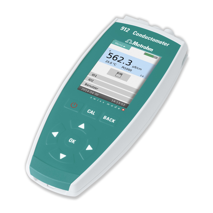
■■■■■■■■■■■■■■■■■■■■■■ 2 Overview of the instrument 2 Overview of the instrument Figure 1 pH Meter/Conductometer - front Connectors / interfaces Sensor holder slot With a cover cap for the USB interface and For mobile applications, a sensor holder may the digital interface. be inserted here. -
Page 18: Instrument Connectors
■■■■■■■■■■■■■■■■■■■■■■ 2.1 Instrument connectors Instrument connectors 2.1.1 912 Conductometer Figure 2 912 Conductometer - connectors Conductivity measuring cell Type B mini USB connector Connection socket for conductivity measur- Connection socket for power supply, data ing cells. transmission and printing. 2.1.2... -
Page 19: 914 Ph/Conductometer Is
■■■■■■■■■■■■■■■■■■■■■■ 2 Overview of the instrument 2.1.3 914 pH/Conductometer IS Figure 4 914 pH/Conductometer (digital) - connectors Conductivity measuring cell pH/mV electrode Connection socket for 854 iConnect for Connection socket for conductivity measur- ing cells. connecting iTrodes. Type B mini USB connector Connection socket for power supply, data transmission and printing. -
Page 20: Application Environment
■■■■■■■■■■■■■■■■■■■■■■ 2.2 Application environment Application environment pH Meter/Conductometer instruments have been designed for use in laboratories and for mobile use indoors or outdoors. The sturdy design meets the requirements in accordance with IP 67 pro- tection marking. The instruments are therefore protected against short- time immersion in water, provided that the respective plugs are plugged in at the sensor connectors. -
Page 21: Mobile Application
■■■■■■■■■■■■■■■■■■■■■■ 2 Overview of the instrument 2.2.2 Mobile application For mobile application, pH Meter/Conductometer instruments can be equipped with a carrying strap and one or two slide-in holders for elec- trodes. Figure 7 pH Meter/Conductometer for mobile application Electrode holder Eyelet for carrying strap The holders can be inserted from both sides (left/right) of the instrument. -
Page 22: Installation
■■■■■■■■■■■■■■■■■■■■■■ 3.1 Unpacking and inspecting the instrument 3 Installation Unpacking and inspecting the instrument 3.1.1 Packaging The instrument is supplied in protective packaging together with the sepa- rately packed accessories. Keep this packaging, as only this ensures safe transportation of the instrument. 3.1.2 Checks Immediately after receipt, check whether the shipment has arrived com-... -
Page 23: Charging The Accumulator
■ Do not attempt to remove the accumulator from the instrument. To ■ replace the accumulator, take the instrument to your nearest author- ized Metrohm Service. Unauthorized replacement of the accumulator may result in a loss of ■ the warranty. -
Page 24: Operation With Power Supply Unit
Accumulator condition The accumulator performance may deteriorate over time. If the operat- ing times are much shorter than usual, take the instrument to the clos- est Metrohm Service to have the accumulator replaced. 3.2.2 Operation with power supply unit You can operate the pH Meter/Conductometer with the supplied power supply unit without restrictions. -
Page 25: Operation Via Usb Connector (Pc)
■■■■■■■■■■■■■■■■■■■■■■ 3 Installation NOTE Charging the accumulator with a power supply The accumulator will not be overcharged if the instrument is used for extended periods with the power supply unit connected. The instru- ment is equipped with a charging controller to protect the accumulator. 3.2.3 Operation via USB connector (PC) NOTE... -
Page 26: Connecting A Printer
Meter/Conductometer is connected to the power supply unit. NOTE Measuring signal interference Inappropriate power supply units of a printer interfere with the measur- ing signal. With the Metrohm USB printer "Neos" (2.141.0100) there is no ■ interference. Only use printers with a grounded power supply unit. ■... -
Page 27: Initial Configuration
■■■■■■■■■■■■■■■■■■■■■■ 3 Installation Figure 8 USB Y cable USB type A USB type B mini Power supply unit connector for power sup- Instrument connector pH Meter/ ply. Conductometer. USB type B Printer connector. Initial configuration 3.5.1 Setting the Language NOTE "Language"... -
Page 28: Setting The Date And Time
■■■■■■■■■■■■■■■■■■■■■■ 3.5 Initial configuration Use the button to change to the menu structures. arrow key to select the Configuration menu struc- Use the ture and use the key to change to the menu structure. Use the arrow key to select the Language menu dialog and use the key to change to the selection dialog. - Page 29 ■■■■■■■■■■■■■■■■■■■■■■ 3 Installation arrow key to select the Date or Time menu dialog Use the and use the key to change to the editing dialog. Date format: YYYY-MM-DD ■ Time format: hh:mm:ss ■ Use the arrow keys to select the required characters and confirm with the key in each case.
-
Page 30: Operation
Editing dialog ■ Selection dialog ■ NOTE Active dialog field The actively selected dialog field is always displayed with the Metrohm green contrast color. In this case, the entry point for the Menu menu structures is selected. ■■■■■■■■ pH Meter/Conductometer... -
Page 31: Figure 9 View - Main Dialog
■■■■■■■■■■■■■■■■■■■■■■ 4 Operation Main dialog The main dialog (example: both measuring channels displayed) is the nor- mal status after the instrument has been switched on. Figure 9 View - main dialog Menu dialog The menu dialog is used for navigating through the functional structures. Menu lines with an arrow contain another, deeper structure with further dialogs. -
Page 32: Figure 11 View - Editing Dialog
■■■■■■■■■■■■■■■■■■■■■■ 4.2 Displays NOTE Capital letters and special characters You can insert capital letters and special characters by holding the key pressed down. Figure 11 View - editing dialog Selection dialog Selection dialogs offer default values for selection in corresponding data fields. -
Page 33: Status Displays
■■■■■■■■■■■■■■■■■■■■■■ 4 Operation Status displays The main dialog displays contain corresponding graphical elements to show instrument and sensor statuses. 4.3.1 Accumulator status The accumulator status is displayed in five stages with colored graphical elements. The accumulator is fully charged and charging is complete. The accumulator is nearly fully charged but still charging. -
Page 34: Sensor Quality For Ph Electrodes
■■■■■■■■■■■■■■■■■■■■■■ 4.4 Control keys 4.3.3 Sensor quality for pH electrodes The sensor quality is indicated with three colored graphical elements. The criteria for the display status are set in the calibration parameters (see Chapter 4.7.4, page 42). The electrode is in a good range with regard to the limit values set. The electrode is close to the limit value range. -
Page 35: Basic Operation
Main dialog with two measuring channels The view with two measuring channels is displayed after the instrument start-up. NOTE This does not apply for the 912 Conductometer, as this instrument has only one measuring channel. NOTE Temperature display The temperature displays on the two measuring channels can only be compared in the same medium. -
Page 36: Main Dialog With One Measuring Channel
■■■■■■■■■■■■■■■■■■■■■■ 4.5 Basic operation Figure 13 Operation - main dialog, two-channel Battery state of charge Menu access (see Chapter 4.3.1, page 23). (see "Accessing the menu structures", page 27). Sensor condition Display measuring channel 1 (see Chapter 4.3.3, page 24). Calibration interval display Display measuring channel 2 Time in days until the next calibration is due. -
Page 37: Operation In The Main Dialog
■■■■■■■■■■■■■■■■■■■■■■ 4 Operation Figure 14 Operation - main dialog, one-channel Battery state of charge Menu access (see Chapter 4.3.1, page 23). (see "Accessing the menu structures", page 27). Sensor condition Measuring channel display (see Chapter 4.3.3, page 24). Calibration interval display Print/save measured value Time in days until the next calibration is due. -
Page 38: Menu Dialog
■■■■■■■■■■■■■■■■■■■■■■ 4.5 Basic operation Use the key to change to the menu structures. Toggling from one-channel to two-channel view The view can be changed in instruments with two measuring channels. Three views can be displayed as follows: Display with both measuring channels. ■... -
Page 39: Editing Dialog
Menu line selected The menu title indicates which menu struc- The selected menu line is always displayed in ture is currently open. the color Metrohm green and in inversed text. Arrow icon The arrow icon indicates that there are fur- ther substructures. -
Page 40: Figure 16 Operation - Editing Dialog
■■■■■■■■■■■■■■■■■■■■■■ 4.5 Basic operation Figure 16 Operation - editing dialog Menu title Menu line Data field Selectable characters Function elements The data entry is accepted with the Entry editing element. The editing dialog is closed without changing the existing data value with the Cancel editing element. -
Page 41: Selection Dialog
■■■■■■■■■■■■■■■■■■■■■■ 4 Operation 4.5.6 Selection dialog In selection dialogs, you can select and apply fixed data values. Figure 17 Operation - selection dialog Menu title Menu line Selectable data values Changing data values The data values of the corresponding menu function can be selected, if required. -
Page 42: Changing The User
■■■■■■■■■■■■■■■■■■■■■■ 4.5 Basic operation 4.5.7 Changing the user The user can be set to two different dialog types in the instrument (see Chapter 4.7.7, page 49). Routine Changing the instrument to the User Routine: 1 Switch to the selection dialog Menu ▶ User ▶ Dialog type 2 Select the Dialog type Routine. -
Page 43: Menu Structures
4 Operation Menu structures pH Meter/Conductometer instruments contain different menu struc- tures depending on the instrument version. These structures are repre- sented in an overview in the following tables: 912 Conductometer ■ (see Chapter 4.6.1, page 34) 913 pH Meter ■... -
Page 44: 912 Conductometer
■■■■■■■■■■■■■■■■■■■■■■ 4.6 Menu structures 4.6.1 912 Conductometer Table 2 912 Conductometer – menu structures Menu Parameters Κ/TDS/Sal/ρ/T Measuring parameters ■ Calibration param. ■ (see Chapter 4.7.2, page 39) Measured values Values ■ Data ■ (see Chapter 4.7.3, page 40) Criterion ■... -
Page 45: 913 Ph Meter
■■■■■■■■■■■■■■■■■■■■■■ 4 Operation 4.6.2 913 pH Meter Table 3 913 pH Meter – menu structures Menu Parameters pH/U/T Measuring parameters ■ Calibration param. ■ Parameters pH/U/T IS (see Chapter 4.7.1, page 38) Measured values Values ■ Data ■ (see Chapter 4.7.3, page 40) Criterion ■... - Page 46 ■■■■■■■■■■■■■■■■■■■■■■ 4.6 Menu structures 4.6.3 914 pH/Conductometer IS Table 4 914 pH/Conductometer IS – menu structures Menu Parameters pH/U/T IS Measuring parameters ■ Calibration param. ■ (see Chapter 4.7.1, page 38) Parameters Κ/TDS/Sal/ρ/T Measuring parameters ■ Calibration param. ■ (see Chapter 4.7.2, page 39) Measured values Values ■...
-
Page 47: 914 Ph/Conductometer
■■■■■■■■■■■■■■■■■■■■■■ 4 Operation 4.6.4 914 pH/Conductometer Table 5 914 pH/Conductometer – menu structures Menu Parameters pH/U/T Measuring parameters ■ Calibration param. ■ (see Chapter 4.7.1, page 38) Parameters Κ/TDS/Sal/ρ/T Measuring parameters ■ Calibration param. ■ (see Chapter 4.7.2, page 39) Measured values Values ■... -
Page 48: Menu Dialogs
■■■■■■■■■■■■■■■■■■■■■■ 4.7 Menu dialogs Menu dialogs 4.7.1 Parameters pH/U/T and Parameters pH/U/T IS The Parameters pH/U/T menu dialog for the parameters Measurement and Calibration is shown below with the structure and the description. Measuring parame- ters ▶ Menu dialog for the Measuring parameters. Selection dialog for selecting the measuring mode. -
Page 49: Parameters Κ/Tds/Sal/Ρ/T
■■■■■■■■■■■■■■■■■■■■■■ 4 Operation Buffer type Selection dialog for selecting the buffer type. Available buffers and their values (see Chapter 7.1, page 66) ■ If required, the preset values may be adjusted for the Special buffer type. ■ Default value: 7 / input range: –19.999 - +19.999 4.7.2 Parameters Κ/TDS/Sal/ρ/T The Parameters Κ/TDS/Sal/ρ/T menu dialog for the parameters Mea-... -
Page 50: Measured Values
■■■■■■■■■■■■■■■■■■■■■■ 4.7 Menu dialogs Default value: 0.40 / input range: 0.40 - 1.00°C ■ Calibration param. ▶ Menu dialog for the Calibration param.. Temperature Editing dialog for manually entering the calibration temperature. Default value: 25.0°C / input range: 0 - 99.9°C ■... - Page 51 ■■■■■■■■■■■■■■■■■■■■■■ 4 Operation save as PC/LIMS ■ The currently saved measured values will be saved on the instrument as PC/ LIMS file (see "PC/LIMS report", page 57). Data Selection dialog to indicate whether the Data are to be printed and/or saved. print: ■...
-
Page 52: Sensors
■■■■■■■■■■■■■■■■■■■■■■ 4.7 Menu dialogs drift-dependent ■ The measured value will be applied when the value is stable according to the drift criterion. The drift thresholds are preset and cannot be changed: – pH measurement: 0.028 pH/min – Potential measurement U/mV: 1.875 mV/min –... - Page 53 ■■■■■■■■■■■■■■■■■■■■■■ 4 Operation NOTE Extent of the menu dialog Depending on the instrument version and the sensor type, not all or only the specific menu lines are available in the instrument's menu dia- log. The overview below includes a description of all menu lines. Menu lines that are available only for pH measurement are marked ■...
- Page 54 ■■■■■■■■■■■■■■■■■■■■■■ 4.7 Menu dialogs Only displayed for iTrodes. Editing dialog for entering/modifying the Serial number. Serial number Only displayed for iTrodes. Editing dialog for entering/modifying the Slope. Slope Default value: 100.00 / input range: 0.10 - 990.00% ■ Editing dialog for entering/modifying pH(0). pH(0) Default value: 7,000 / input range: –99,999 - +99,999 ■...
- Page 55 ■■■■■■■■■■■■■■■■■■■■■■ 4 Operation ■ off: is the default value ■ Editing dialog for entering the lower limit value. Slope lower limit Default value: 95.00 / input range: 1.0 - 999.9% ■ Slope upper Editing dialog for entering the upper limit value. limit Default value: 103.00 / input range: 1.0 - 999.9% ■...
- Page 56 ■■■■■■■■■■■■■■■■■■■■■■ 4.7 Menu dialogs Default value: 100.00 / input range: 0.10 - 999.99% ■ Editing dialog for entering/modifying pH(0). pH(0) Editing dialog for entering/modifying the Cell constant. Cell constant Default value: 1.00/cm / input range: 0.001 - 500/cm ■ Calibration Editing dialog for entering time in days for the Calibration interval.
-
Page 57: Report
■■■■■■■■■■■■■■■■■■■■■■ 4 Operation off: is the default value ■ Editing dialog for entering the lower limit value. c lower limit Default value: 0.400/cm / input range: 0.001 - 500/cm ■ Editing dialog for entering the upper limit value. c upper limit Default value: 0.550/cm / input range: 0.001 - 500/cm ■... -
Page 58: Configuration
■■■■■■■■■■■■■■■■■■■■■■ 4.7 Menu dialogs Seiko (ESC-POS) ■ Roll printer with paper width 110 mm Citizen ESC-POS) ■ Roll printer with paper width 80 mm Custom (ESC-POS) ■ Roll printer with paper width 60 mm Universal (ESC-POS) ■ Universal roll printer with variable settings: –... -
Page 59: User
The default setting ex works is Expert. Old password New password Confirm Service/Diagnosis ▶ Menu dialog with password-protected access for Metrohm Service. Password entry for the Service/Diagnosis menu functions. Password 4.7.7 User The User menu dialog for setting user restrictions and user data is shown below with the description. -
Page 60: Ph Measurement
By default, the calibration parameters are set for calibration with two Metrohm buffer solutions (see Chapter 4.7.1, page 38). If you would like to use other buffers, you have to select the corresponding buffer type and the number of buffer solutions. - Page 61 ■ NOTE Buffer exchange If the buffer solution was not exchanged, then the message 912-181 Same buffer will appear. Exchange the buffer solution and continue the calibration with the key. 3 Result of the calibration The result of the calibration is displayed in a diagram.
-
Page 62: Measurement
■■■■■■■■■■■■■■■■■■■■■■ 4.8 pH measurement 4.8.2 Measurement NOTE Measured value criteria You can set the various criteria for defining the measured value deter- mination as follows (see Chapter 4.7.3, page 40): 1 Selecting the printout criterion If the measured value found is to be directly printed out as a mea- ■... -
Page 63: Conductivity Measurement
■■■■■■■■■■■■■■■■■■■■■■ 4 Operation NOTE Measured value recording Depending on the settings of the measured value criterion, the recording of the measured value may take some time. During the measurement, hold the sensor steady and do not touch the sam- ple vessel with it. For measurements that take longer, we recommend using a stand to secure the sensor in place. -
Page 64: Measurement
■■■■■■■■■■■■■■■■■■■■■■ 4.9 Conductivity measurement Start the calibration with the key. ■ Rinse the conductivity sensor with water and immerse it in the ■ first standard solution and then confirm with the key. The calibration temperature is measured with the connected tem- ■... - Page 65 ■■■■■■■■■■■■■■■■■■■■■■ 4 Operation If the measured value found is to be directly printed out as a mea- ■ sured value report, then you have to set the required printout cri- terion (see Chapter 4.5.3, page 27). 2 Selecting the measured value criterion This criterion defines the conditions as to when the measured ■...
-
Page 66: Issuing Reports/Measured Values
■■■■■■■■■■■■■■■■■■■■■■ 4.10 Issuing reports/measured values 4.10 Issuing reports/measured values The pH Meter/Conductometer supports output of various printouts and data transfers for displaying the calibration and measured values. 4.10.1 Printing out The printouts are divided into various groups: Printing out values directly after generation: ■... - Page 67 The data on the instrument memory can be saved in two data formats: PC/LIMS report Data in PC/LIMS format can be imported into and processed in the Metrohm program tiBase for evaluation. NOTE Data collision Transferring data from several instruments can lead to a data collision in tiBase.
- Page 68 ■■■■■■■■■■■■■■■■■■■■■■ 4.10 Issuing reports/measured values Generating/transferring report data NOTE USB interface If the report data is to be generated while the instrument is connected to the PC, then the connection is briefly interrupted. After the report data has been generated, the connection will be auto- matically established again.
-
Page 69: Operation And Maintenance
Maintenance of the pH Meter/Conductometer is best carried out as part of annual service, which is performed by specialist personnel from Metrohm. A shorter maintenance interval may be necessary if you fre- quently work with caustic and corrosive chemicals. Metrohm Service offers every form of technical advice for maintenance and service of all Metrohm instruments. -
Page 70: Quality Management And Qualification With Metrohm
Maintenance The electronic and mechanical modules of Metrohm instruments can and should be checked by specialist personnel from Metrohm as part of a reg- ular preventive maintenance schedule. Please ask your local Metrohm rep- resentative regarding the precise terms and conditions involved in con- cluding a corresponding maintenance agreement. -
Page 71: Troubleshooting
■■■■■■■■■■■■■■■■■■■■■■ 6 Troubleshooting 6 Troubleshooting General If you experience problems during measurements, then you can check the following aspects to eliminate them: Application Difficult sample matrices or interfering influences may render accurate measurements impossible (e.g. insufficient ionic strength, presence of interfering ions, etc.). -
Page 72: Problems
The measuring input and/ Send the measuring instrument to the ■ or the measuring channel Metrohm Service for inspection and, if nec- is defective. essary, repair. The instrument does The instrument battery is Connect the instrument to the power sup- ■... - Page 73 Measurement takes place Use a suitable sensor. ■ in an organic solution. Non-Metrohm power sup- Use only the supplied power supply unit ■ ply unit used for charging during measurement operation. the battery. The measured value pH calibration is faulty.
-
Page 74: Restarting/Resetting The Instrument
■■■■■■■■■■■■■■■■■■■■■■ 6.3 Restarting/resetting the instrument Problem Cause Remedy No hydrated layer is pres- Hydrate the electrode between the meas- ■ ent on the glass membrane urements. after measurements in water-free solutions. The buffer solutions are not Replace the buffer solutions. ■... -
Page 75: Messages
■■■■■■■■■■■■■■■■■■■■■■ 6 Troubleshooting + ■ Afterwards, a message will be displayed saying that the user data has ■ been deleted. Messages The instruments notify you of possible errors or operation problems with various specific messages. A message as shown in the following example will appear on the current display. -
Page 76: Appendix
The temperature-dependent pH values of the most important commer- cially available pH buffer solutions are stored in pH Meter/Conducto- meter instruments for automatic buffer recognition during pH calibration. In addition to the Metrohm buffer solutions, other reference buffers are also included in the tables. CAUTION... -
Page 77: Metrohm
■■■■■■■■■■■■■■■■■■■■■■ 7 Appendix 7.1.1 Metrohm Table 6 Metrohm buffer solutions Metrohm Temp. (°C) 4.00 7.00 9.00 3.99 7.11 9.27 3.99 7.08 9.18 3.99 7.06 9.13 3.99 7.04 9.08 3.99 7.02 9.04 4.00 7.00 9.00 4.00 6.99 8.96 4.01 6.98 8.93 4.02... -
Page 78: Nist (According To Din Standard 19266, 2000)
■■■■■■■■■■■■■■■■■■■■■■ 7.1 Saved buffer series 7.1.2 NIST (according to DIN standard 19266, 2000) Table 7 NIST buffer solutions NIST (according to DIN standard 19266, 2000) Temp. (°C) 1,680 4,008 6,865 9,184 12,454 4,010 6,984 9,464 13,423 1,668 4,004 6,950 9,392 13,207 1,670 4,001... -
Page 79: Din (According To Din Standard 19267, 2012)
■■■■■■■■■■■■■■■■■■■■■■ 7 Appendix 7.1.3 DIN (according to DIN standard 19267, 2012) Table 8 DIN buffer solutions DIN (according to DIN standard 19267, 2012) Temp. (°C) 1.09 3.06 4.65 6.79 9.23 12.75 1.08 4.67 6.89 9.48 1.08 4.66 6.86 9.43 1.09 3.10 4.66 6.84... -
Page 80: Fisher
■■■■■■■■■■■■■■■■■■■■■■ 7.1 Saved buffer series 7.1.4 Fisher Table 9 Fisher buffer solutions Fisher Temp. (°C) 2.00 4.00 7.00 10.00 4.01 7.13 10.34 1.98 3.99 7.10 10.26 1.98 4.00 7.07 10.19 2.02 3.99 7.05 10.12 2.00 4.00 7.02 10.06 2.00 4.00 7.00 10.00 2.00... -
Page 81: Mettler Toledo
■■■■■■■■■■■■■■■■■■■■■■ 7 Appendix 7.1.5 Mettler Toledo Table 10 Mettler Toledo buffer solutions Mettler Toledo Temp. (°C) 2.00 4.01 7.00 9.21 11.00 7.12 2.03 4.01 9.52 11.90 2.02 4.01 7.09 9.45 11.72 2.01 4.00 7.06 9.38 11.54 2.00 4.00 7.04 9.32 11.36 2.00 4.00... -
Page 82: Merck Certipur 20 / Titrisol
■■■■■■■■■■■■■■■■■■■■■■ 7.1 Saved buffer series 7.1.6 Merck CertiPUR 20 / Titrisol Table 11 Merck CertiPUR 20 / Titrisol buffer solutions Merck CertiPUR 20 Temp. (°C) 2.000 4.000 7.000 9.000 12.000 2.010 4.050 7.130 9.240 12.580 2.010 4.040 7.070 9.160 12.410 2.010 4.020 7.050... -
Page 83: Merck Certipur 25
■■■■■■■■■■■■■■■■■■■■■■ 7 Appendix 7.1.7 Merck CertiPUR 25 Table 12 Merck CertiPUR 25 buffer solutions Merck CertiPUR (25°C) Temp. (°C) 4.00 7.00 9.00 10.00 4.05 7.09 9.22 10.22 4.04 7.08 9.16 10.18 4.02 7.04 9.10 10.10 4.01 7.02 9.06 10.06 4.00 7.00 9.00 10.00... -
Page 84: Beckmann
■■■■■■■■■■■■■■■■■■■■■■ 7.1 Saved buffer series 7.1.8 Beckmann Table 13 Beckmann buffer solutions Beckmann Temp. (°C) 4.00 7.00 10.01 4.00 7.12 10.32 4.00 7.09 10.25 4.00 7.06 10.18 4.00 7.04 10.12 4.00 7.02 10.06 4.00 7.00 10.01 4.01 6.99 9.97 4.02 6.99 9.93 4.03... -
Page 85: Radiometer Analytical
■■■■■■■■■■■■■■■■■■■■■■ 7 Appendix 7.1.9 Radiometer Analytical Table 14 Radiometer Analytical buffer solutions Radiometer Analytical Temp. (°C) 1.679 4.005 7.000 9.180 1.666 4.000 7.118 9.464 1.668 3.998 7.087 9.395 1.670 3.997 7.059 9.332 1.672 3.998 7.036 9.276 1.675 4.001 7.016 9.225 1.679 4.005 7.000... -
Page 86: Baker
■■■■■■■■■■■■■■■■■■■■■■ 7.1 Saved buffer series 7.1.10 Baker Table 15 Baker buffer solutions Baker Temp. (°C) 4.00 7.00 9.00 10.00 4.00 7.13 9.23 10.30 4.00 7.09 9.17 10.24 4.00 7.05 9.10 10.17 4.00 7.03 9.05 10.11 4.00 7.00 9.00 10.05 4.00 6.98 8.96 10.00... -
Page 87: Hamilton Duracal
■■■■■■■■■■■■■■■■■■■■■■ 7 Appendix 7.1.11 Hamilton DURACAL Table 16 Hamilton DURACAL buffer solutions Hamilton DURACAL Temp. (°C) 4.01 7.00 9.21 10.01 4.01 7.09 9.45 10.19 4.00 7.06 9.38 10.15 4.00 7.04 9.32 10.11 4.00 7.02 9.26 10.06 4.01 7.00 9.21 10.01 4.01 6.99 9.16... -
Page 88: Fluka
■■■■■■■■■■■■■■■■■■■■■■ 7.1 Saved buffer series 7.1.12 Fluka Table 17 Fluka buffer solutions Fluka Temp. (°C) 4.000 7.000 9.000 4.030 7.130 9.240 4.025 7.090 9.175 4.020 7.050 9.110 4.010 7.020 9.055 4.000 7.000 9.000 4.000 6.990 8.965 4.000 6.980 8.930 4.000 6.975 8.895 4.000... -
Page 89: Technical Specifications
The following table lists the measuring inputs for each instrument and the corresponding measuring modes. Table 18 Measuring inputs / instrument Instrument Measuring inputs / measuring modes Electrode, Electrode, Conductivity Temperature Reference analog digital 2.912.010 Κ/TDS/Sal /ρ/T 2.913.010 pH/U/T pH/U/T Κ/TDS/Sal 2.914.010 pH/U/T /ρ/T 2.914.020 pH/U/T Κ/TDS/Sal /ρ/T... -
Page 90: Measured Value Memory
■■■■■■■■■■■■■■■■■■■■■■ 8.2 Measured value memory Display interval of the measurement = 1 s Measured value memory Memory size 10,000 measured values, non-volatile memory ■ 10 sensor entries in sensor list ■ TFT display Resolution 320 x 240 pixels (RGB) Display colors 16.7 million Display size 3.5 inches (70.08 x 52.56 mm) -
Page 91: Charging Time
■■■■■■■■■■■■■■■■■■■■■■ 8 Technical specifications Car charger No. 6.2166.500 (optional accessories) adapter Nominal input 12 V DC voltage Output voltage 5 V DC Nominal output 1,000 mA current Charging time Charging time 9 hours with original power supply unit (no. 6.2166.100) and original with power supply USB cable unit... -
Page 92: Housing Specification
■■■■■■■■■■■■■■■■■■■■■■ 8.8 Housing specification Housing specification Protection class IP Dust-resistant and protected against temporary immersion in water 67 / DIN EN 60529 Safety specification This instrument fulfills the following electrical safety requirements: CE marking pursuant to the EU directive: 2014/35/EU (Low Voltage Directive, LVD) ■... -
Page 93: Ambient Temperature
■■■■■■■■■■■■■■■■■■■■■■ 8 Technical specifications 8.11 Ambient temperature Operation 0°C - +40°C (at a max. of 85% humidity) Storage and trans- 0°C - +45°C (at a max. of 85% humidity) port 8.12 Reference conditions Ambient tempera- +25°C (±3°C) ture Relative humidity ≤... - Page 94 Internet. You can download this information using the article number as follows: Downloading the accessories list 1 Type http://partslists.metrohm.com into your Internet browser. The Partslists webpage will be displayed. 2 Select the desired output language.
- Page 95 ■■■■■■■■■■■■■■■■■■■■■■ Glossary Glossary Display field Display fields are menu lines with a designation and a displayed value. Editing dialog In editing dialogs, you can enter or edit values (see "Editing dialog", page 21). The abbreviation IS in instruments and menus stands for Intelligent Sensor from the iTrode line of sensors.
- Page 96 Measured values ...... 40 Connector ........8 Measuring parameters ..38, 39 Control keys ......24 Safety instructions ...... 4 Metrohm Service ...... 59 CSV file ........57 Sales version ....... 2 Salinity ........39 New sensor ......45 Sensor ........3 Date .........
Need help?
Do you have a question about the 912 and is the answer not in the manual?
Questions and answers