Metrohm 940 Professional IC Vario Manual - Short Instructions
Hide thumbs
Also See for 940 Professional IC Vario:

Related Manuals for Metrohm 940 Professional IC Vario


Summary of Contents for Metrohm 940 Professional IC Vario
- Page 1 940 Professional IC Vario 940 Professional IC Vario ONE/SeS/Prep 2 Manual – Short Instructions 8.940.8114EN / v3 / 2023-02-28...
- Page 3 Metrohm AG CH-9100 Herisau Switzerland +41 71 353 85 85 info@metrohm.com www.metrohm.com 940 Professional IC Vario 940 Professional IC Vario ONE/SeS/ Prep 2 2.940.1420 Manual – Short Instructions 8.940.8114EN / v3 / 2023-02-28...
- Page 4 Disclaimer Deficiencies arising from circumstances that are not the responsibility of Metrohm, such as improper storage or improper use, etc., are expressly excluded from the warranty. Unauthorized modifications to the product (e.g. conversions or attachments) exclude any liability on the part of the manufacturer for resulting damage and its consequences.
-
Page 5: Table Of Contents
Connecting the leak sensor ............ 19 Column thermostat ............20 Connecting the eluent bottle ..........20 Connecting the eluent degasser ........22 Installing the high-pressure pump ........23 Installing an inline filter ............. 23 940 Professional IC Vario ONE/SeS/Prep 2 (2.940.1420) ■■■■■■■■... - Page 6 5.11 Injection valve ..............23 5.12 Metrohm Suppressor Module (MSM) ....... 23 5.12.1 Inserting the rotors ..............24 5.12.2 Connecting the Metrohm Suppressor Module (MSM) ..... 25 5.13 Metrohm CO Suppressor (MCS) ........28 5.13.1 Connecting the MCS ............. 28 5.13.2...
- Page 7 Removing the transport locking screws ..........17 Figure 4 Installing the tubing weighting and aspiration filter ......22 Figure 5 Metrohm Suppressor Module (MSM) – Connection capillaries ..26 Figure 6 Connecting the MCS ............... 28 940 Professional IC Vario ONE/SeS/Prep 2 (2.940.1420)
-
Page 9: About This Quick Start Guide
In addition to an introduction, safety instructions and an overview of the instrument, you will also find information about instal- ling and operating the 940 Professional IC Vario ONE/SeS/Prep 2 as well as information regarding the warranty. The comprehensive manual can be downloaded as a PDF file from the Internet. -
Page 10: Introduction
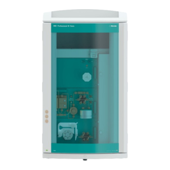
2.1 Instrument description ■■■■■■■■■■■■■■■■■■■■■■ 2 Introduction Instrument description The 940 Professional IC Vario is a professional ion chromatograph. It is dis- tinguished by: Its intelligence: All of the functions are monitored, optimized and docu- ■ mented in an FDA-compatible manner. Intelligent components, such as iColumns, save important data onto a chip. - Page 11 The rotors are not included in the instru- ment's scope of delivery. The rotor required for the application and any adapter that is required must be ordered separately. 940 Professional IC Vario ONE/SeS/Prep 2 (2.940.1420) ■■■■■■■■...
-
Page 12: Accessories And Additional Information
This lowers the background conductivity, improves detection sen- sitivity and minimizes the injection peak and system peak. Detector Metrohm offers a series of different detectors for various analysis tasks. A suitable detector type must be ordered as a separate device. Sample degasser The sample degasser removes gas bubbles and dissolved gases from the sample. -
Page 13: Symbols And Conventions
WARNING This symbol draws attention to a possible hazard due to heat or hot instrument parts. WARNING This symbol draws attention to a possible biological hazard. WARNING Warning of optical radiation 940 Professional IC Vario ONE/SeS/Prep 2 (2.940.1420) ■■■■■■■■... - Page 14 2.3 Symbols and conventions ■■■■■■■■■■■■■■■■■■■■■■ CAUTION This symbol draws attention to possible damage to instruments or instrument parts. NOTICE This symbol highlights additional information and tips. ■■■■■■■■ 940 Professional IC Vario ONE/SeS/Prep 2 (2.940.1420)
-
Page 15: Safety
This instrument is suitable for processing chemicals and flammable sam- ples. Usage of the 940 Professional IC Vario therefore requires the user to have basic knowledge and experience in handling toxic and caustic sub- stances. -
Page 16: Requirements For Operating Personnel
The electrical safety when working with the instrument is ensured as part of the international standard IEC 61010. WARNING Only personnel qualified by Metrohm are authorized to carry out service work on electronic components. ■■■■■■■■ 940 Professional IC Vario ONE/SeS/Prep 2 (2.940.1420) -
Page 17: Tubing And Capillary Connections
Damaged tubing ends lead to leakage. Appropriate tools can be used to loosen connections. Check the connections regularly for leakage. If the instrument is used mainly in unattended operation, then weekly inspections are manda- tory. 940 Professional IC Vario ONE/SeS/Prep 2 (2.940.1420) ■■■■■■■■... -
Page 18: Flammable Solvents And Chemicals
More details about the disposal of your old instrument can be obtained from your local authorities, from waste disposal companies or from your local dealer. ■■■■■■■■ 940 Professional IC Vario ONE/SeS/Prep 2 (2.940.1420) -
Page 19: Overview Of The Device
Offers space for the eluent bottle(s) and Offers space for two embedded detectors additional accessories. and additional accessories. Column holder Metrohm CO Suppressor (MCS) For a third separation column outside the column thermostat. 940 Professional IC Vario ONE/SeS/Prep 2 (2.940.1420) ■■■■■■■■... - Page 20 12 Base tray For the sample preparation. With leak sensor. 13 Peristaltic pump 14 Purge valve For transporting solutions for sample prepa- For purging the high-pressure pump. ration. 15 High-pressure pump 16 Eluent degasser ■■■■■■■■ 940 Professional IC Vario ONE/SeS/Prep 2 (2.940.1420)
-
Page 21: Rear
Up to two vac- tor chamber. uum pumps can be installed in an instru- ment. Only two transport locking screws are used if just one vacuum pump is installed. 940 Professional IC Vario ONE/SeS/Prep 2 (2.940.1420) ■■■■■■■■... - Page 22 For cooling the power supply unit. May Power socket for connecting the power become hot! cable and power switch for switching the instrument on and off. 17 Knurled screws For fastening the removable back panel. ■■■■■■■■ 940 Professional IC Vario ONE/SeS/Prep 2 (2.940.1420)
-
Page 23: Installation
The instrument is equipped with a handle in order to make it easier to transport. The handle can be removed once the instrument is in place in the lab. Accessories You do not need any accessories for the following work steps. 940 Professional IC Vario ONE/SeS/Prep 2 (2.940.1420) ■■■■■■■■... -
Page 24: Removing Transport Locking Screws
These are located at the rear of the instrument and labeled with Transport security screws. Remove these transport locking screws before the initial start-up. Accessories For this step you need: 4 mm hex key (6.2621.030) ■ ■■■■■■■■ 940 Professional IC Vario ONE/SeS/Prep 2 (2.940.1420) -
Page 25: Figure 3 Removing The Transport Locking Screws
Store the transport locking screws in a safe place. Reinsert the transport locking screws each time you transport the instrument a significant dis- tance. CAUTION The pumps may be damaged if you transport the instrument without inserting the transport locking screws. 940 Professional IC Vario ONE/SeS/Prep 2 (2.940.1420) ■■■■■■■■... -
Page 26: Connecting The Drainage Tubing And Leak Sensor
The drainage tubing is connected. ■ The leak sensor connection cable is inserted into the leak sensor ■ connection socket. The 940 Professional IC Vario is switched on. ■ The leak sensor is switched to active in the software. ■ 5.4.1... -
Page 27: Connecting The Leak Sensor
■■■■■■■■■■■■■■■■■■■■■■ 5 Installation Connecting the drainage tubing 5.4.2 Connecting the leak sensor Plugging in the leak sensor connection cable The leak sensor connection cable is coiled up in the base tray. 940 Professional IC Vario ONE/SeS/Prep 2 (2.940.1420) ■■■■■■■■... -
Page 28: Column Thermostat
The tubing adapter for aspiration filter accessory set (6.2744.210) ■ This accessory set contains a filter holder, a clamping screw and tubing weighting. An aspiration filter (6.2821.090) ■ The adsorber tube (6.1609.000) ■ The SGJ clip (6.2023.020) ■ ■■■■■■■■ 940 Professional IC Vario ONE/SeS/Prep 2 (2.940.1420) - Page 29 Always wear gloves when handling the aspiration filter. In order to avoid air bubbles after the installation of the aspiration fil- ter, we recommend pre-rinsing the aspiration filter with water or elu- ent. 940 Professional IC Vario ONE/SeS/Prep 2 (2.940.1420) ■■■■■■■■...
-
Page 30: Connecting The Eluent Degasser
Tighten the aspiration filter to the filter holder. ■ Figure 4 Installing the tubing weighting and aspiration filter Connecting the eluent degasser The eluent degasser is completely connected. No installation work is required. ■■■■■■■■ 940 Professional IC Vario ONE/SeS/Prep 2 (2.940.1420) -
Page 31: Installing The High-Pressure Pump
5.12 Metrohm Suppressor Module (MSM) The suppressor drive of the 940 Professional IC Vario can hold various rotors. The large rotors, such as the SPM Rotor A (6.2835.000), the MSM‑HC Rotor A (6.2842.000) and the MSM-HC Rotor C (6.2842.200) can be inserted directly. -
Page 32: Inserting The Rotors
Connecting piece (6.2835.010) ■ Large rotors can be inserted directly into the rotor housing. CAUTION The rotor may be destroyed during start-up if not inserted correctly. Therefore, follow the following instructions exactly. ■■■■■■■■ 940 Professional IC Vario ONE/SeS/Prep 2 (2.940.1420) -
Page 33: Connecting The Metrohm Suppressor Module (Msm)
5.12.2 Connecting the Metrohm Suppressor Module (MSM) The 3 entries and exits of the suppressor units, numbered 1, 2 and 3 on the connecting piece, each have 2 permanently installed PTFE capillaries. 940 Professional IC Vario ONE/SeS/Prep 2 (2.940.1420) ■■■■■■■■... -
Page 34: Figure 5 Metrohm Suppressor Module (Msm) - Connection Capillaries
Outlet capillary for the regeneration solu- tion; to the waste container. waste rins. rinsing solution Outlet capillary for the rinsing solution; to Inlet capillary for the rinsing solution. the waste container. Recommended installation ■■■■■■■■ 940 Professional IC Vario ONE/SeS/Prep 2 (2.940.1420) - Page 35 To connect the bottles of the auxiliary solutions, you will need the follow- ing accessories: Accessories from the accessory kit: IC Vario/Flex SeS (6.5000.020) ■ Accessories from IC equipment: Dosino Regeneration (6.5330.190) ■ 940 Professional IC Vario ONE/SeS/Prep 2 (2.940.1420) ■■■■■■■■...
-
Page 36: Metrohm Co Suppressor (Mcs)
Suppressor (MCS) ■■■■■■■■■■■■■■■■■■■■■■ 5.13 Metrohm CO Suppressor (MCS) 5.13.1 Connecting the MCS The MCS is connected between the Metrohm Suppressor Module (MSM) and the conductivity detector. Connecting the MCS Figure 6 Connecting the MCS Air aspiration capillary Pressure screw, short (6.2744.070) - Page 37 CW, through which air is aspirated. The CO adsorption cartridge CW is now ready for installation. NOTE The new CO adsorption cartridge CW (6.2837.100) works without attached H O adsorption cartridge. 940 Professional IC Vario ONE/SeS/Prep 2 (2.940.1420) ■■■■■■■■...
-
Page 38: Installing The Conductivity Detector
CW as follows: 5.14 Installing the conductivity detector The 940 Professional IC Vario provides enough space for two detectors and additional accessories in the detector chamber. The detectors are available as separate devices and are supplied with separate manuals. -
Page 39: Installing The Amperometric Detector
5 Installation 5.15 Installing the amperometric detector The 940 Professional IC Vario provides enough space for two detectors and additional accessories in the detector chamber. The detectors are available as separate devices and are supplied with separate manuals. Placing the detector in the instrument Follow the instructions in the chapter Inserting the detector in the manual for the detector. -
Page 40: Peristaltic Pump
2 Select an adapter suitable for the pump tubing. The adapters are included with the pump tubing connection with locking nut and filter (6.2744.180). Installing the pump tubing For this step, you need the following accessories: ■■■■■■■■ 940 Professional IC Vario ONE/SeS/Prep 2 (2.940.1420) - Page 41 Includes a locknut, 3 adapters and a tubing olive with filter holder. 2 × pressure screw, short (6.2744.070) ■ Setting the contact pressure correctly Fully loosen the contact pressure lever , i.e. press it all the way ■ down. 940 Professional IC Vario ONE/SeS/Prep 2 (2.940.1420) ■■■■■■■■...
-
Page 42: Installing The 6-Port Valve
Connecting the instrument to a computer NOTE If the instrument is connected to the computer, then it must be switched off. Accessories For this step, you need the following accessories: USB connecting cable (6.2151.020) ■ ■■■■■■■■ 940 Professional IC Vario ONE/SeS/Prep 2 (2.940.1420) -
Page 43: Connecting The Instrument To The Power Grid
Unplug the power plug immediately if you suspect that moisture has ■ gotten inside the instrument. Only personnel who have been issued Metrohm qualifications may ■ perform service and repair work on electrical and electronic parts. Connecting the power cord... -
Page 44: Initial Start-Up
Also see: MagIC Net Tutorial and online help. 2 Preparing the instrument Ensure that the eluent aspiration tubing is immersed in the eluent ■ and that there is enough eluent in the eluent bottle. ■■■■■■■■ 940 Professional IC Vario ONE/SeS/Prep 2 (2.940.1420) - Page 45 Check whether the detector outlet capillary is connected to the Metrohm Suppressor Module (MSM)'s inlet capillary for rinsing solu- tion (labeled rinsing solution).
-
Page 46: Connecting And Rinsing The Guard Column
(see chapter 5.21, page 36). Until then, replace the guard column and the separation column with couplings (6.2744.040). Accessories For this step, you need the following accessories: Guard column (suitable for separation column) ■ ■■■■■■■■ 940 Professional IC Vario ONE/SeS/Prep 2 (2.940.1420) -
Page 47: Connecting And Rinsing The Separation Column
(follow the information provided by the manufacturer). NOTE Connect the separation column only after the initial start-up of the instrument. Until that point, insert a coupling (6.2744.040) instead of the guard column and separation column. 940 Professional IC Vario ONE/SeS/Prep 2 (2.940.1420) ■■■■■■■■... - Page 48 Manual ▶ Manual control ▶ Pump – Flow: Increase gradually up to the flow rate recommended in the column leaflet. – On Rinse the separation column with eluent for approx. 10 minutes. ■ ■■■■■■■■ 940 Professional IC Vario ONE/SeS/Prep 2 (2.940.1420)
-
Page 49: Conditioning
(arrow has to point in the direction of flow). Ensure that the eluent aspiration tubing is immersed in the eluent ■ and that there is enough eluent in the eluent bottle. 940 Professional IC Vario ONE/SeS/Prep 2 (2.940.1420) ■■■■■■■■... - Page 50 4 Conditioning the system Continue rinsing the system with eluent until the desired stability level for the baseline has been attained . The instrument is now ready for measuring samples. ■■■■■■■■ 940 Professional IC Vario ONE/SeS/Prep 2 (2.940.1420)
-
Page 51: Operation
■■■■■■■■■■■■■■■■■■■■■■ 6 Operation 6 Operation The 940 Professional IC Vario ONE/SeS/Prep 2 is operated solely using the MagIC Net software. You can find information on operating the software in the tutorial for MagIC Net or in the online help. 940 Professional IC Vario ONE/SeS/Prep 2 (2.940.1420) - Page 52 Connector of the cartridge . 28 Also see "6-port valve" ..34 Installation ......28 See also "Injection valve" ..23 Grip Also see "Handle" ....15 Peristaltic pump Installation ......32 ■■■■■■■■ 940 Professional IC Vario ONE/SeS/Prep 2 (2.940.1420)
Need help?
Do you have a question about the 940 Professional IC Vario and is the answer not in the manual?
Questions and answers