Metrohm 917 Manual - Short Instructions
Coulometer
Hide thumbs
Also See for 917:
- Tutorial (67 pages) ,
- Manual (338 pages) ,
- Manual - short instructions (45 pages)
Table of Contents
Advertisement
Quick Links
Advertisement
Table of Contents

Related Manuals for Metrohm 917


Summary of Contents for Metrohm 917
- Page 1 917 Coulometer Manual – Short Instructions 8.917.8002EN / 2015-10-28...
- Page 3 Metrohm AG CH-9100 Herisau Switzerland Phone +41 71 353 85 85 Fax +41 71 353 89 01 info@metrohm.com www.metrohm.com 917 Coulometer Manual – Short Instructions 8.917.8002EN / 2015-10-28 olei...
- Page 4 Technische Dokumentation Metrohm AG CH-9100 Herisau techdoc@metrohm.com This documentation is protected by copyright. All rights reserved. This document has been prepared with great care. However, errors can never be entirely ruled out. Please send comments regarding possible errors to the address above.
-
Page 5: Table Of Contents
Connecting the coulometer to the power supply .... 16 Connecting sensors ............17 5.4.1 Connecting generator electrodes ........... 17 5.4.2 Connecting indicator electrodes ..........19 5.4.3 Connecting a temperature sensor .......... 20 6 Technical specifications Touch screen ............... 22 ■■■■■■■■ 917 Coulometer... - Page 6 Reproducibility ............... 24 Internal stirrer ..............24 Interfaces and connectors ..........24 Power supply ..............25 Safety specifications ............25 Electromagnetic compatibility (EMC) ........ 25 Ambient temperature ............26 Reference conditions ............26 6.10 Dimensions ................26 Index ■■■■■■■■ 917 Coulometer...
- Page 7 Connecting a generator electrode ........... 18 Figure 9 Unscrewing the protective cap from the indicator electrode .... 19 Figure 10 Screwing the electrode cable to the indicator electrode ....19 Figure 11 Connecting an indicator electrode ........... 20 ■■■■■■■■ 917 Coulometer...
-
Page 9: About These Short Instructions
1 About these short instructions This short instruction manual contains important information concerning the 917 Coulometer. In addition to an introduction, safety instructions and an overview of the instrument, you will also find information about the installation of the coulometer. -
Page 10: Introduction
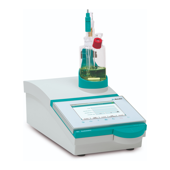
The upper side of the housing offers space for the titration cell. Thanks to its compact construction, you can use the 917 Coulometer in a small space as a stand-alone titrator. -
Page 11: Connectors
For connecting tubing, for replacing reagent using the built-in pump. 2.1.3 Intended use The 917 Coulometer is designed for usage as a titrator in analytical labora- tories. Its main application field is coulometric Karl Fischer titration. This instrument is suitable for processing chemicals and flammable sam- ples. -
Page 12: Symbols And Conventions
WARNING This symbol draws attention to a possible biological hazard. CAUTION This symbol draws attention to possible damage to instruments or instrument parts. NOTE This symbol highlights additional information and tips. ■■■■■■■■ 917 Coulometer... -
Page 13: Safety Instructions
The electrical safety when working with the instrument is ensured as part of the international standard IEC 61010. WARNING Only personnel qualified by Metrohm are authorized to carry out service work on electronic components. WARNING Never open the housing of the instrument. The instrument could be damaged by this. -
Page 14: Tubing And Capillary Connections
Set up the instrument in a well-ventilated location (e.g. fume cup- ■ board). Keep all sources of flame far from the workplace. ■ Clean up spilled liquids and solids immediately. ■ Follow the safety instructions of the chemical manufacturer. ■ ■■■■■■■■ 917 Coulometer... -
Page 15: Recycling And Disposal
The correct disposal of your old equipment will help to prevent negative effects on the environment and public health. More details about the disposal of your old equipment can be obtained from your local authorities, from waste disposal companies or from your local dealer. ■■■■■■■■ 917 Coulometer... -
Page 16: Overview Of The Instrument
Fixed key [STOP] 10 Fixed key [START] Cancels the running determination. Starts a determination. 11 Magnetic stirrer For attaching the titration vessel holder. ■■■■■■■■ 917 Coulometer... -
Page 17: Rear
For connecting temperature sensors (Pt1000 or NTC). Two B sockets, 2 mm. MSB connector (MSB 1 and MSB 2) Generator electrode connector (Gen.) Metrohm Serial Bus. For connecting external For connecting the generator electrode. dosing devices, stirrers or a Remote Box. Mini DIN, 8-pin. -
Page 18: Installation
Place the instrument in a location of the laboratory which is suitable for operation, free of vibrations, protected from corrosive atmosphere, and contamination by chemicals. The instrument should be protected against excessive temperature fluctu- ations and direct sunlight. ■■■■■■■■ 917 Coulometer... -
Page 19: Setting Up The Titration Cell For Coulometry
2 Insert the 6.1464.320 titration cell into the titration vessel holder. 5.2.2 Preparing the titration cell Filling the adsorber tube Before setting up the titration cell, the 6.1403.030 adsorber tube has to be filled with 6.2811.000 molecular sieve. Proceed as follows: ■■■■■■■■ 917 Coulometer... -
Page 20: Figure 2 Filling The Adsorber Tube
4 Seal the adsorber tube with the appropriate cover. NOTE Note that the molecular sieve must be replaced at regular intervals. Each time you refill the adsorber tube with molecular sieve, you can, for example, write the date directly on the adsorber tube. ■■■■■■■■ 917 Coulometer... -
Page 21: Figure 3 Equipping The Titration Cell
Make sure that the edges of the ground-joint sleeves are cut to size cleanly and that there are no fringes. The ground-joint sleeves must not protrude at the lower edge of the ground-joint opening. 3 Insert the 6.1403.030 adsorber tube into the generator electrode. ■■■■■■■■ 917 Coulometer... - Page 22 6.2738.000 funnel. The level of the anolyte should be roughly 1 to 2 mm above the level of the catholyte. 3 Close the remaining ground-joint opening on the right with the 6.1437.000 ground-joint stopper (with ground-joint sleeve attached). ■■■■■■■■ 917 Coulometer...
-
Page 23: Mounting The Addition And Aspiration Tube
6 Connect the tubing for the aspiration of the titration cell at the lower connector of the addition and aspiration tube (6). Details regarding how to connect the addition tubing and the aspiration tubing can be found in the tutorial for the 917 Coulometer. ■■■■■■■■ 917 Coulometer... -
Page 24: Connecting The Coulometer To The Power Supply
5.3 Connecting the coulometer to the power supply Connecting the coulometer to the power supply Connecting the power supply unit The 917 Coulometer has an external power supply unit for a 24 V power supply (DC). This is connected to the power socket of the coulometer. WARNING An incorrect supply voltage can damage the instrument. -
Page 25: Connecting Sensors
5.4.1 Connecting generator electrodes Screwing the electrode cable to the generator electrode 1 Unscrew the protective cap from the generator electrode. Figure 6 Unscrewing the protective cap from the generator elec- trode ■■■■■■■■ 917 Coulometer... -
Page 26: Figure 7 Screwing The Electrode Cable To The Generator Electrode
NOTE The electrode cable is protected against accidental disconnection of the cable by means of a pull-out protection. If you wish to pull out the plug again, you first need to pull back the outer plug sleeve. ■■■■■■■■ 917 Coulometer... -
Page 27: Connecting Indicator Electrodes
2 Tighten the 6.2104.020 electrode cable to the indicator electrode. 6.2104.020 Figure 10 Screwing the electrode cable to the indicator electrode Connecting the electrode cable to the coulometer 1 Plug the electrode plug into the Ind. socket of the coulometer. ■■■■■■■■ 917 Coulometer... -
Page 28: Connecting A Temperature Sensor
A temperature sensor of the Pt1000 or NTC type can be connected to the Temp. connector. Connect the temperature sensor as follows: 1 Insert the plugs of the temperature sensor into the Temp. sockets of the coulometer. ■■■■■■■■ 917 Coulometer... - Page 29 ■■■■■■■■■■■■■■■■■■■■■■ 5 Installation NOTE Always insert the red plug into the red socket. This is the only way that shielding against electrical interference can be ensured. ■■■■■■■■ 917 Coulometer...
-
Page 30: Technical Specifications
– Acetone – Chloroform – Formamide – Sulfuric acid c(H ) = 2 mol/L – Hydrochloric acid c(HCl) = 2 mol/L – Caustic soda c(NaOH) = 2 mol/L – Composite 5 – 1-butanol – 1-hexanol – Decanol ■■■■■■■■ 917 Coulometer... -
Page 31: Measuring Inputs
Pt1000 ±0.2 °C (Applies for measuring range –20 - +150 °C; ±1 digit; without sensor error, under reference conditions) ±0.6 °C (Applies for measuring range +10 - +40 °C; ±1 digit; without sensor error, under reference conditions) ■■■■■■■■ 917 Coulometer... -
Page 32: Determination Range
For connection to a data network (LAN). One connector each for: Sensor connectors Generator electrode ■ Indicator electrode ■ Temperature sensors (Pt1000 or NTC) ■ Two connection For connecting tubing for aspirating solvent and extracting the con- nipples tents of the titration cell. ■■■■■■■■ 917 Coulometer... -
Page 33: Power Supply
EN/IEC 61000-6-3 ■ EN 55011 / CISPR 11 ■ Immunity EN/IEC 61000-6-2 ■ EN/IEC 61000-4-2 ■ EN/IEC 61000-4-3 ■ EN/IEC 61000-4-4 ■ EN/IEC 61000-4-5 ■ EN/IEC 61000-4-6 ■ EN/IEC 61000-4-11 ■ EN/IEC 61000-4-14 ■ EN/IEC 61000-4-28 ■ ■■■■■■■■ 917 Coulometer... -
Page 34: Ambient Temperature
6.10 Dimensions 193 mm Width Height (without 145 mm titration vessel holder) Height (with titra- 230 mm tion vessel holder) Depth 448 mm Weight (including 6,020 g power supply unit) Material Housing Base Steel, stainless, coated ■■■■■■■■ 917 Coulometer... -
Page 35: Index
Temperature sensor ....9, 20 KFC ..........2 Connect ......17 Titration cell Electrode Equip ........13 Connect ......17 Metrohm Serial Bus ....9 Fill ........14 Electrostatic charge ....6 Molecular sieve Insert ........11 Ethernet connector ..... 9 Replace ......12 Set up ........
Need help?
Do you have a question about the 917 and is the answer not in the manual?
Questions and answers