Table of Contents
Advertisement
Quick Links
Advertisement
Table of Contents

Related Manuals for Metrohm 757 VA Computrace


Summary of Contents for Metrohm 757 VA Computrace
- Page 1 757 VA Computrace Hardware Manual 8.757.1013 METROHM Ltd. CH-9101 Herisau...
- Page 2 CH-9101 Herisau/Schweiz Internet www.metrohm.com E-Mail info@metrohm.ch 757 VA Computrace Hardware Manual 8.757.1013 14.09.2001 / dö...
-
Page 3: Table Of Contents
Setting up the instrument ...............13 3.1.1 Packaging................13 3.1.2 Check..................13 3.1.3 Location ................13 Installation of the 757 VA Computrace Stand......14 3.2.1 Mains cable and mains connection........14 3.2.2 Switching the instrument on/off ..........14 3.2.3 Connection to the PC ............15 3.2.4... - Page 4 Front of the 757 VA Computrace Stand ..........8 Fig. 2: Rear of the 757 VA Computrace Stand ........... 9 Fig. 3: Right side view of the 757 VA Computrace Stand ........ 10 Fig. 4: Left side view of the 757 VA Computrace Stand........10 Fig. 5: Connection to PC ..................
-
Page 5: Introduction
1.1 Instrument description 1 Introduction Instrument description 757 VA Computrace is a PC-controlled system for voltammetry, which consists of the following parts: 1.757.0010 VA Computrace Stand with accessories 6.5326.000 VA Computrace Interface 6.2135.010 Connecting Cable 6.6032.100 VA Computrace Software 2.0 For a detailed description of the PC software «VA Computrace 2.0»... -
Page 6: Information About The Instructions For Use
1.2.1 Organization These 8.757.1013 Hardware Manual for the 757 VA Computrace Stand provide a comprehensive overview of the installation, operation, and technical specifications of these instruments. The Instructions for Use are divided into the following 6 sec-... -
Page 7: Notation And Pictograms
Caution This symbol marks important information. First read the associ- ated directions before you con- tinue. Comment This symbol marks additional information and tips. 757 VA Computrace – Hardware... -
Page 8: Support Documentation
Of Metrohm's approximately 200 Application Bulle- tins, ca. 60 refer to Polarography and Voltammetry. All these Application Bulletins are available on request free of charge from your Metrohm supplier. The examples listed here substantiate the versatility of the polarographic and volt- ammetric methods for a range of applications including both inorganic and organic substances. - Page 9 Polarographic determination of riboflavin (vitamin B Determination of ultratrace levels of platinum by stripping voltammetry Standard methods in water analysis – use of Metrohm instruments Polarographic determination of pyridoxine (vitamin B Determination of the total arsenic content by stripping voltammetry at the rotating...
-
Page 10: Application Notes
Determination of zinc, cadmium, lead and copper by anodic stripping voltam- metry using carbon electrodes Voltammetric determination of titanium and uranium Validation of Metrohm VA instruments using Standard Operating Procedures 1.3.2 Application Notes The «Application Notes» present application information in concentrated form. In the field of voltammetry, there are at present approximately 120 Application Notes (in English) which can be viewed in the Internet under «... -
Page 11: Parts And Controls
2 Parts and controls In this section you will find the numbers and designations of the parts and controls of the 757 VA Computrace Stand. The numbering applies throughout the instructions for use, i.e. bold numbers in the text (e.g. -
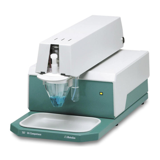
Page 12: Fig. 1: Front Of The 757 Va Computrace Stand
2 Parts and controls Fig. 1: Front of the 757 VA Computrace Stand Cover of measuring head arm Mains pilot lamp hinged lit up when instrument switched Stopper (6.2709.080) Measuring vessel to close the pipetting opening when measuring head arm is... -
Page 13: Fig. 2: Rear Of The 757 Va Computrace Stand
P = 26W STANDBY Remote PC Interface Made by Metrohm Herisau Switzerland Fig. 2: Rear of the 757 VA Computrace Stand Connection for inert Mains switch (on/off) gas lead-off on/off switching of instrument (the pilot lamp 5 is lit up when... -
Page 14: Fig. 3: Right Side View Of The 757 Va Computrace Stand
2 Parts and controls Fig. 3: Right side view of the 757 VA Computrace Stand (fully equipped) 50 49 48 46 31 45 44 43 28 42 39 Fig. 4: Left side view of the 757 VA Computrace Stand (fully equipped) -
Page 15: Fig. 6: Measuring Head Arm
Auxiliary electrode PTFE tube (6.1819.000) details, see section 3.6 (attached) Dummy stopper (6.1446.040) 4-way microtip (6.1824.000) for delivery of solutions; with 4 lengths Dummy stopper (6.1446.040) of PTFE tubing with connecting nipples for 765 Dosimat 757 VA Computrace – Hardware... - Page 16 (RC element) Dummy cell connection ”RE” Dummy cell connection ”AE” Slotted screw for controlling the tapping power in the DME case Note: The factory setting should not be changed without good reason! 757 VA Computrace – Hardware...
-
Page 17: Installation
3.1.3 Location Place the 757 VA Computrace on a laboratory bench in a position suitable for op- eration and which is free from vibrations, protected against corrosive atmospheres and contamination by chemicals. The drip pan 7 (6.2711.040) has to be placed at the front side of the 757 VA Computrace Stand to catch drops (see Fig. -
Page 18: Installation Of The 757 Va Computrace Stand
Stand (see Fig. 2). 3.2.2 Switching the instrument on/off The 757 VA Computrace Stand is switched on and off using mains switch 12. When the instrument is switched on, the pilot lamp 5 lights up. 757 VA Computrace – Hardware... -
Page 19: Connection To The Pc
3.2 Installation of the 757 VA Computrace Stand 3.2.3 Connection to the PC The 757 VA Computrace Stand is connected to the PC via 6.2155.000 VA Com- putrace Interface. Proceed as follows: Software installation • Switch on PC and start operating system (Windows™ 2000) without connection of the VA Computrace Interface via USB cable. -
Page 20: Equipping The Measuring Head
The fixtures inserted in the openings and connections of the measuring head 20 in the 757 VA Computrace Stand depend on the working electrode selected (MME or DME) (see Fig. 6). The fully equipped measuring head for operation with a multi- mode electrode is illustrated in section 2 (Figs 3 and 4), that for operation with a ro- tating disk electrode in section 3.4 (Fig. - Page 21 3.2 Installation of the 757 VA Computrace Stand 66 67 Fig. 6: Measuring head arm Measuring head arm Threaded opening for nipple 23 (6.2730.030) with dummy Measuring head stopper or 4-way microtip 26 (6.1824.000) Opening for auxiliary electrode 39 (6.0343.000 Pt Opening auxiliary electr.
- Page 22 • Slide measuring vessel 6 into holder 3 from the front and fill with analyte solution or dist. H O (storage solution) until the tips of the MME and the reference electrode are immersed in the liquid. • Lower measuring head arm 19 and cover 1. 757 VA Computrace – Hardware...
-
Page 23: Inert Gas Connection
The scheme for deaeration of the analyte solution and the inert gas connections at the 757 VA Computrace Stand needed for operation of the MME is shown in Fig. 7. The inert gas connections are established as follows: Fill gas wash bottle •... -
Page 24: Fig. 7: Scheme Showing The Inert Gas Connections
3 Installation Fig. 7: Scheme showing the inert gas connections at the 757 VA Computrace Stand Gas wash bottle (6.2405.030) for inert gas supply (must be filled only halfway with dist. H O or supporting electrolyte, see also Fig. 3) Slotted screw for controlling the inert gas flow for deaeration (see also Fig. -
Page 25: Multi-Mode Electrode (Mme)
The mercury drops formed at the end of the capillary are very small and stable and thus afford a very good signal/noise ratio. The mercury hermetically sealed in the reservoir comes into contact only with inert gas and other inert materials and suf- fices for around 200'000 drops. 757 VA Computrace – Hardware... -
Page 26: Fig. 8: Multi-Mode Electrode
Screw thread for retaining nut 87 Insert ring (4.420.3011) Sealing ring (4.420.2800) made of silicone rubber Locking ring (4.420.2870) Retaining nut (4.420.2850) Glass capillary (6.1226.030) Screw connection Fig. 8: Multi-mode electrode electrical contact for "WE" electrode cable 757 VA Computrace – Hardware... -
Page 27: Filling The Mme With Mercury
• Place multi-mode electrode 17 with the capillary opening facing upwards in the electrode holder 93 (see Fig. 9). Fig. 9: Adding the mercury Multi-mode electrode Drip pan (6.2711.030) (6.1246.0020) Syringe (6.2816.020) Electrode holder (6.2615.030) Needle (6.2816.030) 757 VA Computrace – Hardware... -
Page 28: Mounting The Capillary
(section 3.3.5). To fill the mounted glass capillary 88 (section 3.3.3) with Hg without vacuum, pro- ceed as follows: 757 VA Computrace – Hardware... - Page 29 Install multi-mode electrode in 757 VA Computrace Stand • With the measuring head arm 19 tilted back, slide the empty measuring vessel 6 into the holder 3 of the 757 VA Computrace Stand and then lower the measuring head arm 19.
-
Page 30: Filling The Capillary Using Vacuum
• Mount filling tubing 94 with filling cone 95 on glass capillary 88. • Connect filling tubing 94 with tubing coupling 97 to the two gas wash bottles 96 and the vacuum pump (see Fig. 10). 757 VA Computrace – Hardware... -
Page 31: Fig. 10: Setting Up The Filling Station
Multi-mode electrode Filling tubing (6.1817.000) (6.1246.0020) Glass capillary (6.1226.030) Filling cone (4.420.2860) (part of the filling tubing 94) Drip pan (6.2711.030) Gas wash bottle Electrode holder (6.2615.030) Tubing coupling (6.1809.000) (part of the filling tubing 94) 757 VA Computrace – Hardware... - Page 32 Install multi-mode electrode in 757 VA Computrace Stand • With measuring head arm 19 tilted back, push empty measuring vessel 6 into the holder 3 of the 757 VA Computrace Stand and then lower meas- uring head arm 19. • Carefully insert multi-mode electrode 17 in opening 55 of the measuring head 20 (during insertion, the tip of the capillary 88 must not touch the measuring head) and push in as far as it will go.
- Page 33 3.3 Multi-mode electrode (MME) 10 Pressurize the MME • Switch on 757 VA Computrace Stand with mains switch 12 (the 757 VA Computrace Stand must first be installed properly as described in section 3.2). • Start the VA Computrace program and click on...
-
Page 34: Storing The Mme
This prevents blockage of the capillary by crystallized salts. An electrode treated in this manner can be taken out of the 757 VA Computrace Stand after a few hours and stored in air for a lengthy period without suffering any damage. -
Page 35: Changing The Capillary
Changing the capillary Contamination of the glass capillary can necessitate its replacement. In such a case, proceed as follows: Remove multi-mode electrode from 757 VA Computrace Stand • Unscrew FEP tubing 30 and 38 from the MME, disconnect electrode cable 16 from MME. -
Page 36: Cleaning The Mme
If the mercury in the multi-mode electrode is contaminated and this leads to distur- bances, the MME must be cleaned and refilled with ultrapure mercury. Proceed as follows: Remove multi-mode electrode from 757 VA Computrace Stand • Unscrew FEP tubing 30 and 38 from the MME, disconnect electrode cable 16 from MME. - Page 37 • Screw retaining nut 87 by hand into screw thread 83 until a slight resis- tance is felt. Add mercury Proceed as described in section 3.3.2. 10 Mount new capillary Proceed as described in section 3.3.3. 11 Fill capillary Proceed as described in section 3.3.4 or section 3.3.5. 757 VA Computrace – Hardware...
-
Page 38: Rotating Disk Electrode (Rde)
The rotating disk electrode (RDE) is available as an option and can be used in place of the MME in the 757 VA Computrace Stand with different electrode tips as a working electrode. The following accessories have to be ordered (see also section 6.2):... -
Page 39: Fig. 12: Measuring Head Arm With Rotating Disk Electrode (Rde)
FEP tubing 30 and 38 FEP tubing (6.1805.180) Electrode tip (6.1204.XXX) for RDE Drive wheel of drive motor Drive shaft (6.1246.000) for RDE FEP tubing (6.1805.090) for inert gas lead-off (attached) 757 VA Computrace – Hardware... -
Page 40: Reference Electrode
Electrical connection for cable "AE" Vent opening Ag/AgCl filling Electrolyte compartment with internal electrolyte Diaphragm support made of PCTFE Diaphragm Vent opening Electrolyte compartment with bridge electrolyte Diaphragm Fig. 13: Construction of the reference electrode 757 VA Computrace – Hardware... -
Page 41: Startup Procedure
The electrolyte solution thus displaced is ex- pelled through the vent opening 109. Install reference electrode in 757 VA Computrace Stand and connect • Insert reference electrode 22 in opening 58 of the measuring head 20 (see Fig. -
Page 42: Auxiliary Electrode
Startup procedure The 6.0343.000 Pt auxiliary electrode supplied as standard can be inserted directly in the 757 VA Computrace Stand (→ 2), whereas the GC auxiliary electrode avail- able as an option must first be assembled (→ 1): Assembly of the GC auxiliary electrode •... -
Page 43: Stirrer
Assemble stirrer • Screw stirrer tip 42 firmly to drive shaft 24. Insert stirrer in 757 VA Computrace Stand and connect • Insert complete stirrer in opening 60 of the measuring head 20 as far as it will go (see Fig. 6). -
Page 44: Connection Of 765 Dosimats
The predecessor model 665 Dosimat can also be connected instead of the 765 Dosimat. Up to five 765 Dosimats can be attached to the 757 VA Computrace Stand for the automatic addition of standard and auxiliary solutions. For the connection of 1 or 2 Dosimats, the 6.2141.080 Cable is used, for the connection of up to 5 Dosimats, the... -
Page 45: Tubing Connection
For the addition of standard or auxiliary solutions into the measuring vessel of the 757 VA Computrace Stand the 4-way microtip 26 (6.1824.000) can be used. It is fit- ted with 4 lengths of PTFE tubing with connection nipples for direct attachment to the Exchange unit of the 765 Dosimat. - Page 46 • Check if there are air bubbles left in the glass cylinder of the exchange unit. If this is the case, repeat the flushing procedure by clicking the button. • Close the window. DOSIMAT CONTROL 757 VA Computrace – Hardware...
-
Page 47: Connection Of The 813 Compact Autosampler
3.9 Connection of the 813 Compact Autosampler Connection of the 813 Compact Autosampler With the 813 Compact Autosampler connected to the 757 VA Computrace Stand, max. 18 samples can be transferred to the measuring vessel at the 757 VA Com- putrace Stand. -
Page 48: Fig. 15: Electrical Connection Of The 813 Compact Autosampler
6.1805.530 6.1805.180 6.1602.105 Aspiration pump 6.1618.050 Waste 6.1819.020 (10 cm) 6.1805.530 6.1819.010 (3 cm) 6.1819.010 (2 cm) 2x6.1820.020 6.1826.100 6.1819.010 (2 cm) 6.1819.010 2x6.1820.050 Fig. 16: Tubing connections for operation of the 813 Compact Autosampler 757 VA Computrace – Hardware... -
Page 49: Fig. 17: Installation Of Accessories For Rinsing And Siphoning Off
PTFE tube (6.1819.010) Gas wash bottle (6.2405.030) for siphoning-off the waste solution for separating mercury from the waste solution (attached) PTFE tube (6.1819.010) for siphoning off the waste solution from gas wash bottle 44 (attached) 757 VA Computrace – Hardware... -
Page 50: Tubing Connections
3 Installation 3.9.2 Tubing connections For operation of the 757 VA Computrace Stand with 813 Compact Autosampler and 772 Pump Units, the accessories and tubing connections must be installed accord- ing to Fig. 16. Proceed as follows: Install accessories at 757 VA Computrace Stand •... - Page 51 • Screw a 6.1805.530 FEP tubing into this opening of the 6.1602.105 siphon. • Attach the other end of the 6.1805.530 FEP tubing at the lower end of the pump tubing of the rinsing pump (see Fig. 16). 757 VA Computrace – Hardware...
-
Page 52: Software Settings
3 Installation 3.9.3 Software settings Before putting into operation the 757 VA Computrace Stand with the 813 Compact Autosampler, the following settings have to be made in the "757 VA Computrace 2.0" software program: Set Dosimat parameters • Click on... - Page 53 GENERAL SETTINGS • Close the "757 VA Computrace 2.0" program and restart it. Test automation parameters • Fill two sample vessels with water and place them one after the other on the sample rack of the 813 Compact Autosampler.
-
Page 54: Operation Of The 813 Compact Autosampler
• Switch on Dosimats and 757 VA Computrace Stand. • Switch on 813 Compact Autosampler and 731 Relay Box. • Switch on PC. • Start 757 VA Computrace software (see Software Manual, section 2.2). Load and modify method • Click on MAIN WINDOW / Mode / Determination •... -
Page 55: Safety
4.1 Electrical safety 4 Safety Electrical safety While electrical safety in the handling of the 757 VA Computrace Stand is assured in the context of the specifications IEC 61010-1 (protection class 1), the following points should be noted: • Mains connection Setting mains connection must be effected in accordance with the instructions in section 3.2.1. -
Page 56: Safety Considerations Concerning Mercury
Θ = 20 ° C) Electrical conductivity 1.044·10 S/cm Odor threshold mg/m Threshold limit value (TLV) for air for mercury mg/m [4, 7] for organic mercury com- 0.01 mg/m [2, 4, 7] pounds (calculated as Hg) 757 VA Computrace – Hardware... -
Page 57: Toxicity Of Mercury And Its Compounds
This can be done by collecting the analysis solutions in a large vessel and then decanting, by filtering the analysis solutions or by siphoning off the mercury using vacuum. 757 VA Computrace – Hardware... - Page 58 − with silver (Ag): Metrohm drop catcher Type 6.2406.000 which is included in the standard outfit of the 757 VA Computrace Stand − with tin (Sn): e.g. the thin tin foil supplied by Merck, Darmstadt/FRG −...
-
Page 59: References Dealing With Mercury
J. Chem Educ. 55 (1978), Fasc 11., 734 [14] Bergmeyer, H.U. Vollautomatische Quecksilber-Waschapparatur für den Laboratoriumsgebrauch Chem. Ing. Techn. 22 (1950), 330 [15] Hamilton, P.B. Continuous Mercury Still Anal. Chem. 23 (1951), 1526 [16] Quecksilberreinigung GIT 6 (1962), 351 757 VA Computrace – Hardware... - Page 60 4 Safety 757 VA Computrace – Hardware...
-
Page 61: Technical Data
Voltage resolution 150 µV Input impedance(RE) R ≥ 1·10 Ω Input Bias Current (RE) ± 10 pA Noise typ. 200 pA Circuit for measurement of the noise: 100 nF Measurement mode: Differential Pulse (method used: DPNoise.mth) 757 VA Computrace – Hardware... -
Page 62: Current Measurement
± 5 % Speed constancy Reference electrode (RE) Construction double-junction; 6.0728.0X0 Ag/AgCl Ref. system + 6.1245.010 Electrolyte vessel to be filled by user Reference system Ag/AgCl/c(KCl) = 3 mol/L Diaphragm ceramic diaphragm; diameter = 3 mm 757 VA Computrace – Hardware... - Page 63 6.1457.210 measuring vessel made of glass with thermostat jacket for sample changer operation (option); working volume = 10 ... 90 mL Dummy Cell Checking the 757 VA Computrace Stand Determination of the signal/noise ratio Connections auxiliary electrode reference electrode WE-L...
-
Page 64: Mains Connection
Voltage 100...240 V Frequency 50...60 Hz Power consumption 26 W 2 × 1.0 ATH (to be replaced by Metrohm Service only Fuse using the same type). Additional electronic overload protection. Safety specifications Construction/testing According to IEC 61010 / EN 61010 / UL 3101-1,... -
Page 65: Appendix
(double-junction construction, assembly, see section 3.5.2). The Ag/AgCl reference system is supplied with a screwed-on holder filled with c(KCl) = 3 mol/L. 6.1204.090 Stirrer tip (PTFE) ∅7 Together with the 6.1246.010 Drive shaft forms the stirrer. 757 VA Computrace – Hardware... - Page 66 6.1246.020 Multi-mode electrode incl. 2 O-rings NBR (nitril rubber) Together with the 6.1226.030 glass capillary forms a complete working electrode. 6.1247.020 Sealing needle for 6.1246.020 Multi-mode electrode Set of 3 757 VA Computrace – Hardware...
- Page 67 Type CEE (7), VII (D…) ......6.2122.040 Type CEE (22), V Type NEMA 5-15 (USA…) ....6.2122.070 6.2135.010 Connection cable to VA Com- putrace Interface Connection cable VA Computrace Interface – 757 VA Computrace Stand. 757 VA Computrace – Hardware...
- Page 68 757 VA Computrace Stand ∅53.2 6.2709.080 Stopper For closing the pipetting aperture of the 757 VA Computrace Stand 6.2711.030 Drip pan made of PS (polystyrene) For filling the Multi-mode electrode with mercury 757 VA Computrace – Hardware...
- Page 69 Registration card (German/English) for PC program «757 VA Computrace 2.0» 8.757.2003 "VA Application Notes" (English) 8.757.5003 Metrohm Monograph "Practical voltammetry" (English) 8.757.8023 Software Manual (English) Instructions for Use for PC program «757 VA Computrace 2.0» 757 VA Computrace – Hardware...
-
Page 70: 2.757.0120 Va Computrace
Type CEE (22), V Type NEMA 5-15 (USA…)....6.2122.070 6.2135.010 Connection cable to VA Com- putrace Interface Connection cable VA Computrace Interface – 757 VA Computrace Stand. 6.2301.100 Lead standard solution ρ (Pb ) = 1.000 ± 0.003 g/L plastic bottle, volume V = 50 mL To perform the test methods. - Page 71 Registration card (German/English) for PC program «757 VA Computrace 2.0» 8.757.2003 "VA Application Notes" (English) 8.757.5003 Metrohm Monograph "Practical voltammetry" (English) 8.757.8023 Software Manual (English) Instructions for Use for PC program «757 VA Computrace 2.0» 757 VA Computrace – Hardware...
-
Page 72: Options
Together with the 6.1247.000 glassy carbon rod forms the GC auxiliary electrode. ∅2.1 6.1246.000 Drive shaft for rotating disk electrode incl. 2 O-rings FPM (Viton Together with the 6.1204.XXX electrode tips forms the rotating disk electrode (RDE). 757 VA Computrace – Hardware... - Page 73 MME gas lines not used in operation with the RDE. 6.2802.000 Polishing kit for mechanical regeneration of the active surface of 6.1204.XXX electrode tips 1 × 2 g α-Al (0.3 µm) comprising: 1 × polishing cloth 757 VA Computrace – Hardware...
- Page 74 V = 50 mL 6.2141.080 Connecting cable for 765 Dosimats Connecting cable 2 × 765 Dosimat – 757 VA Computrace Stand. 6.9921.170 Connecting cable for 765 Dosimats Connecting cable 5 × 765 Dosimat – 757 VA Computrace Stand.
-
Page 75: Warranty
Metrohm from any liability to pay compensation. If any instruments and parts have to be returned, the original packaging should be used if at all possible. -
Page 76: Eu Declaration Of Conformity
6 Appendix EU Declaration of conformity EU Declaration of Conformity The METROHM AG company, Herisau, Switzerland hereby certifies, that the in- strument: 757 VA Computrace meets the requirements of EC Directives 89/336/EWG and 73/23/EWG. Source of the specifications: EN 50081... -
Page 77: Certificate Of Conformity And System Validation
IEC61010, EN61010, UL3101-1 — Security specifications The technical specifications are documented in the instruction manual. Metrohm Ltd. is holder of the SQS-certificate of the quality system ISO 9001 for quality assurance in design/development, production, installation and servicing. Herisau, April 28, 1998 Dr. -
Page 78: Index
Installation............16,39 Tubing connections ..........46 Ordering designation..........62 Conformity .............72,73 Drive shaft 24 (6.1246.010) Connection 10 for inert gas supply Figure..............11 Figure ................9 Insertion in measuring head ........16 Inert gas supply ............19 Installation............... 39 757 VA Computrace – Hardware... - Page 79 Electrolyte vessel 102 (6.1245.010) Replacement............31 Figure ..............36 Glassy carbon tip 117 (6.1247.000) Ordering designation ..........62 Figure..............39 Electromagnetic compatibility ........60 Ordering designation ..........69 EMC ................60 Graphite electrode tip (6.1204.100) ...... 34,68 Emitted interference............60 757 VA Computrace – Hardware...
- Page 80 Figure..............23 Function ..............14 Ordering designation..........65 Mains switch 12 Nipple 23 (6.2730.030) Figure ................9 Figure..............11 Switch instrument on/off .........14 Nitrogen..............19,59 Mains voltage Noise ................57 Technical data............60 Notation................ 3 Material of base ............60 757 VA Computrace – Hardware...
- Page 81 Figure..............22 PTFE tube 121 (6.1819.010) Operating characteristics........21 Figure ..............45 Ordering designation ..........62 Installation ...............46 Replacement............33 Sealing ring 85 (4.420.2800) Pulse amplitude ............58 Figure..............22 Pump Unit 772 Replacement............33 Electrical connection ..........43 757 VA Computrace – Hardware...
- Page 82 Vent opening 109 Ordering designation ..........65 Figure..............36 System validation............73 Voltage resolution............57 Technical data ............57 Warning ................ 3 Threaded opening 52 Warranty ..............71 Figure ..............17 Weight ................ 60 Threaded opening 53 Figure ..............17 757 VA Computrace – Hardware...
Need help?
Do you have a question about the 757 VA Computrace and is the answer not in the manual?
Questions and answers