Table of Contents
Advertisement
Quick Links
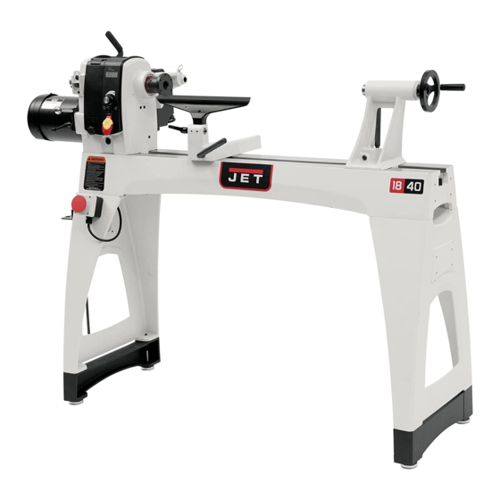
Operating Instructions and Parts Manual
18"x 40" Woodturning Lathe
Models JWL-1840EVS
JET
427 New Sanford Road
LaVergne, Tennessee 37086
Ph.: 800-274-6848
www.jettools.com
Shown with optional JWL1440-TREA
tool rest extension
This .pdf document is bookmarked
Part No. M-719600
Edition 4 12/2018
ECR 181010091219
Copyright © 2017 JET
Advertisement
Table of Contents

Related Manuals for Jet JWL1440-TREA


Summary of Contents for Jet JWL1440-TREA
- Page 1 This .pdf document is bookmarked Operating Instructions and Parts Manual 18”x 40” Woodturning Lathe Models JWL-1840EVS Shown with optional JWL1440-TREA tool rest extension 427 New Sanford Road Part No. M-719600 LaVergne, Tennessee 37086 Edition 4 12/2018 Ph.: 800-274-6848 ECR 181010091219 www.jettools.com...
-
Page 2: Important Safety Instructions
Do not use this lathe for other than its intended 22. Check the condition of the stock to be turned. use. If used for other purposes, JET disclaims Make sure it is free of knots, warpage, checked ends, improperly made or cured glue... -
Page 3: About This Manual
Additional knowledge may be obtained from experienced users or trade articles. Whatever accepted methods are used, always make personal safety a priority. If there are questions or comments, please contact your local supplier or JET. JET can also be reached at our web site: www.jettools.com. -
Page 4: Table Of Contents
3.0 Table of contents Section Page 1.0 IMPORTANT SAFETY INSTRUCTIONS ....................... 2 2.0 About this manual ............................3 3.0 Table of contents ............................4 4.0 Specifications ..............................5 5.0 Setup and assembly ............................7 5.1 Shipping contents ............................ -
Page 5: Specifications
14.5.1 JWL-1840EVS Guard Assembly (OPTIONAL) – Exploded View ............32 14.5.2 JWL-1840EVS Guard Assembly (OPTIONAL) – Parts List ..............32 14.6.1 JWL-1840EVS Comparator Kit (OPTIONAL)–Exploded View ............32 14.6.2 JWL-1840EVS Comparator Kit (OPTIONAL) – Parts List ..............32 ... - Page 6 L= length; W=width; H=height The specifications in this manual were current at time of publication, but because of our policy of continuous improvement, JET reserves the right to change specifications at any time and without prior notice, without incurring obligations.
-
Page 7: Setup And Assembly
5.0 Setup and assembly Lathe must disconnected from power during assembly. 5.1 Shipping contents Carton contents (see Figure 5-1) Lathe bed with headstock, tool support and tailstock – A Tool rest – B Legs – C Spur center – D Live single bearing center –... -
Page 8: Tool Shelf
5.4.1 Hoist lifting method The guard (part no. 719002) is optional and purchased separately. website Position straps around lathe bed. information. IMPORTANT: Do not place straps around Loosen set screw on outer collar (shown in spindle, near levers, knobs or other parts that Figure 5-4) with 4mm hex key. -
Page 9: Spindle Comparator (Optional Accessory)
The bed extension can be mounted to the upper or Install comparator spur center into guard lower holes of the lathe at tailstock end, and lower bracket, by lifting up on plunger and inserting holes at headstock end. Mounting in upper holes comparator spur center until its point is about increases spindle... -
Page 10: Electrical Connections
6.0 Electrical connections Improper connection of the equipment-grounding conductor can result in a risk of electric shock. Check with a qualified Electrical connections must electrician or service person if you are in doubt made qualified electrician as to whether the outlet is properly grounded. Do not modify the plug provided with the tool –... -
Page 11: Adjustments
7.0 Adjustments of bed, and the tailstock moved to accommodate the workpiece. 7.1 Headstock movement 7.4 Cam tightness Push handle (A, Figure 7-1) downward to unlock. The clamping mechanisms of headstock, tailstock Headstock will slide freely along length of bed. and tool rest base are pre-set by the manufacturer, Push handle up to lock. -
Page 12: Tool Rest Extension (Optional)
7.6 Tool rest extension (OPTIONAL) See Figure 7-6. The tool rest extension (optional accessory, #JWL1440-TREA, see your dealer to order) mounts to the tool rest base and offers greater reach for the tool rest when turning off the bed, when the headstock is at the opposite end. See Figure 7-6. -
Page 13: Live Center: Installing/Removing
7.10 Live center: Installing/removing Live centers are installed into the tailstock quill. See Figure 7-9. Disconnect lathe from power source. Clean tapered end of center and inside of tailstock quill, then push center into quill. Test the insertion by attempting to pull the center out of the quill by hand. -
Page 14: Checking Center Alignment
7.14 Checking center alignment When headstock is returned from outboard position, the alignment between centers should be checked. Lock headstock in normal spindle turning position. Slide tailstock toward headstock until centers almost touch (see Figure 7-12). Lock tailstock in position. Figure 7-13: speed range adjustment Figure 7-12: center alignment View the center points from top and side to... -
Page 15: Ac Inverter
Change speed while lathe front of headstock. If you suspect a problem with spindle is turning to avoid overstressing belt. the inverter or inverter settings, contact JET technical service at 1-800-274-6848. A lightning strike or power surge may cause inverter failure. When lathe is... -
Page 16: Operation
For safety and best performance, keep tools sharp. 9.0 Operation If a tool stops cutting or requires excessive pressure to make a cut, it needs to be sharpened. A number of brand name sharpening jigs and The information which follows is general in nature fixtures are available;... -
Page 17: Stock Selection
Figure 9-2 shows the basic profile shapes in spindle turning. Figure 9-2 9.4 Stock Selection Stock for spindles should be straight grained and free of checks, cracks, knots and other defects. It Figure 9-4 should be cut 1/8" to 1/4" larger than the finished Make sure headstock is locked to lathe bed. -
Page 18: Cutting Techniques
9.5.2 Beads Make a parting cut for what is to be a bead to the desired depth. Place the parting tool on the tool support and move tool forward to make the full bevel of the tool come into contact with the workpiece. -
Page 19: Face Plate And Bowl Turning
9.6.1 Mounting Stock Use of a face plate is the most common method for holding a block of wood for turning bowls and plates: Select stock at least 1/8" to 1/4" larger than each dimension on the finished workpiece. Always select the largest diameter face plate that can be used for the workpiece to be turned. -
Page 20: Bowl Turning Techniques
As there are dozens of chucks to choose from, the Large domed scrapers can also be used to help woodturner should first consider all the different clean up the interior surfaces of bowls. A light types of turning that will be done, and read reports touch with the scraper slightly tilted will eliminate or discuss with other turners who own chucks some of the ridges occasionally left by an... - Page 21 Figure 9-10 Figure 9-11 9.7.2 To Shape Interior of Bowl Develop wall thickness at the rim and maintain Stop lathe and move tailstock away. (You may it as you work deeper into the bowl (Once the want to remove the center from the tailstock to piece is thin toward the bottom, you cannot avoid bumping it with your elbow.) make it thinner at the rim).
-
Page 22: User-Maintenance
3mm hex key required. Figure 9-12 To change out a belt or pulley, carefully proceed as follows. If you are uncertain about attempting a belt or pulley change-out, contact JET technical service or take the headstock to an authorized service center. -
Page 23: Troubleshooting Jwl-1840Evs Lathe
11.0 Troubleshooting JWL-1840EVS Lathe 11.1 Electrical and mechanical Table 2 Symptom Possible Cause Correction * Motor fails to develop Power line overloaded. Correct overload condition. full power. Undersized wires in supply system, or Increase supply wire size. extension cord is too long. Low voltage. -
Page 24: Recommended Lathe Speeds
Number of your machine available when you call will allow us to serve you quickly and accurately. Non-proprietary parts, such as fasteners, can be found at local hardware stores, or may be ordered from JET. Some parts are shown for reference only, and may not be available individually. -
Page 25: Jwl-1840Evs Headstock Assembly - Exploded View
14.1.1 JWL-1840EVS Headstock Assembly – Exploded View... -
Page 26: Jwl-1840Evs Headstock Assembly - Parts List
14.1.2 JWL-1840EVS Headstock Assembly – Parts List Index No. Part No. Description Size 1 ....JWL1642-102 .... Spur Center ............. MT2 ....... 1 2 ....6294736 ....Faceplate ..............3" ........1 3 ....6295796 ....Nylon Insert Socket Set Screw ........ 1/4"-20x3/8" ....10 4 .... - Page 27 Index No. Part No. Description Size 69 ....TS-0209011 ....Socket Head Cap Screw ......... 3/8”-16x1/2” ....1 70 ....JWL1642-183 .... Clamp ......................2 71 ....JWL1640EVS-171 ..Safety Guard Bracket ................... 1 72 ....6644005 ....Plunger ......................1 73 ....
-
Page 28: Jwl-1840Evs Controller Assembly - Exploded View
14.2.1 JWL-1840EVS Controller Assembly – Exploded View 14.2.2 JWL-1840EVS Controller Assembly – Parts List Index No. Part No. Description Size 1 ....JWL1640EVS-201 ..Knob ......................1 2 ....JWL1640EVS-202 ..Access Door (With Magnets) ................ 1 3 ....TS-2248252 ....Socket Head Button Screw ........M8-1.25Px25 ....1 4 .... -
Page 29: Jwl-1840Evs Bed And Stand Assembly - Exploded View
14.3.1 JWL-1840EVS Bed and Stand Assembly – Exploded View... -
Page 30: Jwl-1840Evs Bed And Stand Assembly - Parts List
3 ....JWL1440-203 .... Stud ....................... 2 4 ....6294742E ....Tool Rest ..............14" ......... 1 ....JWL1440-TREA ..Optional Tool Rest Extension Assembly (includes #5, 7, 33, 36) ....1 5 ....JWL1440-205 .... Tool Rest Extension, Optional ............... 1 .... -
Page 31: Jwl-1840Evs Extension Bed Assembly (Optional) - Exploded View
14.4.1 JWL-1840EVS Extension Bed Assembly (OPTIONAL) – Exploded View 14.4.2 JWL-1840EVS Extension Bed Assembly (OPTIONAL) – Parts List Index No. Part No. Description Size ....719401 ...... 20" Extension Bed w/ Post (includes #1 thru 6) ..........1 1 ....JWL1440-301 .... Extension Bed ............20” ......... 1 2 .... - Page 32 14.5.1 JWL-1840EVS Guard Assembly (OPTIONAL) – Exploded View 14.5.2 JWL-1840EVS Guard Assembly (OPTIONAL) – Parts List Index No. Part No. Description Size ....719002 ...... Lathe Guard Assembly (includes #1 thru 3) ............ 1 ....JWL1642-179 .... Guard ......................1 2 ....
- Page 34 JET sells through distributors only. The specifications listed in JET printed materials and on official JET website are given as general information and are not binding. JET reserves the right to effect at any time, without prior notice, those alterations to parts, fittings, and accessory equipment which they may deem necessary for any reason whatsoever.
- Page 36 427 New Sanford Road LaVergne, Tennessee 37086 Phone: 800-274-6848 www.jettools.com...
Need help?
Do you have a question about the JWL1440-TREA and is the answer not in the manual?
Questions and answers