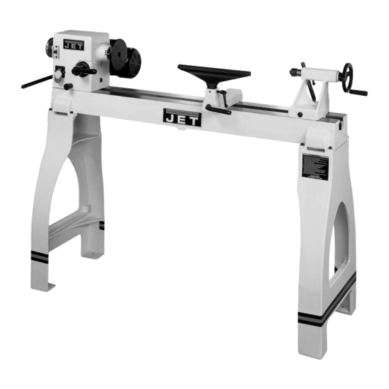
Jet JWL-1442VS Operating Instructions And Parts Manual
Jet tools wood lathe operating instructions and parts manual jwl-1442vs
Hide thumbs
Also See for JWL-1442VS:
- Operating instructions and parts manual (32 pages) ,
- Owner's manual (28 pages)
Table of Contents
Advertisement
Advertisement
Table of Contents

Related Manuals for Jet JWL-1442VS


Summary of Contents for Jet JWL-1442VS
- Page 1 This Manual is Bookmarked Operating Instructions and Parts Manual Wood Lathe Model: JWL-1442VS 708358K Shown WMH Tool Group 2420 Vantage Drive Part Number: M-708358 Elgin, Illinois 60124 Revision C2 1/07 Phone: 800-274-6848 Copyright © WMH Tool Group www.wmhtoolgroup.com...
-
Page 2: Warranty And Service
Warranty and Service WMH Tool Group, Inc., warrants every product it sells. If one of our tools needs service or repair, one of our Authorized Service Centers located throughout the United States can give you quick service. In most cases, any of these WMH Tool Group Authorized Service Centers can authorize warranty repair, assist you in obtaining parts, or perform routine maintenance and major repair on your JET tools. -
Page 3: Warnings
2. This wood lathe is designed and intended for use by properly trained and experienced personnel only. If you are not familiar with the proper and safe operation of a wood lathe, do not use it until the proper training and knowledge have been obtained. - Page 4 30. Provide for adequate space surrounding work area and non-glare, overhead lighting. 31. When stopping the lathe, never grab the part or faceplate to slow it down. Let the work coast to a stop. 32. Use only JET factory authorized replacement parts and accessories; otherwise, the warranty and guarantee are null and void.
-
Page 5: Grounding Instructions
This tool must be grounded while in use to protect the operator from electric shock. In the event of a malfunction or breakdown, grounding provides a path of least resistance for electric current to reduce the risk of electric shock. This tool is equipped with an electric cord having an equipment-grounding conductor and a grounding plug. -
Page 6: 230 Volt Operation
1. Disconnect the machine from the power source. 2. This lathe is supplied with four motor leads that are connected for 115V operation, as shown in Figure A. Reconnect these four motor leads for 230V operation, as shown in Figure B. -
Page 7: Table Of Contents
This manual is provided by JET covering the safe operation and maintenance procedures for a Model JWL-1442VS Wood Lathe. This manual contains instructions on installation, safety precautions, general operating procedures, maintenance instructions and parts breakdown. This machine has been designed and constructed to provide years of trouble free operation if used in accordance to instructions set forth in this manual. -
Page 8: Specifications
Specifications JWL-1442VS Stock Number...708358 Over Bed... 14" Swing Over Tool Rest Base... 10" Distance Between Centers ... 42" Speeds (RPM)...450, 600, 850, 1100, 1500, 1900, 2300, 3000 Spindle Nose... 1" x 8 T.P.I. Drive Spindle Through Hole... 3/8" Tailstock Spindle Through Hole ... 3/8”... -
Page 9: Contents Of The Shipping Container
3. Remove hex cap bolts from skid bottom and lift the lathe bed, with the help from another person, off the skid and into position. 4. Mount the lathe to a solid workbench or refer to the “Stand Legs (optional assembly)” instructions, on page 10, if you have purchased the stand legs. -
Page 10: Stand Legs (Optional Accessory)
Thread a hex nut (C, Fig. 2) onto shaft and leave loose for now. 4. Mount the leg to lathe bed with four 5/16” flat washers and four 5/16”-18 x 1-1/2” hex socket cap screws (D, Fig. 2). - Page 11 Never press the headstock spindle lock while the spindle is turning! H. Headstock On/Off Switch: (H, Fig.5) Flip the switch up to turn “ON” the lathe. Flip the switch down to turn the lathe “OFF”. Headstock On/Off Switch Key: Remove key (I, Fig.
-
Page 12: Tool Rest
N. Tool Rest Body Lock Handle: (N, Fig. 8) Locks the tool rest body in position. Unlock handle to position the tool rest in any location along lathe bed. Tighten handle when properly positioned. O. Tool Rest Lock Handle: (O, Fig. 8) Locks the tool rest in position. -
Page 13: Mounting Workpiece Between Centers
7. Start lathe at lowest speed and bring it up to the appropriate RPM for the size of stock, see Figure 6 page 11. -
Page 14: Stock Selection
Stock Selection Stock for spindles should be straight grained and free of checks, cracks, knots and other defects. It should be cut 1/8" to 1/4" larger than the finished diameter and may require additional length to remove ends if required. Larger stock should have the corners removed to produce an octagon making the piece easier to rough down to a cylinder, see Figure 13. -
Page 15: Beads, Coves, "V" Cuts And Parting
1. Place the parting tool on the tool rest and move the tool forward to make the full bevel of the tool contact the workpiece. Gently raise handle to make cut to the appropriate depth. 2. Repeat for other side of the bead. 3. -
Page 16: Sanding And Finishing
To apply a finish, the workpiece can be left on the lathe. Turn off lathe and use a brush, or cloth to apply the finish. Remove excess finish before restarting lathe. Allow drying and sanding again with 320 or 400 grit sandpaper. -
Page 17: Face Plate Or Chuck
While faceplates are the simplest, most reliable method of holding a block of wood for turning, chucks can also be used. A chuck is not a requirement but is handy when working on more than one piece at a time. Rather than removing screws, you simply open the chuck and change workpieces. -
Page 18: Headstock Taper
5. Turn the workpiece by hand to ensure proper clearance. 6. Start the lathe at the lowest speed and bring it up to the maximum safe speed for the size of work to be turned, see Figure 6 on page 11. -
Page 19: To Shape The Interior Of A Bowl
1. Stop the lathe and move the tailstock away. Remove the center from the tailstock to prevent bumping it with your elbow. 2. Adjust the tool support in front of the bowl just below the centerline, at a right angle to the lathe bed. -
Page 20: Adjusting The Clamping Mechanism
The clamps are pre-set at the factory and should need adjustment. adjustment is needed, remove the stud (A, Fig. 23). Loosen the locking handle and slide the headstock, tailstock or tool rest to the edge of the bed and slightly turn the hex nut (B, Fig. 23). Slide back into position and test the handle to make sure it securely locks. -
Page 21: Troubleshooting
RPM, or scrap workpiece all together 2. Replace bearings 3. Replace belt 4. Tighten bolts 5. Shim lathe bed, or adjust feet on stand 1. Reduce cut depth 2. Replace motor 3. Replace belt 4. Replace bearings 5. -
Page 22: Bed Assembly
Bed Assembly... - Page 23 Bed Assembly Index Part Description Size Qty. 1... JWL1442-201 ...Bed ..1 2... JWL1442-202 ...Stud ..3 3... JWL1442-124 ...C-Ring... S19... 3 4... 6295703...Hex Socket Cap Screw... 10-24 x 5/8”... 4 5... JWL1442-205 ...Tool Rest..1 6... JWL1442-206 ...Tool Support Handle..1 7...
-
Page 24: Headstock Assembly
Headstock Assembly... - Page 25 Headstock Assembly Index Part Description Size Qty. 1... JWL1442-101 ...Spur Center... MT2 ... 1 2... JWL1442-102 ...Face Plate... 6” ... 1 3... JWL1442-103 ...Spindle..1 4... JWL1442-104 ...Key... 4 x 4 x 80 ... 1 5... JWL1442-105 ...E-Ring... E-19... 1 6...
- Page 26 Headstock Assembly (continued) Index Part Description Size Qty. 43... BB-6006LLB ...Ball Bearing... 6006LLB ... 1 44... JWL1442-144 ...C-Ring... S32... 1 45... JWL1442-145 ...Shifting Lever Bracket..1 46... JWL1442-146 ...Rack..1 47... JWL1442-147 ...Strain Relief Bushing ..2 48...
-
Page 27: Stand Assembly
Stand Assembly (optional accessory) Stand Assembly Index Part Description Size Qty. 3... JWL1642-203 ...Stand ..2 5... JWL1642-205 ...JET Stripe ..1 6... JWL1642-206 ...Adjustable Foot ... 3/8” ... 4 7... TS-0561031 ...Hex Nut ... 3/8” ... 4 9... -
Page 28: Safety Guard
1. Mount the guard bracket (A) to the headstock with two 3/8” flat washers, two 3/8” lock washers and two 3/8”-16 x 1-1/2” socket head cap screws (B). 2. Attach the guard (C) to the guard bracket by inserting the rod and lifting up on the plunger (D). 3. - Page 29 Safety Guard Assembly Safety Guard Assembly Index Part Description Size Qty. 1... JWL1442-301 ...Guard Bracket ..1 2... TS-0270011 ...Set Screw... 5/16”-18x1/4” ... 2 3... JWL1642-187 ...Collar ..2 4... TS-0680041 ...Flat Washer... 3/8” ... 2 5... TS-0720091 ...Lock Washer ... 3/8” ... 2 6...
-
Page 30: Parts Breakdown
Tool Basket 1. Mount the bracket (A, Fig. 1) to the inside of the lathe leg with two 5/16”-18 x 1-1/2” Hex Socket Cap Screws, four 5/16” flat washers and two 5/16” hex nuts (B, Fig. 1). 2. The two setscrews, on the bracket should be... -
Page 31: Wiring Diagram
Wiring Diagram... -
Page 32: Indexer Positions
How to use the chart A diagram of the indexer is shown at right, as viewed from the tailstock end of the Lathe. Points A, B and C are the holes in the head casting. The holes in the spindle collar may be considered as numbered 1 through 12.
Need help?
Do you have a question about the JWL-1442VS and is the answer not in the manual?
Questions and answers
is thepulley belt tightest when set at high speed or low speed onjet 1442
The pulley belt is tightest when set at high speed on the Jet JWL-1442VS.
This answer is automatically generated
@Mr. Anderson thank you mine is the opposite must need altered somehow