Jet JWL-1440VS Operating Instructions And Parts Manual
14”x 40” woodturning lathe
Hide thumbs
Also See for JWL-1440VS:
- Operating instructions manual (49 pages) ,
- Operating instructions and parts manual (32 pages)
Table of Contents
Advertisement
This .pdf document is bookmarked
Operating Instructions and Parts Manual
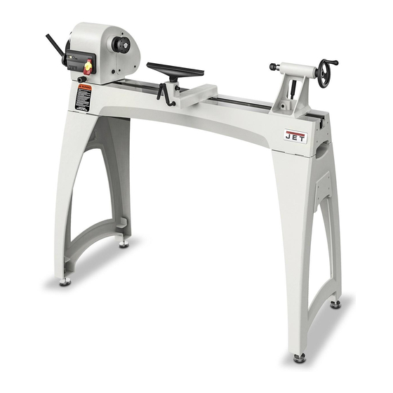
14"x 40" Woodturning Lathe
Model JWL-1440VS
Shown with optional 20-inch extension bed (#719401)
JET
427 New Sanford Road
LaVergne, Tennessee 37086
Part No. M-719400
Ph.: 800-274-6848
Revision C 11/2014
www.jettools.com
Copyright © 2014 JET
Advertisement
Table of Contents

Related Manuals for Jet JWL-1440VS


Summary of Contents for Jet JWL-1440VS
- Page 1 This .pdf document is bookmarked Operating Instructions and Parts Manual 14”x 40” Woodturning Lathe Model JWL-1440VS Shown with optional 20-inch extension bed (#719401) 427 New Sanford Road LaVergne, Tennessee 37086 Part No. M-719400 Ph.: 800-274-6848 Revision C 11/2014 www.jettools.com Copyright © 2014 JET...
-
Page 2: Warranty And Service
JET sells through distributors only. The specifications listed in JET printed materials and on official JET website are given as general information and are not binding. JET reserves the right to effect at any time, without prior notice, those alterations to parts, fittings, and accessory equipment which they may deem necessary for any reason ®... -
Page 3: Table Of Contents
16.3.1 JWL-1440VS Leg Set – Exploded View ....................30 16.3.2 JWL-1440VS Leg Set – Parts List ....................... 30 16.4.1 JWL-1440VS Extension Bed Assembly (OPTIONAL) – Exploded View ..........31 16.4.2 JWL-1440VS Extension Bed Assembly (OPTIONAL) – Parts List ............31 ... -
Page 4: Safety Warnings
with all of these warnings may cause serious injury. 17. Some dust created by power sanding, sawing, grinding, drilling other construction 3.0 Safety warnings activities contain chemicals known to cause cancer, birth defects or other reproductive harm. Some examples of these chemicals are: 1. -
Page 5: About This Manual
Additional knowledge may be obtained from experienced users or trade articles. Whatever accepted methods are used, always make personal safety a priority. If there are questions or comments, please contact your local supplier or JET. JET can also be reached at our web site: www.jettools.com. -
Page 6: Specifications
5.0 Specifications Model number ............................JWL-1440VS Stock numbers: Lathe with Leg Set ..........................719400K Lathe only ..............................719400 Leg Set only ............................. 719402 Bed Extension 20”, with tool post (optional accessory) ................719401 Motor and electricals: Motor type ................totally enclosed fan cooled, induction, capacitor start Horsepower .......................... -
Page 7: Jwl-1440Vs Hole Pattern
Optional Bed Extension only ..............49.5 lb (22.5 kg) ....56 lb (25 kg) The specifications in this manual were current at time of publication, but because of our policy of continuous improvement, JET reserves the right to change specifications at any time and without prior notice, without incurring obligations. -
Page 8: Setup And Assembly
6.2 Unpacking and cleanup 6.0 Setup and assembly 1. Remove all smaller items from main carton. Do not discard carton or packing material until 6.1 Shipping contents lathe is assembled and running satisfactorily. Carton contents for # 719400K (see Figure 2) 2. -
Page 9: Mounting Bed Extension (Optional Accessory)
8mm hex key required. The 20” bed extension (p/n 719401) is optional and purchased separately. See your JET dealer for information. If you did not purchase the bed extension, proceed to section 6.6. The bed extension can be mounted to the upper or lower holes of the lathe. -
Page 10: Electrical Connections
8. An adapter, shown in B and C, may be used to injury. connect this plug to a 2-pole receptacle as shown The JWL-1440VS Lathe is rated at 115/230V in B if a properly grounded outlet is not available. power, and is pre-wired for 115 volt. The lathe... -
Page 11: Extension Cords
Alternatively, the lathe may be “hard-wired” to 4. Release knob (B) and it will seat itself with an the power source. If you are hard-wiring the audible click when the headstock reaches a lathe to a panel, make sure a disconnect is positive lock position. -
Page 12: Cam Tightness
A 12-inch tool rest is provided with your lathe. It is The JWL-1440VS lathe provides 36 indexing designed to allow adjustment for height, position on positions. These are identified in the chart in the bed, and angle to the work. -
Page 13: Spur Center: Installing/Removing
3. Perform the desired procedure. sure the keyway (N, Figure 16) in the quill is aligned with the locking handle. 4. Unscrew the index pin until the spindle is released. Rotate spindle to next desired hole, To remove the live center: and repeat. -
Page 14: Checking Center Alignment
“play” in the headstock to adjust for this alignment. Lock the headstock when finished. Figure 20 The JWL-1440VS contains a Reeves or “split- pulley” system. As speed is increased, via the speed change handle, the spindle pulley widens and the belt drops down to the smaller diameter between the pulley halves. -
Page 15: Turning Tools
4. Bed ways; keep clean, use steel wool to remove any rust spots, and apply paste wax to prevent buildup of rust and finishes. 5. Tool rest; use a mill file to remove nicks and dings. 6. Spindle tapers; should be clean and free of dust and chips for proper seating of tapers. -
Page 16: Stock Selection
10.4 Stock Selection Never use a steel face Stock for spindles should be straight grained and hammer and never drive the workpiece free of checks, cracks, knots and other defects. It onto the spur center while it is mounted in should be cut 1/8"... -
Page 17: Cutting Techniques
10.5 Cutting Techniques 10.5.3 Coves 10.5.1 Roughing Out 1. Use a spindle gouge. With the flute of the tool at 90 degrees to the workpiece, touch the point 1. Begin with a large roughing gouge. Place the of the tool to the workpiece and roll in towards tool on the tool rest with the heel of the tool on the bottom of the cove. -
Page 18: Face Plate And Bowl Turning
6. Additional cuts may be taken to add to either metal screws are case hardened with deeper the depth or width of the cut. and sharper threads than wood screws.) 10.5.5 Parting Off If the mounting screws on the face plate interfere with the workpiece, a glue or waste block can be used: 1. -
Page 19: Bowl Turning Techniques
10.6.3 Wood Selection from what appears to be the center of the top of the workpiece. Firewood is the cheapest, most widely available 2. Drive spur center into the top of the workpiece stock to use while learning to turn bowls. Simply with a mallet or dead blow hammer. - Page 20 10.7.2 To Shape Interior of Bowl 9. Begin the separation with a parting tool, but do not cut all the way through yet. 1. Stop lathe and move tailstock away. (You may 10.7.3 Sanding and Finishing want to remove the center from the tailstock to avoid bumping it with your elbow.) 1.
-
Page 21: Maintenance
12.0 Optional accessory This accessory item, purchased separately, can enhance the functionality of your lathe. Contact your dealer to order, or call JET at the phone number on the cover. 719401 ..20" Extension Bed w/ Post... -
Page 22: Troubleshooting The Jwl-1440Vs Lathe
13.0 Troubleshooting the JWL-1440VS Lathe Table 3 Symptom Possible Cause Correction Motor fails to develop Power line overloaded. Correct overload condition. full power. Undersized wires in supply system, or Increase supply wire size. extension cord is too long. Running capacitor is bad. -
Page 23: Recommended Lathe Speeds (Per Diameter Of Workpiece)
14.0 Recommended Lathe Speeds (per diameter of workpiece) Diameter of Work Roughing RPM General Cutting RPM Finishing RPM Under 2” 1520 3000 3000 2” to 4” 1600 2290 4” to 6” 1080 1500 6” to 8” 1125 8” to 10” 10”... -
Page 24: Indexer Positions
15.0 Indexer Positions How to use the chart A diagram of the indexer is shown at right, as viewed from the tailstock end of the Lathe. Points A, B and C are the holes in the head casting. The holes in the spindle collar may be considered as numbered 1 through 12. -
Page 25: Replacement Parts
800-274-6848 Monday through Friday, 8:00 a.m. to 5:00 p.m. CST. Having the Model Number and Serial Number of your machine available when you call will allow us to serve you quickly and accurately. 16.1.1 JWL-1440VS Headstock Assembly – Exploded View... -
Page 26: Jwl-1440Vs Headstock Assembly - Parts List
16.1.2 JWL-1440VS Headstock Assembly – Parts List Index No. Part No. Description Size 1 ....JML-3 ......Spur Center ............. MT2 ......1 1A ....JML-3A ...... Center Point for Spur Center ................. 1 2 ....JWL1440-102 .... Faceplate ..............3" ........1 3 .... - Page 27 Index No. Part No. Description Size 61 ....JWL1440-161 .... Motor (includes #62) ..................1 ....JWL1440-MF..... Motor Fan (not shown)................... 1 ....JWL1440-MFC ..Motor Fan Cover (not shown) ................ 1 ....JWL1440-CS ..... Centrifugal Switch (not shown) ..............1 ....
-
Page 28: Jwl-1440Vs Bed Assembly - Exploded View
16.2.1 JWL-1440VS Bed Assembly – Exploded View... -
Page 29: Jwl-1440Vs Bed Assembly - Parts List
16.2.2 JWL-1440VS Bed Assembly – Parts List Index No. Part No. Description Size 1 ....JET-113..... JET Nameplate ....................1 2 ....JWL1440-202 .... Bed ........................ 1 3 ....JWL1440-203 .... Stud ....................... 2 4 ....JWL1442-205 .... Tool Rest ..............12" ......... 1 5 .... -
Page 30: Jwl-1440Vs Leg Set - Exploded View
Index No. Part No. Description Size ....719402 ...... JWL-1440VS Leg Set (includes #1 thru 6) ............ 1 1 ....JWL1440-401 .... Leg ......................... 2 2 ....TS-0208071 ....Socket Head Cap Screw.......... 5/16”-18x1-1/4” ..... 8 3 ....TS-0720081 ....Lock Washer ............5/16” ......8 4 .... -
Page 31: Jwl-1440Vs Extension Bed Assembly (Optional) - Exploded View
16.4.1 JWL-1440VS Extension Bed Assembly (OPTIONAL) – Exploded View 16.4.2 JWL-1440VS Extension Bed Assembly (OPTIONAL) – Parts List Index No. Part No. Description Size ....719401 ...... 20" Extension Bed w/ Post (includes #1 thru 6) ..........1 1 ....JWL1440-301 .... Extension Bed............20” ......... 1 2 .... -
Page 32: Electrical Connections
17.0 Electrical Connections...
Need help?
Do you have a question about the JWL-1440VS and is the answer not in the manual?
Questions and answers
Total weight
The total weight of the Jet JWL-1440VS, when assembled with the lathe and leg set, is 220 lb (100 kg) + 132 lb (60 kg) = 352 lb (160 kg).
This answer is automatically generated
My JWL1440 is 2 band variable speed with readout can’t find reference to this lathe looking for parts manual.
The manual for the Jet JWL-1440VS lathe includes a parts breakdown. You should retain the manual for future reference. If you do not have it, you may contact your local supplier or JET for assistance.
This answer is automatically generated