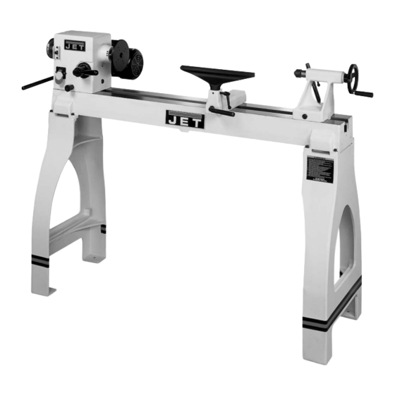
Jet JWL-1442VS Owner's Manual
Wood lathe
Hide thumbs
Also See for JWL-1442VS:
- Operating instructions and parts manual (32 pages) ,
- Operating instructions and parts manual (32 pages)
Table of Contents
Advertisement
Advertisement
Table of Contents

Related Manuals for Jet JWL-1442VS


Summary of Contents for Jet JWL-1442VS
- Page 1 OWNER'S MANUAL JWL-1442VS Wood Lathe 708358K Shown WMH TOOL GROUP Consumer/Light Industrial Products Division P.O. BOX 1349 Auburn, WA 98071-1349 Ph: 1-800-274-6848 Fax: 1-800-274-6840 E-mail: jet@wmhtoolgroup.com www.wmhtoolgroup.com M-708358 09/02 Copyright © WMH Tool Group...
-
Page 2: Warranty
This manual has been prepared for the owner and operators of a JWL-1442VS. Its purpose, aside from machine operation, is to promote safety through the use of accepted correct operating and maintenance procedures. Completely read the safety and maintenance instructions before operating or servicing the machine. -
Page 3: Warnings
WARNING 1. Read and understand the entire owner’s manual before attempting assembly or operation. 2. This wood lathe is designed and intended for use by properly trained and experienced personnel only. If you are not familiar with the proper and safe operation of a wood lathe, do not use until proper training and knowledge have been obtained. - Page 4 35. Do not use this JET wood lathe for other than its intended use. If used for other purposes, JET disclaims any real or implied warranty and holds itself harmless from any injury that may result from...
-
Page 5: Grounding Instructions
Grounding Instructions Caution: This tool must be grounded while in use to protect the operator from electric shock. In the event of a malfunction or breakdown, grounding provides a path of least resistance for electric current to reduce the risk of electric shock. This tool is equipped with an electric cord having an equipment-grounding conductor and a grounding plug. -
Page 6: 230V Operation
3. The 115V attachment plug (A), supplied with the lathe, must be replaced with a UL/CSA listed plug suitable for 230V operation (D). Contact your local Authorized JET Service Center or qualified electrician for proper procedures to install the plug. The lathe must comply with all local and national codes after the 230 volt plug is installed. -
Page 7: Table Of Contents
Introduction The JET JWL-1442VS lathe you have purchased is a high quality tool that will give you years of superior service. You will get maximum performance and enjoyment from your new lathe if you would take a few moments now to review the entire manual before beginning assembly and operation. -
Page 8: Specifications
Specifications JWL-1442VS Stock Number..........................708358 Over Bed ..............................14" Swing Over Tool Rest Base ........................10" Distance Between Centers........................42" Speeds (RPM) ..............450, 600, 850, 1100, 1500, 1900, 2300, 3000 Spindle Nose ...........................1" x 8 T.P.I. Drive Spindle Through Hole .........................3/8" Tailstock Spindle Through Hole......................3/8”... -
Page 9: Contents Of The Shipping Container
WARNING Read and understand the entire contents of this manual before attempting assembly or operation! Failure to comply may cause serious injury! Contents of the Shipping Containers 1. Lathe 1. Tailstock 1. Headstock 1. Face Plate 1. Tool Rest Body 1. -
Page 10: Stand Legs (Optional Accessory)
Stand Legs (optional accessory) 1. At this point the headstock, tailstock and tool rest should be removed. With help from another person lift the lathe bed and place onto a workbench. 2. Angle lathe bed so that stand leg mounting holes are accessible, see Figure 2. - Page 11 G. Headstock Spindle Lock: (G, Fig. 5) Push in pin to keep the spindle from turning. CAUTION! Never press the headstock spindle lock while the spindle is turning! H. Headstock On/Off Switch: (H, Fig.5) Flip the switch up to turn “ON” the lathe. Flip the switch down to turn the lathe “OFF”.
-
Page 12: Lathe Tools
The following tools provide the basics for most woodturning projects. See your JET distributor for a wide variety of JET woodturning tools. Roughing Gouge - used for rapidly cut raw wood into round stock, see Figure 10. -
Page 13: Mounting Workpiece Between Centers
Lathe Tools (continued) 5. Move tool rest into position. It should be parallel to workpiece, approximately at the Skew - used to make vees, beads, etc., see centerline, and approximately 1/8" from the Figure 11. closest part of the workpiece. Lock tool rest body and tool rest in place. -
Page 14: Stock Selection
Stock Selection Stock for spindles should be straight grained and free of checks, cracks, knots and other defects. It should be cut 1/8" to 1/4" larger than the finished diameter and may require additional length to remove ends if required. Larger stock should have the corners removed to produce an octagon making the piece easier to rough down to a cylinder, see Figure 13. -
Page 15: Beads, Coves, "V" Cuts And Parting
Beads Parting 1. Place parting tool on the tool rest and move 1. Place parting tool on tool rest and raise the tool forward to make the full bevel of the tool handle until it starts to cut and continue to come in contact with the workpiece. -
Page 16: Sanding & Finishing
Sanding & Finishing Leaving clean cuts will reduce the amount of sanding required. Begin with a fine sandpaper (120 grit or finer). Coarser sandpaper will leave deep scratches that are difficult to remove, and dull crisp details. Fold the sandpaper into a pad;... -
Page 17: Face Plate Or Chuck
Face Plate or Chuck gouges. It also allows removal of wood much faster and with less vibration than other gouges. While faceplates are the simplest, most reliable Most average sized bowl work method of holding a block of wood for turning, accomplished with a 3/8"... -
Page 18: To Shape Outside Of Bowl
1/4" from the workpiece. Note: For larger outboard turning, an optional outboard turning stand is used to place the tool support, see your JET distributor. 5. Turn workpiece by hand to ensure proper clearance. 6. Start lathe at lowest speed and bring it up to the maximum safe speed for the size of work to be turned, see Figure 6 on page 11. -
Page 19: To Shape Interior Of Bowl
To Shape Interior of Bowl Coarser sandpaper tends to leave deep scratches that are hard to eliminate. Use 1. Stop lathe and move tailstock away. power-sanding techniques avoid Remove center from tailstock to prevent concentric sanding marks around your bumping it with elbow. finished piece. -
Page 20: Adjusting Clamping Mechanism
Slide back into position and test the handle to make sure it securely locks. Changing the Belt and Bearings Changing belt and bearings can be a difficult task, and should be performed by a JET authorized repair station. Remove headstock and take into a repair station for servicing. -
Page 21: Troubleshooting
Troubleshooting Problem Possible Cause Solution 1. Workpiece warped, out of 1. Correct problem by planing, round, has major flaw, bandsawing, reduce the improperly prepared for RPM, or scrap workpiece all turning, or RPM is set too together high 2. Replace bearings Excessive Vibration. -
Page 22: Part Breakdowns And Part's List
Bed Assembly... - Page 23 Parts List for the JWL-1442VS Woodworking Lathe Bed Assembly Index Part Description Size Qty. 1..JWL1442-201....Bed....................... 1 2..JWL1442-202....Stud...................... 3 3..JWL1442-124....C-Ring ...........S19 ......... 4 4..TS-0206031 ....Hex Socket Cap Screw ......10-24 x 5/8”......4 5..JWL1442-205....Tool Rest ....................1 6..JWL1442-206....
- Page 24 Headstock Assembly...
- Page 25 Headstock Assembly Index Part Description Size Qty. 1..JWL1442-101....Spur Center ...........MT2 ........1 2..JWL1442-102....Face Plate ..........6” ..........1 3..JWL1442-103....Spindle ....................1 4..JWL1442-104....Key............4 x 4 x 80 ........ 1 5..JWL1442-105....E-Ring ...........E-19 ........1 6..BB-6205ZZ....Ball Bearing ...........6205ZZ ........1 7..JWL1442-107....
- Page 26 52 ..TS-0720081 ....Lock Washer..........5/16” ........2 53 ..JWL1442-153....Plate..................... 1 54 ..JWL1442-154....Clamp....................1 55 ..JWL1442-155....JET Label ..................... 1 56 ..JWL1442-156....Warning Label ..................1 57 ..JWL1442-157....Speed Label ..................1 58 ..JWL1442-158....Motor Label ..................1 59 ..JWL1442-159....
- Page 27 Description Size Qty. 3..JWL1642-203....Stand....................2 5..JWL1642-205....JET Stripe..................... 1 6..JWL1642-206....Adjustable Foot........3/8” ......... 4 7..TS-0561031 ....Hex Nut ..........3/8” ......... 4 9..TS-0208081 ....Hex Socket Cap Screw ......5/16”-18 x 1-1/2”...... 8 10 ..TS-0680032 ....Flat Washer ...........5/16” ........8...
-
Page 28: Wiring Diagram
Wiring Diagram...
Need help?
Do you have a question about the JWL-1442VS and is the answer not in the manual?
Questions and answers