Jet JWL-1840EVS Operating Instructions And Parts Manual
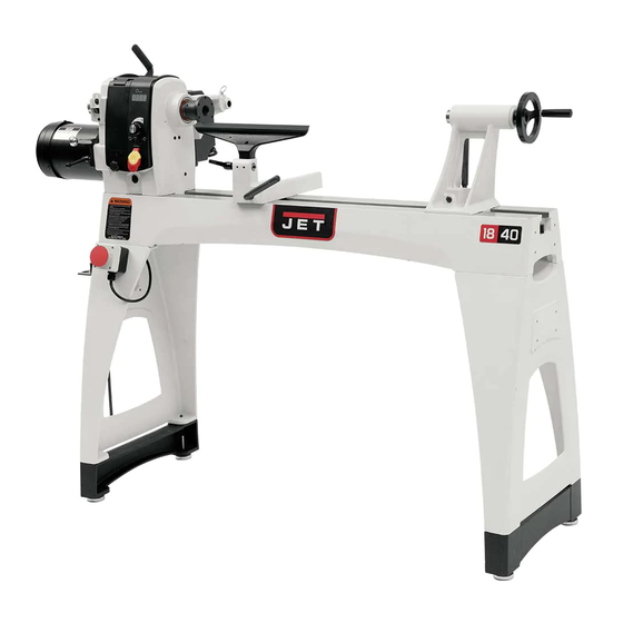
18”x 40” woodturning lathe
Hide thumbs
Also See for JWL-1840EVS:
- Operating instructions manual (51 pages) ,
- Operating instructions and parts manual (44 pages) ,
- Operating instructions and parts manual (37 pages)
Table of Contents
Advertisement
Quick Links
Advertisement
Table of Contents

Related Manuals for Jet JWL-1840EVS


Summary of Contents for Jet JWL-1840EVS
- Page 1 This .pdf document is bookmarked Operating Instructions and Parts Manual 18”x 40” Woodturning Lathe Model JWL-1840EVS 427 New Sanford Road LaVergne, Tennessee 37086 Part No. M-719600 Ph.: 800-274-6848 Edition 1 06/2016 www.jettools.com Copyright © 2016 JET...
-
Page 2: Important Safety Instructions
Lead from lead based paint. • 5. Do not use this lathe for other than its intended Crystalline silica from bricks, cement and use. If used for other purposes, JET disclaims other masonry products. any real or implied warranty and holds itself •... -
Page 3: About This Manual
Additional knowledge may be obtained from experienced users or trade articles. Whatever accepted methods are used, always make personal safety a priority. If there are questions or comments, please contact your local supplier or JET. JET can also be reached at our web site: www.jettools.com. -
Page 4: Table Of Contents
14.2.1 JWL-1840EVS Controller Assembly – Exploded View ................ 28 14.2.2 JWL-1840EVS Controller Assembly – Parts List ................. 28 14.3.1 JWL-1840EVS Bed and Stand Assembly – Exploded View ..............29 14.3.2 JWL-1840EVS Bed and Stand Assembly – Parts List ................ 30 ... -
Page 5: Specifications
14.5.2 JWL-1840EVS Guard Assembly (OPTIONAL) – Parts List ..............32 14.6.1 JWL-1840EVS Comparator Kit (OPTIONAL)–Exploded View ............32 14.6.2 JWL-1840EVS Comparator Kit (OPTIONAL) – Parts List ..............32 15.0 Electrical Connections for JWL-1840EVS ....................33 ... - Page 6 L= length; W=width; H=height The specifications in this manual were current at time of publication, but because of our policy of continuous improvement, JET reserves the right to change specifications at any time and without prior notice, without incurring obligations.
-
Page 7: Setup And Assembly
5.0 Setup and assembly Lathe must disconnected from power during assembly. 5.1 Shipping contents Carton contents (see Figure 5-1) Lathe bed with headstock, tool support and tailstock – A Tool rest – B Legs – C Spur center – D Live single bearing center –... -
Page 8: Tool Shelf
5.4.1 Hoist lifting method The guard (part no. 719002) is optional and purchased separately. website information. 1. Position straps around lathe bed. IMPORTANT: Do not place straps around 1. Loosen set screw on outer collar (shown in spindle, near levers, knobs or other parts that Figure 5-4) with 4mm hex key. -
Page 9: Spindle Comparator (Optional Accessory)
The spindle comparator consists of two centers inserted into the brackets at rear of lathe. The The JWL-1840EVS lathe requires 230-volt single- comparator is used to mount a finished, or phase input. It is equipped with a power inverter, “reference”... -
Page 10: Grounding Instructions
Table 1 6.2 230V operation As received from the factory, the JWL-1840EVS is ready to run at 230-volt operation. This tool is intended for use on a circuit that has an outlet that looks like the one illustrated in A, Figure 6-1. -
Page 11: Adjustments
6. Rotate knob (B) clockwise until it engages the 7.0 Adjustments threads. 7.1 Headstock movement Always engage locking handle (A) before operating lathe. 7.1.1 Sliding 7.2 Tailstock movement Push handle (A, Figure 7-1) downward to unlock. Headstock will slide freely along length of bed. To slide tailstock, push locking handle (C, Figure 7- Push handle up to lock. -
Page 12: Tool Rest
Tighten locking handle firmly before operating lathe. The JWL-1840EVS lathe provides 36 indexing positions at 10-degree increments. Loosen handle (H) to raise or lower tool rest and angle it to the work. Tighten handle before 1. -
Page 13: Spur Center: Installing/Removing
To remove a live center: 4. Back off tailstock and remove workpiece from lathe. 5. Loosen quill lock handle (M). 6. Rotate handwheel counterclockwise to retract quill all the way, until live center comes out. Hold the center while doing this to prevent it from falling. -
Page 14: Face Plate: Installing/Removing
4. If centers do not align, unlock headstock and pivot it slightly. There should be enough “play” in headstock to adjust for this alignment. Lock headstock when finished. 7.15 Speed Change (EVS model only) See Figure 7-13. 1. Disconnect lathe from power source. 2. -
Page 15: Operating Controls
ADJUST INVERTER SETTINGS. Use only the controls on front of headstock. If you suspect a problem with the inverter or inverter settings, contact JET technical service at 1-800-274-6848. A lightning strike or power surge may cause inverter failure. When lathe is... -
Page 16: Operation
For safety and best performance, keep tools sharp. 9.0 Operation If a tool stops cutting or requires excessive pressure to make a cut, it needs to be sharpened. The information which follows is general in nature A number of brand name sharpening jigs and and not intended to be a complete course in fixtures are available;... -
Page 17: Stock Selection
Figure 9-2 shows the basic profile shapes in spindle turning. Figure 9-2 9.4 Stock Selection Stock for spindles should be straight grained and Figure 9-4 free of checks, cracks, knots and other defects. It should be cut 1/8" to 1/4" larger than the finished 4. -
Page 18: Cutting Techniques
9.5.2 Beads 1. Make a parting cut for what is to be a bead to the desired depth. Place the parting tool on the tool support and move tool forward to make the full bevel of the tool come into contact with the workpiece. -
Page 19: Face Plate And Bowl Turning
9.6.1 Mounting Stock Use of a face plate is the most common method for holding a block of wood for turning bowls and plates: 1. Select stock at least 1/8" to 1/4" larger than each dimension on the finished workpiece. 2. -
Page 20: Bowl Turning Techniques
9.6.2 Faceplate or Chuck? other gouges. Most average sized bowl work can be accomplished with a 3/8" or 1/2" bowl gouge. While faceplates are the simplest, most reliable A 1/4" bowl gouge is best suited for smaller bowls method of holding a block of wood for turning, and light finishing cuts. - Page 21 10. Finish turning the outside of bowl with 1/2" or 3/8" bowl gouge. Leave additional material at base of bowl for support while turning interior. This will be removed later. Figure 9-11 7. Develop wall thickness at the rim and maintain it as you work deeper into the bowl (Once the piece is thin toward the bottom, you cannot Figure 9-10...
-
Page 22: User-Maintenance
3mm hex key required. Figure 9-12 To change out a belt or pulley, carefully proceed as follows. If you are uncertain about attempting a belt or pulley change-out, contact JET technical service or take the headstock to an authorized service center. -
Page 23: Troubleshooting Jwl-1840Evs Lathe
11.0 Troubleshooting JWL-1840EVS Lathe Table 2 Symptom Possible Cause Correction * Motor fails to develop Power line overloaded. Correct overload condition. full power. Undersized wires in supply system, or Increase supply wire size. extension cord is too long. Low voltage. -
Page 24: Recommended Lathe Speeds
Table 3 13.0 Optional accessories These accessory items, purchased separately, can enhance the functionality of your lathe. Contact your dealer to order, or call JET at the phone number on the cover. 719001 ..Tailstock Swing Away 719002 ..Guard 719401 .. -
Page 25: Replacement Parts
Number of your machine available when you call will allow us to serve you quickly and accurately. Non-proprietary parts, such as fasteners, can be found at local hardware stores, or may be ordered from JET. Some parts are shown for reference only, and may not be available individually. -
Page 26: Jwl-1840Evs Headstock Assembly - Parts List
14.1.2 JWL-1840EVS Headstock Assembly – Parts List Index No. Part No. Description Size 1 ....JWL1642-102 .... Spur Center ............. MT2 ....... 1 2 ....6294736 ....Faceplate ..............3" ........1 3 ....6295796 ....Nylon Insert Socket Set Screw ........ 1/4"-20x3/8" ....10 4 .... - Page 27 Index No. Part No. Description Size 62 ....JWL1840EVS-162..Inverter..............VFD015E21A ....1 63 ....JWL1640EVS-163..Inverter Lower Box..................1 64 ....TS-0560071 ....Hex Nut ..............#10-24 ......7 65 ....JWL1642-169 .... Braking Resistor ................... 1 66 ....
-
Page 28: Jwl-1840Evs Controller Assembly - Exploded View
14.2.1 JWL-1840EVS Controller Assembly – Exploded View 14.2.2 JWL-1840EVS Controller Assembly – Parts List Index No. Part No. Description Size 1 ....JWL1640EVS-201..Knob ......................1 2 ....JWL1640EVS-202..Access Door (With Magnets) ................ 1 3 ....TS-2248252 ....Socket Head Button Screw ........M8-1.25Px25 ....1 4 .... -
Page 29: Jwl-1840Evs Bed And Stand Assembly - Exploded View
14.3.1 JWL-1840EVS Bed and Stand Assembly – Exploded View... -
Page 30: Jwl-1840Evs Bed And Stand Assembly - Parts List
29 ....JWL1440-229 .... C-Ring..............S-12 ......1 30 ....JWL1440-230 .... Bolt......................... 1 31 ....LM000214 ....ID Label, JWL-1840EVS ................1 32 ....JWL1221VS-211 ..Warning Label....................1 33 ....TS-0570031 ....Hex Nut ..............3/8” ........ 2 34 .... -
Page 31: Jwl-1840Evs Extension Bed Assembly (Optional) - Exploded View
14.4.1 JWL-1840EVS Extension Bed Assembly (OPTIONAL) – Exploded View 14.4.2 JWL-1840EVS Extension Bed Assembly (OPTIONAL) – Parts List Index No. Part No. Description Size ....719401 ...... 20" Extension Bed w/ Post (includes #1 thru 6) ..........1 1 ....JWL1440-301 .... Extension Bed............20” ......... 1 2 .... -
Page 32: Jwl-1840Evs Guard Assembly (Optional) - Exploded View
14.5.1 JWL-1840EVS Guard Assembly (OPTIONAL) – Exploded View 14.5.2 JWL-1840EVS Guard Assembly (OPTIONAL) – Parts List Index No. Part No. Description Size ....719002 ...... Lathe Guard Assembly (includes #1 thru 3) ............ 1 ....JWL1642-179 .... Guard ......................1 2 .... - Page 33 15.0 Electrical Connections for JWL-1840EVS...
-
Page 34: Warranty And Service
JET sells through distributors only. The specifications listed in JET printed materials and on official JET website are given as general information and are not binding. JET reserves the right to effect at any time, without prior notice, those alterations to parts, fittings, and accessory equipment which they may deem necessary for any reason ®... - Page 35 This page intentionally left blank.
- Page 36 427 New Sanford Road LaVergne, Tennessee 37086 Phone: 800-274-6848 www.jettools.com...
Need help?
Do you have a question about the JWL-1840EVS and is the answer not in the manual?
Questions and answers