Table of Contents
Advertisement
Quick Links
Advertisement
Table of Contents

Related Manuals for Jet JWL-1840DVR


Summary of Contents for Jet JWL-1840DVR
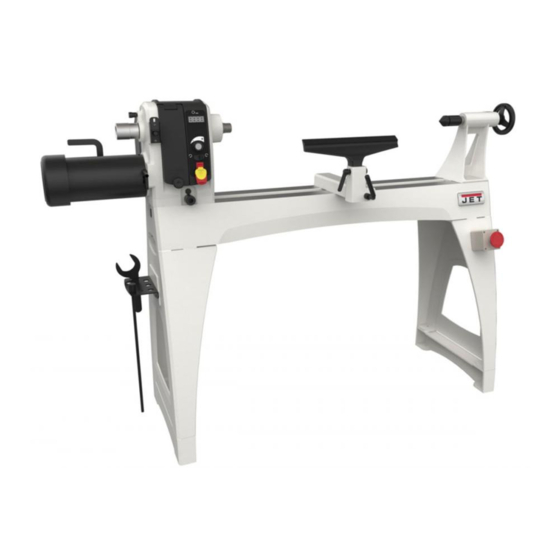
- Page 1 This .pdf document is bookmarked Operating Instructions and Parts Manual 18”x 40” Woodturning Lathe Models JWL-1840EVS, JWL-1840DVR JWL-1840EVS shown 427 New Sanford Road LaVergne, Tennessee 37086 Part No. M-719600 Ph.: 800-274-6848 Edition 3 01/2017 www.jettools.com Copyright © 2017 JET...
-
Page 2: Important Safety Instructions
Do not use this lathe for other than its intended 21. Wood products emit chemicals known to the use. If used for other purposes, JET disclaims State of California to cause birth defects or any real or implied warranty and holds itself other reproductive harm. -
Page 3: About This Manual
Additional knowledge may be obtained from experienced users or trade articles. Whatever accepted methods are used, always make personal safety a priority. If there are questions or comments, please contact your local supplier or JET. JET can also be reached at our web site: www.jettools.com. -
Page 4: Table Of Contents
10.3 Pulley and belt replacement ........................23 11.0 Troubleshooting JWL-1840EVS/DVR Lathes .................... 24 11.1 Electrical and mechanical ........................24 11.2 DRO messages and fault codes (JWL-1840DVR only) ................25 11.3 Motor load display (JWL-1840DVR only) ....................25 12.0 Recommended Lathe Speeds ........................26 13.0 Optional accessories .......................... -
Page 5: Specifications
14.3.2 JWL-1840EVS Controller Assembly – Parts List ................. 33 14.4.1 JWL-1840DVR Controller Assembly – Exploded View ............... 34 14.4.2 JWL-1840DVR Controller Assembly – Parts List ................35 14.5.1 JWL-1840EVS/DVR Bed and Stand Assembly – Exploded View ............36 14.5.2 JWL-1840EVS/DVR Bed and Stand Assembly – Parts List ..............37 14.6.1 JWL-1840EVS/DVR Extension Bed Assembly (OPTIONAL) –... - Page 6 L= length; W=width; H=height The specifications in this manual were current at time of publication, but because of our policy of continuous improvement, JET reserves the right to change specifications at any time and without prior notice, without incurring obligations.
-
Page 7: Setup And Assembly
5.0 Setup and assembly Lathe must disconnected from power during assembly. 5.1 Shipping contents Carton contents (see Figure 5-1) Lathe bed with headstock, tool support and tailstock – A Tool rest – B Legs – C Spur center – D Live single bearing center –... -
Page 8: Tool Shelf
5.4.1 Hoist lifting method The guard (part no. 719002) is optional and purchased separately. website Position straps around lathe bed. information. IMPORTANT: Do not place straps around Loosen set screw on outer collar (shown in spindle, near levers, knobs or other parts that Figure 5-4) with 4mm hex key. -
Page 9: Spindle Comparator (Optional Accessory)
The bed extension can be mounted to the upper or Install comparator spur center into guard lower holes of the lathe at tailstock end, and lower bracket, by lifting up on plunger and inserting holes at headstock end. Mounting in upper holes comparator spur center until its point is about increases spindle... -
Page 10: Electrical Connections
As received from the factory, the JWL-1840EVS necessary, connect equipment- and JWL-1840DVR is ready to run at 230-volt grounding conductor to a live terminal. operation. This tool is intended for use on a circuit Use only 3-wire extension cords that have 3-prong... -
Page 11: Adjustments
Rotate knob (B) clockwise until it engages the 7.0 Adjustments threads. 7.1 Headstock movement Always engage locking handle (A) before operating lathe. 7.1.1 Sliding 7.2 Tailstock movement Push handle (A, Figure 7-1) downward to unlock. Headstock will slide freely along length of bed. To slide tailstock, push locking handle (C, Figure 7- Push handle up to lock. -
Page 12: Tool Rest
Make sure the clamp bushings (K) are pulled apart sufficiently to accept tool rest post. Figure 7-4: cam adjustment Remove stud from end of lathe bed, and slide tailstock off. Turn tailstock on its side, and tighten lock nut Figure 7-6 (F, Figure 7-4) to increase cam pressure, or loosen the nut to relieve cam pressure. -
Page 13: Spur Center: Installing/Removing
To remove a live center: Back off tailstock and remove workpiece from lathe. Loosen quill lock handle (M). Rotate handwheel counterclockwise to retract quill all the way, until live center comes out. Hold the center while doing this to prevent it from falling. -
Page 14: Face Plate: Installing/Removing
If centers do not align, unlock headstock and pivot it slightly. There should be enough “play” in headstock to adjust for this alignment. Lock headstock when finished. 7.15 Speed Range Adjustment (JWL- 1840EVS only) See Figure 7-13. Disconnect lathe from power source. To change speed range, open access door on headstock. -
Page 15: Operating Controls
Machine will slow to a stop, then reverse direction. In education mode, first turn off machine (C) then [The JWL-1840DVR requires about 20 seconds move forward/reverse switch. If switch is moved after shut down due to full capacitor charge. -
Page 16: Operation
Lighting; proper lighting essential eliminate shadows and reduce eye strain. Figure 8-3: JWL-1840DVR mode switch 9.2 Turning Tools 8.2.2 Education mode features If possible, select only good-quality, high-speed steel turning tools. High-speed steel tools hold an When education mode is selected, “EDUC” or edge and last longer than ordinary carbon steel. -
Page 17: Spindle Turning
9.4 Stock Selection Stock for spindles should be straight grained and free of checks, cracks, knots and other defects. It should be cut 1/8" to 1/4" larger than the finished diameter and may require additional length so the ends can be removed later. Larger stock should have the corners removed to produce an octagon making the piece easier to rough down to a cylinder. -
Page 18: Cutting Techniques
Figure 9-5 9.5 Cutting Techniques Figure 9-4 9.5.1 Roughing Out Make sure headstock is locked to lathe bed. Begin with a large roughing gouge. Place the Clean tapered end of spur center and inside of tool on the tool rest with the heel of the tool on headstock spindle. -
Page 19: Face Plate And Bowl Turning
9.5.2 Beads Make a parting cut for what is to be a bead to the desired depth. Place the parting tool on the tool support and move tool forward to make the full bevel of the tool come into contact with the workpiece. - Page 20 9.6.1 Mounting Stock 9.6.2 Faceplate or Chuck? Use of a face plate is the most common method for While faceplates are the simplest, most reliable holding a block of wood for turning bowls and method of holding a block of wood for turning, plates: chucks can also be used.
-
Page 21: Bowl Turning Techniques
other gouges. Most average sized bowl work can 10. Finish turning the outside of bowl with 1/2" or be accomplished with a 3/8" or 1/2" bowl gouge. 3/8" bowl gouge. Leave additional material at base of bowl for support while turning interior. A 1/4"... - Page 22 9.7.3 Sanding and Finishing Remove the tool support and adjust lathe speed to approximately 500 RPM. Higher speeds can build friction while sanding and cause heat check in some woods. Begin with fine sandpaper (120 grit) and progress through each grit, using only light pressure.
-
Page 23: User-Maintenance
10.3 Pulley and belt replacement See Figure 9-12. 3mm hex key required. To change out a belt or pulley, carefully proceed as follows. If you are uncertain about attempting a belt Figure 9-12 or pulley change-out, contact JET technical service... -
Page 24: Troubleshooting Jwl-1840Evs/Dvr Lathes
11.0 Troubleshooting JWL-1840EVS/DVR Lathes 11.1 Electrical and mechanical Table 2 Symptom Possible Cause Correction * Motor fails to develop Power line overloaded. Correct overload condition. full power. Undersized wires in supply system, or Increase supply wire size. extension cord is too long. Low voltage. -
Page 25: Dro Messages And Fault Codes (Jwl-1840Dvr Only)
11.2 DRO messages and fault codes (JWL-1840DVR only) Table 3 Display Possible Cause Correction RSET Significant load spike due To clear, turn off switch, wait for two “beeps”, then turn on to chisel dig-in; or fwd/rev switch. switch moved while in Refer to sect. -
Page 26: Recommended Lathe Speeds
20” to 24” 13.0 Optional accessories These accessory items, purchased separately, can enhance the functionality of your lathe. Contact your dealer to order, or call JET at the phone number on the cover. 719001 ..Tailstock Swing Away 719002 ..Guard 719401 .. -
Page 27: Replacement Parts
Number of your machine available when you call will allow us to serve you quickly and accurately. Non-proprietary parts, such as fasteners, can be found at local hardware stores, or may be ordered from JET. Some parts are shown for reference only, and may not be available individually. -
Page 28: Jwl-1840Evs Headstock Assembly - Parts List
14.1.2 JWL-1840EVS Headstock Assembly – Parts List Index No. Part No. Description Size 1 ....JWL1642-102 .... Spur Center ............. MT2 ....... 1 2 ....6294736 ....Faceplate ..............3" ........1 3 ....6295796 ....Nylon Insert Socket Set Screw ........ 1/4"-20x3/8" ....10 4 .... - Page 29 Index No. Part No. Description Size 60 ....JWL1640EVS-160 ..Pan Head Screw ............#10 - 24 x1” ....8 61 ....JWL1640EVS-161 ..Inverter Upper Cover ..................1 62 ....JWL1840EVS-162 ..Inverter..............VFD015E21A ....1 63 ....JWL1640EVS-163 ..Inverter Lower Box..................1 64 ....
-
Page 30: Jwl-1840Dvr Headstock Assembly - Exploded View
14.2.1 JWL-1840DVR Headstock Assembly – Exploded View... -
Page 31: Jwl-1840Dvr Headstock Assembly - Parts List
14.2.2 JWL-1840DVR Headstock Assembly – Parts List Index No. Part No. Description Size 1 ....JWL1642-102 .... Spur Center ............. MT2 ....... 1 2 ....6294736 ....Faceplate ..............3" ........1 3 ....6295796 ....Nylon Insert Socket Set Screw ........ 1/4"-20x3/8" ....10 4 .... - Page 32 Index No. Part No. Description Size 79 ....TS-0206041 ....Socket Head Cap Screw ......... #10-24x 3/4” ....2 80 ....JWL1221VS-269E ..Wrench (includes #81) ................... 1 81 ....JWL1221VS-270 ..Rubber Grip ....................1 82 ....JWL1640EVS-182 ..Rubber Grip ....................1 83 ....
-
Page 33: Jwl-1840Evs Controller Assembly - Exploded View
14.3.1 JWL-1840EVS Controller Assembly – Exploded View 14.3.2 JWL-1840EVS Controller Assembly – Parts List Index No. Part No. Description Size 1 ....JWL1640EVS-201 ..Knob ......................1 2 ....JWL1640EVS-202 ..Access Door (With Magnets) ................ 1 3 ....TS-2248252 ....Socket Head Button Screw ........M8-1.25Px25 ....1 4 .... -
Page 34: Jwl-1840Dvr Controller Assembly - Exploded View
14.4.1 JWL-1840DVR Controller Assembly – Exploded View... -
Page 35: Jwl-1840Dvr Controller Assembly - Parts List
14.4.2 JWL-1840DVR Controller Assembly – Parts List Index No. Part No. Description Size 1 ....JWL1640EVS-201 ..Knob ......................1 2 ....JWL1640EVS-202 ..Access Door (With Magnets) ................ 1 3 ....TS-2248252 ....Socket Head Button Screw ........M8-1.25Px25 ....1 4 .... -
Page 36: Jwl-1840Evs/Dvr Bed And Stand Assembly - Exploded View
14.5.1 JWL-1840EVS/DVR Bed and Stand Assembly – Exploded View... -
Page 37: Jwl-1840Evs/Dvr Bed And Stand Assembly - Parts List
Index No. Part No. Description Size 1 ....JET-113 ..... JET Nameplate ............113x47mm ....1 2 ....JWL1440-202 .... Bed ........................ 1 3 ....JWL1440-203 .... Stud ....................... 2 4 ....6294742E ....Tool Rest ..............14" ......... 1 5 .... -
Page 38: Jwl-1840Evs/Dvr Extension Bed Assembly (Optional) - Exploded View
14.6.1 JWL-1840EVS/DVR Extension Bed Assembly (OPTIONAL) – Exploded View 14.6.2 JWL-1840EVS/DVR Extension Bed Assembly (OPTIONAL) – Parts List Index No. Part No. Description Size ....719401 ...... 20" Extension Bed w/ Post (includes #1 thru 6) ..........1 1 ....JWL1440-301 .... Extension Bed ............20” ......... 1 2 .... -
Page 39: Jwl-1840Evs/Dvr Guard Assembly (Optional) - Exploded View
14.7.1 JWL-1840EVS/DVR Guard Assembly (OPTIONAL) – Exploded View 14.7.2 JWL-1840EVS/DVR Guard Assembly (OPTIONAL) – Parts List Index No. Part No. Description Size ....719002 ...... Lathe Guard Assembly (includes #1 thru 3) ............ 1 ....JWL1642-179 .... Guard ......................1 2 .... -
Page 40: Electrical Connections
15.0 Electrical connections 15.1 Schematic for JWL-1840EVS only... -
Page 41: Schematic For Jwl-1840Dvr Only
15.2 Schematic for JWL-1840DVR only... -
Page 43: Warranty And Service
JET sells through distributors only. The specifications listed in JET printed materials and on official JET website are given as general information and are not binding. JET reserves the right to effect at any time, without prior notice, those alterations to parts, fittings, and accessory equipment which they may deem necessary for any reason ®... - Page 44 427 New Sanford Road LaVergne, Tennessee 37086 Phone: 800-274-6848 www.jettools.com...
Need help?
Do you have a question about the JWL-1840DVR and is the answer not in the manual?
Questions and answers