Table of Contents
Advertisement
Quick Links
Advertisement
Table of Contents

Related Manuals for Jet JWL-1840VS


Summary of Contents for Jet JWL-1840VS
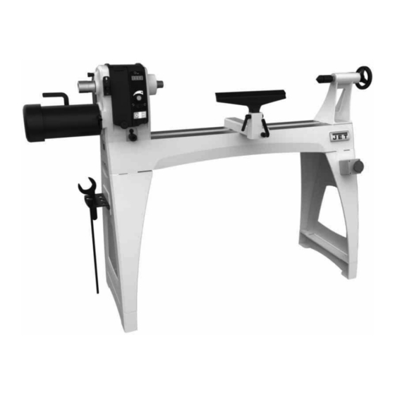
- Page 1 WOOD LATHE JWL-1840VS Original: Operating Instructions Translations: Gebrauchsanleitung Mode d´emploi JPW (Tool) AG Tämplerlistrasse 5 CH-8117 Fällanden Switzerland Phone +41 44 806 47 48 +41 44 806 47 58 www.jettools.com M-719600M 2016 -10...
- Page 2 Déclaration de conformité CE Product / Produkt / Produit: Wood lathe Drechselmaschine Tour à bois JWL-1840VS 719600M Brand / Marke / Marque: Manufacturer / Hersteller / Fabricant: JPW (Tool) AG, Tämperlistrasse 5, CH-8117 Fällanden, Switzerland We hereby declare that this product complies with the regulations Wir erklären hiermit, dass dieses Produkt der folgenden Richtlinie entspricht...
-
Page 3: Table Of Contents
Dear Customer, Many thanks for the confidence you have shown in us with the purchase of your new JET-machine. This manual has been prepared for the owner and operators of a JET JWL-1840EVS wood lathe to promote safety during installation, operation and maintenance procedures. -
Page 4: General Safety Notes
The machine must only be used in a technically perfect Install the machine so that there is sufficient space for safe condition. operation and workpiece handling. When working on the machine, all safety mechanisms and Keep work area well lighted. covers must be mounted. -
Page 5: Remaining Hazards
When sanding, remove the tool rest from the machine. Workpieces with cracks may not be used. 4. Machine specifications Remove the chuck key or dowel pins before turning the 4.1 Machine description machine on. Always close the belt cover. Specifications regarding the maximum or minimum size of the workpiece must be observed. -
Page 6: Noise Emission
Centre above floor without risters 1130mm Overall (LxWxH) 1854 x 1334 x 508 mm Net weight 190 kg Mains 1~230V, PE, 50Hz Output power 1,5 kW (2 HP) S1 Reference current Extension cord (H07RN-F): 3x1,5mm² Installation fuse protection Isolation class 4.3 Noise emission Acoustic pressure level (EN ISO 11202): Idling... - Page 7 Install legs with eight screws, lock washers and flat washers. Tighten screws firmly with 6mm hex key. (see Fig 5). Fig 7 Installing bed extension: (JET Option # 719401) The bed extension can be mounted to the upper or lower holes of the lathe.
- Page 8 Figure 10-1 Spindle comparator (optional accessory) Fig 9 The spindle comparator bracket and centers are optional Top surfaces and inside ways must be flush to allow smooth and purchased separately. movement of tailstock. The spindle comparator consists of two centers inserted Slide tailstock over joint where beds meet, so that clamping into the brackets at rear of lathe.
-
Page 9: Mains Connection
5.3 Mains connection Mains connection and any extension cords used must comply with applicable regulations. The mains voltage must comply with the information on the machine licence plate. The mains connection must have a 10 A surge-proof fuse. Only use power cords marked H07RN-F Connections and repairs to the electrical equipment may only be carried out by qualified electricians. -
Page 10: Turning Between Centres
Speed recommendations The live centre locks into the tail stock taper and can be removed by rotating the handwheel counter clockwise (Fig Workpiece General Roughing Finishing Diameter Cutting < 50 1250 2500 2500 50-100 1600 2500 100-150 1100 1600 150-200 1250 200-250 1100... -
Page 11: Bowl Turning
The live center, shown in Figure 18-1, can be used without the cone. To remove cone from live center, first insert pin through hole in live center body as shown. If pin will not insert at first, rotate cone until pin can be inserted. The cone can now be removed by holding the body stationary while unscrewing cone. -
Page 12: Sanding And Finishing
Mount the face plate with the workpiece already attached onto the spindle nose thread and hand tighten. 7.1 Changing spindle speeds If reversing spindle rotation, make sure face plate, chuck or Never change speeds without the motor running. Damage to other work holding is secured with the set screws, to avoid the variable speed pulleys may result. -
Page 13: Headstock Spindle Lock
On/off switch ( C ): You can start the machine with the green ON-button. The red Off-button stops the machine. Fig 27 Caution: Never press the spindle lock while the spindle is turning! Fig 26-2 7.3 Headstock Rotation The machine will stop when you push the red OFF- is pushed button (C, Fig 26-2) or the E-stop... -
Page 14: Headstock Spindle Index
7.5 Installing work holding The faceplate is used for tuning bowls. There are a number of holes for mounting the workpiece. Thread the faceplate onto the spindle in a clockwise direction, and tighten two setscrews (E, Fig 30). Fig 28-1 For larger workpieces the head stock will have to be turned 90°, the extension added to the tool rest. -
Page 15: Adjusting Tailstock
The live centre (S) can be ejected by turning the hand wheel follows. If you are uncertain about attempting a belt or counter-clockwise. pulley change-out, contact JET technical service or take the headstock to an authorized service center. The live centre pin can be removed to allow deep hole drilling operations. -
Page 16: Changing Belt And Bearings
If replacing a pulley, loosen both set screws (E), and Tailstock moves *Cam lock nut needs adjusting- slide pulley off spindle. Tighten cam lock nut. Install new pulley, loosely securing the two set screws. *Bed and tailstock mating surfaces greasy or oily- Make sure pulley is oriented properly and key is Remove tailstock and clean surfaces inserted properly in spindle groove. - Page 17 Stock number 708349 Heavy outboard turning stand Refer to the JET-Pricelist for various tools and work holding. Stock number 719601 Spindle Comparator Kit...
Need help?
Do you have a question about the JWL-1840VS and is the answer not in the manual?
Questions and answers