Table of Contents
Advertisement
Quick Links
This .pdf document is bookmarked
Operating Instructions and Parts Manual
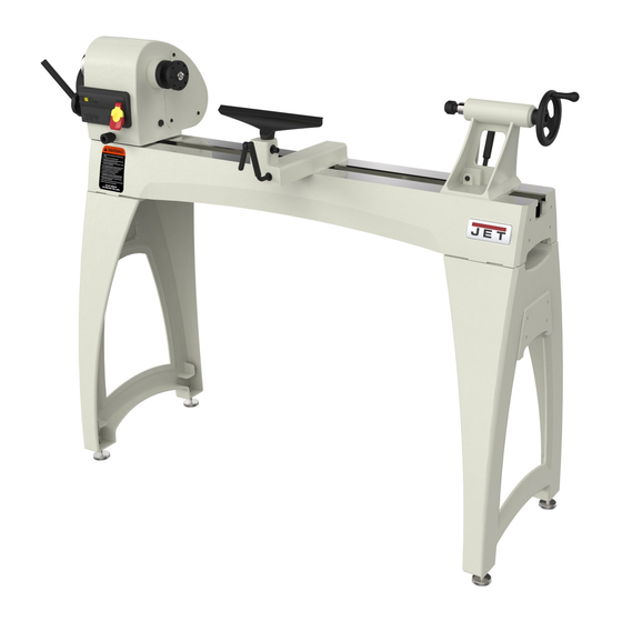
14"x 40" Woodturning Lathe
Model JWL-1440VS
Shown with optional 20-inch extension bed (#719401)
JET
427 New Sanford Road
Part No. M-719400
LaVergne, Tennessee 37086
Revision E 12/2020
Ph.: 800-274-6848
ECR 20091409169
www.jettools.com
Copyright © 2014 JET
Advertisement
Table of Contents

Related Manuals for Jet JWL-1440VSK


Summary of Contents for Jet JWL-1440VSK
- Page 1 Operating Instructions and Parts Manual 14”x 40” Woodturning Lathe Model JWL-1440VS Shown with optional 20-inch extension bed (#719401) 427 New Sanford Road Part No. M-719400 LaVergne, Tennessee 37086 Revision E 12/2020 Ph.: 800-274-6848 ECR 20091409169 www.jettools.com Copyright © 2014 JET...
-
Page 2: Warranty And Service
JET sells through distributors only. The specifications listed in JET printed materials and on official JET website are given as general information and are not binding. JET reserves the right to effect at any time, without prior notice, those alterations to parts, fittings, and accessory equipment which they may deem necessary for any reason ®... -
Page 3: Table Of Contents
2.0 Table of contents Section Page 1.0 Warranty and Service ............................. 2 2.0 Table of contents ............................3 3.0 Safety warnings .............................. 4 4.0 About this manual ............................5 5.0 Specifications ..............................6 5.1 JWL-1440VS hole pattern .......................... 7 ... -
Page 4: Safety Warnings
32. Do not use this JET wood lathe for other than 16. Read and understand warnings posted on the its intended purpose. If used for other purposes, machine and in this manual. Failure to comply... -
Page 5: About This Manual
Additional knowledge may be obtained from experienced users or trade articles. Whatever accepted methods are used, always make personal safety a priority. If there are questions or comments, please contact your local supplier or JET. JET can also be reached at our web site: www.jettools.com. -
Page 6: Specifications
5.0 Specifications Model number ............................JWL-1440VS Stock numbers: Lathe with Leg Set ............................719400K Lathe only ............................... 719400 Leg Set only ..............................719403 Bed Extension 20”, with tool post (optional accessory) ................... 719401 Motor and electricals: Motor type ................totally enclosed fan cooled, induction, capacitor start Horsepower ............................ -
Page 7: Jwl-1440Vs Hole Pattern
Optional Bed Extension only ..............49.5 lb (22.5 kg) ....56 lb (25 kg) The specifications in this manual were current at time of publication, but because of our policy of continuous improvement, JET reserves the right to change specifications at any time and without prior notice, without incurring obligations. -
Page 8: Setup And Assembly
6.2 Unpacking and cleanup 6.0 Setup and assembly Remove all smaller items from main carton. Do not discard carton or packing material until lathe 6.1 Shipping contents is assembled and running satisfactorily. Carton contents for # 719400K (see Figure 2) Inspect contents for shipping damage;... -
Page 9: Mounting Bed Extension (Optional Accessory)
Use straps in The 20” bed extension (p/n 719401) is optional and good condition. Straps/lifting mechanisms must purchased separately. See your JET dealer for be properly rated for lathe weight. information. If you did not purchase the bed 6.4.1 Hoist lifting method... -
Page 10: Electrical Connections
replacement of the electric cord or plug is necessary, do not connect the equipment-grounding conductor to a live terminal. Check with qualified electrician or service personnel if the grounding instructions are not completely understood, or if in doubt as to whether the tool is properly grounded. -
Page 11: Voltage Conversion
7.2 Voltage conversion 8.2 Headstock rotation To switch the incoming power leads for 230 volt Loosen handle (A, Figure 9). operation: Unscrew the knurled knob (B) counter- Remove the junction box cover on the motor clockwise until it can be pulled outward. and reconnect the leads according to the Pull knob outward and rotate headstock to diagram inside the cover. -
Page 12: Cam Tightness
8.5 Tool rest A 12-inch tool rest is provided with your lathe. It is designed to allow adjustment for height, position on the bed, and angle to the work. Loosen locking handle on tool rest base (G, Figure 12) to slide base forward or back, and to angle it to the bed. -
Page 13: Spur Center: Installing/Removing
for example, when cutting flutes on a spindle blank with a hand-held router, while the spindle blank is secured between lathe centers. The JWL-1440VS lathe provides 36 indexing positions. These are identified in the chart in section 15.0. Figure 15 8.10 Live center: Installing/removing The live center is installed into the tailstock quill. -
Page 14: Face Plate: Installing/Removing
9.0 Operating controls Refer to Figure 19. On/off switch (A): Pull to start lathe, push to stop. The safety key (A ) can be removed to prevent unauthorized use of lathe. The safety key must be inserted to restart the lathe. Figure 17 8.12 Face plate: Installing/removing Disconnect lathe from power source. -
Page 15: Operation
Square Scraper (Bedan) – 3/8” or 1/2", used to When the speed is decreased, the pulleys act in opposite fashion. create square shoulders. Large Round Nose (Domed) Scraper – 1-1/2", Change speed while the lathe used to reduce ridges on interior of bowls, round spindle is turning to avoid overstressing the edges of bowls, etc. -
Page 16: Spindle Turning
will save trips to the grinder and keep the edge Drive the spur center about 1/4” into the fresh. workpiece, using a wood mallet or dead blow hammer as shown in Figure 24. Be careful that 10.3 Spindle Turning you do not split the workpiece. Spindle turning takes place between the centers of the lathe. -
Page 17: Cutting Techniques
10.5.2 Beads 12. Start lathe at lowest speed and bring it up to the appropriate RPM for the size of workpiece Make a parting cut for what is to be a bead to used. Consult digital readout on the headstock. the desired depth. -
Page 18: Face Plate And Bowl Turning
Select stock at least 1/8" to 1/4" larger than each dimension on the finished workpiece. Always select the largest diameter face plate that can be used for the workpiece to be turned. True one surface of the workpiece for mounting against the face plate. -
Page 19: Bowl Turning Techniques
10.7 Bowl Turning Techniques A chuck is not a requirement, but is handy when working on more than one piece at a time. Rather 10.7.1 To Shape Outside of Bowl than removing screws, you simply open the chuck and change workpieces. Odd shaped burls, crotches and other irregular shaped blanks require special preparation The most popular ones are four jaw scroll chucks... - Page 20 Develop wall thickness at the rim and maintain it as you work deeper into the bowl (Once the piece is thin toward the bottom, you cannot make it thinner at the rim). When the interior is finished, move the tool support to exterior to re- define bottom of bowl.
-
Page 21: User-Maintenance
JET authorized service center replace the belt and/or bearings. Clean and oil the lathe bed so that headstock, tailstock and tool rest base will slide easily. -
Page 22: Optional Accessories
12.0 Optional accessories This accessory item, purchased separately, can enhance the functionality of your lathe. Contact your dealer to order, or call JET at the phone number on the cover. 719401 ..20" Extension Bed w/ Post 719001..Tailstock Swing Away 13.0 Recommended Lathe Speeds... -
Page 23: Troubleshooting The Jwl-1440Vs Lathe
14.0 Troubleshooting the JWL-1440VS Lathe Table 3 Symptom Possible Cause Correction Motor fails to develop Power line overloaded. Correct overload condition. full power. Undersized wires in supply system, or Increase supply wire size. extension cord is too long. Running capacitor is bad. Replace running capacitor. -
Page 24: Indexer Positions
15.0 Indexer Positions How to use the chart A diagram of the indexer is shown at right, as viewed from the tailstock end of the Lathe. Points A, B and C are the holes in the head casting. The holes in the spindle collar may be considered as numbered 1 through 12. -
Page 25: Replacement Parts
16.0 Replacement Parts Replacement parts are listed on the following pages. To order parts or reach our service department, call 1-800- 274-6848 Monday through Friday, 8:00 a.m. to 5:00 p.m. CST. Having the Model Number and Serial Number of your machine available when you call will allow us to serve you quickly and accurately. 16.1.1 JWL-1440VS Headstock Assembly –... -
Page 26: Jwl-1440Vs Headstock Assembly - Parts List
16.1.2 JWL-1440VS Headstock Assembly – Parts List Index No. Part No. Description Size 1 ....JML-3 ......Spur Center ............. MT2 ......1 1A ....JML-3A ...... Center Point for Spur Center ................. 1 2 ....JWL1440-102 .... Faceplate ..............3" ........1 3 .... - Page 27 Index No. Part No. Description Size 59 ....JWL1440-159 .... Motor Pulley Assembly .................. 1 61 ....JWL1440-161 .... Motor (includes #62) ..................1 ....JWL1440-MF ..... Motor Fan (not shown)................... 1 ....JWL1440-MFC ..Motor Fan Cover (not shown) ................ 1 ....
-
Page 28: Jwl-1440Vs Bed Assembly - Exploded View
16.2.1 JWL-1440VS Bed Assembly – Exploded View... -
Page 29: Jwl-1440Vs Bed Assembly - Parts List
16.2.2 JWL-1440VS Bed Assembly – Parts List Index No. Part No. Description Size 1...JETSTRIPE-8X3.5B ..JET Stripe ...................... 1 2 ....JWL1440-202 .... Bed ........................ 1 3 ....JWL1440-203 .... Stud ....................... 2 4 ....JWL1442-205 .... Tool Rest ..............12" ......... 1 5 .... -
Page 30: Jwl-1440Vs Leg Set - Exploded View
16.3.1 JWL-1440VS Leg Set – Exploded View 16.3.2 JWL-1440VS Leg Set – Parts List Index No. Part No. Description Size ....719403 ...... JWL-1440VS Leg Set (includes #1 thru 10) ..........1 1 ....JWL1840EVS-350 ..Leg ......................... 2 2 .... -
Page 31: Jwl-1440Vs Extension Bed Assembly (Optional) - Exploded View
16.4.1 JWL-1440VS Extension Bed Assembly (OPTIONAL) – Exploded View 16.4.2 JWL-1440VS Extension Bed Assembly (OPTIONAL) – Parts List Index No. Part No. Description Size ....719401 ...... 20" Extension Bed w/ Post (includes #1 thru 6) ..........1 1 ....JWL1440-301 .... Extension Bed ............20” ......... 1 2 .... -
Page 32: Electrical Connections
17.0 Electrical Connections...
Need help?
Do you have a question about the JWL-1440VSK and is the answer not in the manual?
Questions and answers