Table of Contents
Advertisement
Quick Links
ACTIVAL
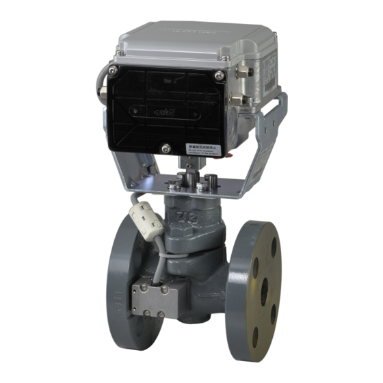
Motorized Two-Way Valve with Flanged-End Connection
General
ACTIVAL
Flow Measurement and Control Valve Model
FVY5137J is a series of motorized two-way valves with
1
flanged-end connection. 1
/
integrated in a single unit.
In combination with the functions of a control valve, Model
FVY5137J measures and controls flow. Model FVY5137J thus
enables to control temperature for air conditioning by controlling
chilled/hot water volume and to measure chilled/hot water flow.
For such a high functionality, compact size and simple
installation of Model FVY5137J are incomparable.
Model FVY5137J is operated by the following control signal.
- 4 to 20 mA DC input:
Provides proportional control in combination with a single
loop controller. (e.g., Model SDC35/SDC36)
Flow data stored in Model FVY5137J is retrieved via RS-485
communication (Modbus protocol). The retrieved flow data is
effective for energy-saving facility operation.
Features
Compact and lightweight:
Rotary valve actualizes small body and light weight.
Valve and actuator integrated in a single unit.
Model
FVY5137J
holds
maintenance and energy-saving facility operation. The
data is retrieved via RS-485 communication (Modbus
protocol).
Valve for chilled/hot water control applicable to large Cv
value, high rangeability, and low leakage.
Durable actuator with low power consumption.
IMPORTANT:
Do not use the data measured by Model FVY5137J for charging or dealing purposes.
*
This product was designed and manufactured conforming to the ISO (International Organization for Standardization, PN10/GG-20).
Flow Measurement and Control Valve
Standalone Model
(145 psig / Gray cast iron)*
" to 3" rotary valve and actuator are
2
flow
data
effective
Flow control/position control operation selectable:
For flow control, flow characteristic is selectable (equal
percentage or linear). For position control, flow
characteristic is equal percentage.
for
In
combination
QY5010S1000) and the insertion-type pipe temperature
sensor (Model TY7830) or the temperature sensor for
pipe surface (Model TY7820), pressure, temperature,
and flow can be displayed on the Display Panel.
CE Marking certified product:
Models FVY5137J conforms to all the applicable
standards of CE Marking.
© 2015–2016 Azbil Corporation All Rights Reserved.
1
AB-7350-U
Specifications/Instructions
with
Display
Panel
(Model
Advertisement
Table of Contents

Related Manuals for Azbil ACTIVAL FVY5137J


Summary of Contents for Azbil ACTIVAL FVY5137J
- Page 1 CE Marking. IMPORTANT: Do not use the data measured by Model FVY5137J for charging or dealing purposes. This product was designed and manufactured conforming to the ISO (International Organization for Standardization, PN10/GG-20). © 2015–2016 Azbil Corporation All Rights Reserved.
-
Page 2: Safety Instructions
If this product is used in a clean room or a place where particularly high reliability or control accuracy is required, please contact our sales representative. Azbil Corporation will not bear any responsibility for the results produced by the operators. - Page 3 IMPORTANT: In case an Azbil Corporation product fails, you are required to provide your Equipment with safety design such as fool-proof design* , and fail-safe design* (anti-flame propagation design, etc.), whereby preventing any...
-
Page 4: Model Numbers
AB-7350-U IMPORTANT: Install the product to a pipe so that they are electrically connected at the same potential. If the valve and the pipe are electrically isolated, noise might be generated, causing incorrect measurement and control of flow. When installing the product with flange gasket, do not use the rubber gasket or the gasket that goes inside the pipe. -
Page 5: Valve Specifications
AB-7350-U Specifications For weight, refer to the table shown in the section Dimensions. Valve and actuator (as a single unit) specifications Item Specification -4 to 122 F (-20 to 50 °C) Environmental Rated operating conditions Ambient temperature conditions (Do not allow the process fluid to freeze.) Ambient humidity 5 to 95 % RH... - Page 6 AB-7350-U Actuator specifications Item Specification 24 V AC 15 %, 50 Hz/60 Hz Power supply Power consumption 8 VA 63 5 sec (50 Hz) / 53 5 sec (60 Hz) Timing 4 to 20 mA DC input (Input impedance: 250 ) Control signal Model FVY5137J Input type...
- Page 7 AB-7350-U Measuring range and accuracy IMPORTANT: Flow measuring accuracy shown in the below is for the valve sensor measuring 44.6 to 62.6 F (7 to 17 °C) and 113 to149 F (45 to 65 °C) ranges, 29 to 261 psig pipe pressure, and 4.35 to 43.5 psig differential pressure. Without these ranges, the flow rate measuring accuracy might decrease.
-
Page 8: Wire Specifications
AB-7350-U Data in Model FVY5137J Data type Description Flow data Following items are displayed on Display Panel (Model QY5010S1000): Actual flow, supply water temperature, return water temperature, valve inlet pressure, valve outlet pressure, actual flow (% in bar graph), actual valve position (% in bar graph) Following items are retrieved via RS-485 communication (Modbus protocol): Control setting value, actual valve position, actual flow, set flow, supply water temperature, return water temperature, valve inlet pressure, valve outlet pressure, instantaneous energy, totalized flow, totalized... -
Page 9: Parts Identification
AB-7350-U Dimensions Model with 1½" to 3" valve 2.76” (70mm) 2.76” (70mm) 3.23" (82mm) 3.35" (85mm) Flow direction indication N × h Dia. Valve sensor cable Valve sensor (in valve sensor cover) Valve size Weight Model number Unit 1½" 9.49 4.06 6.50... - Page 10 AB-7350-U Actuator details (Connectors, ports, terminals, and LED) Reset switch Connector for Pt100 input Row T1: Supply water temperature Connector for Connector for Row T2: Return water temperature RS-485 communication Display Panel Operating status LED (red) Port for Port for valve sensor cable Display Panel cable Port for...
-
Page 11: Precautions For Installation
AB-7350-U Installation Precautions for installation WARNING Some of the product models weigh more than 40 lb (18.1 kg). Carefully move the product with a vehicle or enough manpower in an appropriate manner. Careless lift or accidental drop of the product might cause injury or product damage. - Page 12 AB-7350-U Installation location CAUTION Do not install the product nearby a steam coil, pressurized hot-water coil, or any high heat source. High temperature radiation might cause malfunction of its actuator. Do not use the product in an atmosphere corrosive to the actuator, valve, and their components. Doing so might ...
-
Page 13: Mounting Position
AB-7350-U Mounting position Model FVY5137J can be mounted in any position ranging from upright to sideways (90 tilted). Note that Model FVY5137J must be installed with the valve sensor vertically positioned above the valve body when being tilted. It is also installable on the vertical upflow pipe. - Page 14 AB-7350-U Factory preset position The actuator shaft is positioned at 100 % (in fully open position) for shipment. The shaft is thus completely turned clockwise, and the pointer points at ‘100’. (See Fig. 6.) Pointer Figure 6. Pointer position for shipment ...
-
Page 15: Wiring Procedure
AB-7350-U Wiring WARNING Detach the cover only when wiring, setting the product or maintenance and reattach the cover after wiring, setting the product or maintenance. Failure to do so might cause electric shock. Before wiring or maintenance, be sure to turn off the power to the product. Failure to do so might cause electric shock ... - Page 16 AB-7350-U 3) Refer to Figs. 3 and 10 and correctly connect the wires to the M3.5 screw terminals. Note that the wires of the temperature sensor, Display Panel, and RS-485 communication lines are connected to the connectors. Figure 10. Terminals arrangement 4) Separate the power supply line from the signal lines.
- Page 17 AB-7350-U 3) Unplug the 6-pin connector for temperature sensor (Pt100 input) from the actuator socket, and connect the sheath stripped wires (3-core cable of the temperature sensor (Pt100 input)) to the connector. Insert a slotted screwdriver (with 0.1" x 0.02" (2.5 x 0.4 mm) blade tip) into a square hole of the connector for clamp release. The screwdriver successfully releasing the clamp remains the inserted position.
- Page 18 AB-7350-U 3) Unplug the 6-pin connector for RS-485 communication from the actuator socket, and connect the sheath stripped wires to the connector. Insert a slotted screwdriver (with 0.1" x 0.02" (2.5 x 0.4 mm) blade tip) into a pocket on the top/bottom of the connector for clamp release.
- Page 19 AB-7350-U Solid line: Isolated, Dashed line: Not isolated Power T1 (Supply water temperature) T2 (Return water temperature) Pulse output Internal circuit Display Panel DI (Cooling/heating switch signal) RS-485 communication In Control signal input RS-485 communication Out Figure 20. Internal isolation Single transformer with two products (See Fig.
-
Page 20: Connection Examples
AB-7350-U Connection examples Controller (e.g. Model SDC35/ SDC36TC0) Isolator* Controller Isolator* Model FVY5137 Model FVY5137 (e.g. Model SDC35/ (4 to 20 mA input) (4 to 20 mA input) SDC36TC0) Controller Isolator* Isolator* Power Power Model FVY5137 Model FVY5137 Power (e.g. - Page 21 AB-7350-U Slave (Model SDC series) Master Slave (Model FVY5137J: this product) Figure 25. Connection example: 3-wire RS-485 communication Slave (Model SDC series) Master Note: This product has 3-wire communication line connection. The example shows 5-wire communication line connection of the master device. Slave (Model FVY5137J: this product) Figure 26.
- Page 22 AB-7350-U Cable Gland with Three Ports Cable gland with three ports (Model DY7000A1000) is recommended to attach to a wiring port (knockout) of this product when RS-485 communication line and signal line are passed through the same wiring port. The cable gland with three ports is applicable to cables for small power.
- Page 23 AB-7350-U 4) Lift and remove the cover from the base. Cover Plug for non-used port Lock nut Latches Base Figure 29. Cover removal from the base Attaching the cover to the base Attach the cover to the base and fix them by locking the 3 latches. 1) Attach the cover to the base by simultaneously inserting the 3 male latches of the cover to the 3 female latches of the base.
- Page 24 AB-7350-U 3) Connect the seal connectors (optional) to the cover of the cable gland. IMPORTANT: When tightening a seal connector to the cover, be sure not to press excessive force on the latches. Seal connectors (optional) Cover of the cable gland Figure 31.
- Page 25 AB-7350-U 7) Process the wire ends and connect them to the terminals/connectors. IMPORTANT: If a terminal lug without insulation sleeve is crimped on a wire end, use a tube marker for safety. During wire termination, do not allow any foreign objects including chips and stripped insulation to get inside the product.
-
Page 26: Inspection And Troubleshooting
AB-7350-U Inspection and Troubleshooting WARNING Some of the product models weigh more than 40 lb (18.1 kg). Carefully move the product with a vehicle or enough manpower in an appropriate manner. Careless lift or accidental drop of the product might cause injury or product damage. - Page 27 AB-7350-U 0.39" 0.39" (1 cm) (1 cm) Pointer Lower setscrew of the terminal cover Figure 34. Check of the valve position detecting accuracy...
- Page 28 AB-7350-U ACTIVAL is a trademark of Azbil Corporation in Japan or in other countries. Rev. 4.0 Jun. 2016 AB-7350-U...
Need help?
Do you have a question about the ACTIVAL FVY5137J and is the answer not in the manual?
Questions and answers