
Related Manuals for Azbil MagneW FLEX+


Summary of Contents for Azbil MagneW FLEX+
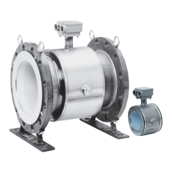
- Page 1 CM2-MGG120-2001 MagneW FLEX+/PLUS+ Electromagnetic Flowmeter Explosion-proof type Detector Model: MGG15/17 User's Manual...
- Page 2 Copyright, Notices and Trademarks MagneW is a trademark of Azbil Corporation in Japan and/or other countries. © 1997–2019 Azbil Corporation. All Rights Reserved.
- Page 3 Thank you for purchasing the MagneW FLEX+/PLUS+ Electromagnetic Preface Flowmeter. This product is a highly reliable, high performance electromagnetic flowmeter developed based on our extensive experience in the field. The unique high-quality lining molding technique and many other special fea- tures make this product deliver outstanding flow rate measurement.
- Page 4 Unpacking and Inspection Unpacking This device is a precision instrument and should be handled with care to pre- the MagneW vent damage or breakage. FLEX+/PLUS+ After unpacking the device, verify that the following items are included: • The detector itself •...
- Page 5 Safety Precautions Correct installation, correct operation and regular maintenance are essential to Introduction ensure safety during the use of this device. Read and understand the safety precautions described in this manual and be sure to follow the instructions on installation, operation and maintenance. Safety precautions in this manual are of two kinds —Warning and Caution.
- Page 6 How this Manual is Organized and Used This manual explains the use of the device and its associated devices in the Organization and method of use following order: Chapter 1 The configuration of measuring systems using this product, the structure of the detector, and the names and functions of the respective parts.
-
Page 7: Table Of Contents
Detailed Table of Contents Chapter 1 - Configuration and Structure of the Measuring System ................1 - 1 Introduction ............... 1 - 1 System Configuration ............1 - 2 Measuring System ............1 - 2 Structure of this Unit and Functions of Parts ....1 - 3 Detector ................ - Page 8 Figures and Tables Figure 1-1 Integral Configuration ............1 - 2 Figure 1-2 Remote Configuration ............1 - 3 Figure 1-3 Details of the Detector ............1 - 4 Figure 1-4 Details of the Wafer Detector ........... 1 - 6 Figure 1-5 Details of the Flanged Detector ........
- Page 9 Figure 2-31 Detector Installation Using Non-SUS Material Grounding Ring (with rubber gasket) ............2 - 41 Figure 2-32 Connection Using a Special Cable ........2 - 42 Figure 2-33 Grounding Via the External Grounding Terminal ....2 - 43 Figure 2-34 Example of Installation (union assembly) ......
-
Page 10: Chapter 1 - Configuration And Structure Of The Measuring System
Chapter 1 - Configuration and Structure of the Measuring System This chapter explains the configuration of measuring systems using this unit. Introduction • The structure of this unit and the names and functions of its respective parts are explained. 1 - 1... -
Page 11: 1-1 System Configuration
1-1 System Configuration Measuring System Depending on how it is combined with the converter, this product is available in Introduction two configurations, integral and remote. • Remote: Detector and converter are installed connectly by cable. Figures 1-1 show examples of measurement systems using the Examples of flow measurement device. -
Page 12: 1-2 Structure Of This Unit And Functions Of Parts
1-2 Structure of this Unit and Functions of Parts Detector The functions and structure of the device are as follows. Explanation • When a fluid passes through the detector, the detector generates an electro- motive force signal proportional to the flow rate. •... - Page 13 Detector Continued This table explains the major parts of the detector. Names and func- tions of parts Function Name Flow direction mark • Indicates the direction of fluid flow. • Mount the detector so that the measured fluid flows in the direction indicated by this mark. Electrodes •...
- Page 14 Detector Continued Figure 1-3shows the structure of the detector and the names of its major parts. Names of major parts of the flange type Figure 1-3 Details of the Flanged Detector Terminal box Grounding Pressure-resistant cover terminal packing cable adapter Terminal (only for TIIS) Flow direction...
- Page 15 Detector Continued This table explains the major parts of the detector. Names and func- tions of parts Function Name • Indicates the direction of fluid flow. Flow direction mark • Mount the detector so that the measured fluid flows in the direction indicated by this mark. Electrodes •...
- Page 16 Figure 1-4 Cable adapter with flameproof packing Figure 1-5 Details of the cable adapter with flameproof packing 1 - 7...
-
Page 17: Detector Terminal Box
Detector Terminal Box Figure 1-6 Detector Terminal Box Names of parts Signal terminals Conduit wiring connectors Excitation terminals Grounding terminal The table below explains the major parts of the detector terminal box. Names and explanations of parts Name Explanation • These are marked A, B, and C. Signal terminals Excitation terminals •... -
Page 18: Use Of Explosion-Proof Electromagnetic Flowmeters For Tiis
1.3 Use of Explosion-proof Electromagnetic Flowmeters for TIIS This flowmeter is of flameproof structure. Read this item carefully to ensure Before use correct use. Flameproof structure means a totally enclosed housing that is capable of with- Flameproof structure standing an explosion of a gas or vapor within it, and of preventing the igni- tion of an explosive gas or vapor that may surround it. - Page 19 The flowmeter is required to pass a certified examination conducted in accor- Nameplates dance with Industrial Safety and Hygiene Regulations. The Industry Safety Engineering Association authorizes the flowmeter to carry a certified name- plate only after passing the examination. Figure 1.6 Certified Nameplate 1 - 10...
-
Page 20: Use Of Explosion-Proof Electromagnetic Flowmeters For Fm/Csa
1.4 Use of Explosion-proof Electromagnetic Flowmeters for FM/CSA This flowmeter is of flame-proof (Explosion-protection) structure. Read this Before use item carefully to ensure correct use. Flameproof structure means a totally enclosed housing that is capable of with- Flameproof (Explosion- standing an explosion of a gas or vapor within it, and of preventing the igni- protection) tion of an explosive gas or vapor that may surround it. - Page 21 If an MGG18/19 detector is used with an MGG14C converter as an FM-approved nonincendive product, both the detector and the converter should be FM-approved nonincendive products. If they are not, the MGG18/19 detector cannot be used as an FM-approved nonincendive product. 1 - 12...
-
Page 22: Chapter 2 - Installing The Device
Chapter 2 - Installing the Device This section describes the installation and wiring of Electromagnetic Introduction Flowmeter. The required parts and method for installing this device may vary slightly depending on the material of the wetting ring and the pipe. Installation is explained in the following order: •... -
Page 23: 2-1 Before Installing
2-1 Before Installing Criteria for Selecting the Installation Site (1) In order to make full use of the functions of the device, select an optimal Introduction installation site by following the selection criteria below. Environment Caution • Install the unit in a location with an ambient temperature of –25 to +60°C and a relative humidity of 5% to 100%. - Page 24 Criteria for Selecting the Installation Site (1) Continued Fluid to be Caution measured (continued) • The fluids listed below could cause measurement trouble. Do not use this device, therefore, even if their conductance, temperature, and pressure fall within the specifications of the device (see Ap- pendix A, "Device Standard Specifications and Model Numbers.") (1) Fluids that have sufficient conductance at high temperatures but do not satisfy the conductance requirements at room tem-...
-
Page 25: Figure 2-1 Proper Placement Of The Detector
Criteria for Selecting the Installation Site (2) • Position the detector so that its internal detector passage is continuously Detector position filled with the fluid being measured. Figure 2-1 shows examples of posi- tions that fulfill this condition. Figure 2-1 Proper Placement of the Detector Air is easily traped. -
Page 26: Figure 2-3 Space Allowance For Inspections
Criteria for Selecting the Installation Site (2) Continued • Although a pipe section is not necessary on the downstream side, se- Detector position (continued) cure a section of at least 2D if drift current or similar is likely. • Select a place where there is no major pulse flow. (Install the detector in a location distant from a pump.) •... -
Page 27: Directions Of The Terminal Box And The Converter
Directions of the Terminal Box and the Converter In some locations, the direction of the terminal box or the converter may be Introduction unsuitable if the detector is installed as it is shipped. In such a case, the termi- nal box or the converter can be repositioned. After selecting a installation site, adjust the direction of the terminal box or the converter in advance by the two methods shown below. -
Page 28: Figure 2-4 Repositioning The Terminal Box Or Converter
Directions of the Terminal Box and the Converter Continued Figure 2-4 Repositioning the Terminal Box or Converter Repositioning the terminal box or con- verter (continued) Hex wrench Caution • After removing the screws, do not pull hard on the terminal box or converter. -
Page 29: 2-2 Method Of Installation
2-2 Method of Installation 2-2-1 Installing a Wafer Detector Basic Installation Method The device can installed as a wafer, flange, union, hose, or clamp unit. Refer- Introduction ring to the appropriate method of installation, install the unit properly. Figure 2-5 shows the basic method for installing the device. Installation example Figure 2-5 Device Installation Example Nuts (optional) -
Page 30: Figure 2-6 Flange Shape
Basic Installation Method Continued Fastening torque Caution • Table 2-1 shows the fastening torque for each pipe bore. Using centering hardware, apply the prescribed fastening torque to pre- vent any liquid leak from the pipe. Table 2-1 Fastening Torque Levels Nominal Detector Bore Fastening Torque 2.5 - 15A... -
Page 31: Figure 2-7 Examples Of Unacceptable Installation (1)
Basic Installation Method Continued Flange shape Warning (continued) • Before installing the detector make sure that the pipe is exactly straight and centered. Any irregularity in these respects could cause leakage or other hazards. Figure 2-7 Examples of Unacceptable Installations (1) Tilted pipe Off center Off center... -
Page 32: Parts Necessary For Installation
Parts Necessary for Installation The following parts are necessary for the installation of the detector: Introduction • Centering nuts (four supplied) • Connecting bolts and nuts (available separately) • Gaskets: Required when using grounding rings made of SUS material. Not required when using grounding rings made of hastelloy, tita- nium, tantallum, or platinum. -
Page 33: Table 2-2 Recommended Inner Diameters Of Gaskets
Parts Necessary for Installation Continued Gaskets are supplied with the grounding ring, except when it is made of SUS Gaskets material. Secure gaskets when you use a grounding ring made of SUS mate- rial. We recommend gasket material such as joint sheet or PTFE. For the bore diameters of the gaskets, refer to Table 2-2. -
Page 34: Selecting An Installation Method
Selecting an Installation Method Caution • The necessary materials and the installation method vary accord- ing to the material of the ring and that of the pipe on which the detector is to be installed. Select the appropriate method of instal- lation after confirming the specifications of the detector to be in- stalled and the conditions of installation. - Page 35 Installation on Horizontal Pipe Caution • Improper installation may result in leakage or damage to the pipe flanges. The following parts are required: Parts required • Through-bolts and nuts • Centering nuts • Gaskets: The required gasket material will vary according to the material of the pipe on which the detector is to be installed.
- Page 36 Installation on Horizontal Pipe Continued Procedure Step Action Drawing (continued) • Make sure that the detector re- mains properly centered. • Make sure that the gaskets do not protrude beyond the edges of the pipe flanges. • When you have checked these items, insert the remaining through-bolts into the flange holes and tighten the bolts...
- Page 37 Installation on Vertical Pipe Caution • Improper installation may result in leakage or damage to the pipe flanges. The following parts are required: Parts required • Through-bolts and nuts • Centering nuts • Gaskets: The required gasket material will vary according to the material of the pipe on which the detector is to be installed.
- Page 38 Installation on Vertical Pipe Continued Procedure Step Action Drawing (continued) Insert through-bolts fitted with one centering nut each into the remaining two flange holes shown by black dots in Steps 1 and 2. • Make sure that the detector re- mains properly centered.
-
Page 39: Figure 2-11 Installation Using Sus Material Grounding Ring And Metal Pipe
Installation on Metal Pipe (1) The installation method described in this section corresponds to the following Introduction combination of pipe and grounding ring materials. For the installation method corresponding to any other combination, refer to the table on page 2-13. Pipe material: Metal Grounding ring material: SUS material The following parts are required:... -
Page 40: Installation On A Pipe
Installation on Metal Pipe (2) The installation method described in this section corresponds to the following Introduction combination of pipe and grounding ring materials. For the installation method corresponding to any other combination, refer to the table on page 2-13. Pipe material: metal Grounding ring material: other than SUS material The following parts are required. -
Page 41: Figure 2-12 Installation Using Non-Sus Material Grounding Ring And Metal Pipe
Installation on Metal Pipe (2) Continued • Install the detector as shown in Figure 2-12. See Table 2-1 on page 2-9 for Installation procedure the appropriate fastening torque. • To use rubber gaskets for a low fastening torque, refer to page 2-25. Caution •... - Page 42 Installation on PVC Pipe (1) The installation method described in this section corresponds to the following Introduction combination of pipe and grounding ring materials. For the installation method corresponding to any other combination, refer to the table on page 2-13. Pipe material: PVC Grounding ring material: SUS material The following parts are required:...
-
Page 43: Figure 2-14 Installation Using Sus Material Grounding Ring
Installation on PVC Pipe (1) Continued The installation procedure varies with such conditions as the fastening torque Installation procedure and the need for a protective plate. Choose one of the following three meth- ods as applicable. 1. Use this method to install the detector with a specified fastening torque. Install the detector as shown in Figure 2-14. -
Page 44: Figure 2-15 Installation Using Sus Material Grounding Ring (With Protective Plate)
Installation on PVC Pipe (1) Continued 2. Use this method to install the detector using a protective plate to prevent Installation procedure the PVC pipe from being deformed or damaged when the bolts are tight- (continued) ened with the specified torque. Install the protective plate between the outer side of the PVC flange and the detector, as shown in Figure 2-15. -
Page 45: Figure 2-17 Installation Using The Grounding Ring Of Non-Sus Material
Installation on PVC Pipe (2) The installation method described in this section corresponds to the following Introduction combination of pipe and grounding ring materials. For the installation method corresponding to any other combination, refer to the table on page 2-13. Pipe material: PVC Grounding ring material: Other than SUS material The following parts are required:... -
Page 46: Figure 2-18 Installation Using The Grounding Ring Of Non-Sus Material (With Protective Plate)
Installation on PVC Pipe (2) Continued 2. Use this method to install the detector along with a protective plate to Installation procedure prevent PVC pipe from being deformed or damaged when the bolts are (continued) tightened to the specified torque. Insert a protective plate between the outer side of the PVC flange and the detector as shown in Figure 2-18. -
Page 47: Installing A Flanged Detector
2-2-2 Installing a Flanged Detector Basic Installation Method Installation example Figure 2-20 shows the basic method for installing the device. Figure 2-20 Installation Example Nuts Bolts Pipe Gasket (Required when the grounding ring is made of SUS material. In other cases, the gasket is supplied.) Fastening torque... -
Page 48: Table 2-5 Fastening Torque
Basic Installation Method Continued Table 2-5 Fastening Torque (1) Fastening torque (continued) Bore and Flange Ratings Fastening Torque N•m (kgf•cm) 2.5-15mm JIS10K (82-132) JIS20K (82-132) JIS30K 18-31 (184-316) ANSI150 (82-132) ANSI300 (82-132) DIN10/16 (82-132) DIN25/40 9-14 (92-143) 25mm JIS10K 21-31 (214-316) JIS20K 21-32... - Page 49 Basic Installation Method Continued Table 2-5 Fastening Torque (2) Fastening torque (continued) Bore and Flange Ratings Fastening Torque N•m (kgf•cm) 100mm JIS10K 22-33 (224-337) JIS20K 41-66 (418-673) JIS30K 61-95 (622-969) ANSI150 21-31 (214-316) ANSI300 43-66 (439-673) DIN10/16 22-33 (224-337) DIN25/40 48-74 (490-755) 125mm...
- Page 50 Basic Installation Method Continued Table 2-5 Fastening Torque (3) Fastening torque (continued) Bore and Flange Ratings Fastening Torque N•m (kgf•cm) 300mm JIS10K 50-62 (510-632) JIS20K 79-97 (806-989) ANSI150 56-68 (592-694) ANSI300 116-136 (1180-1390) DIN10/16 45-55 (459-561) DIN25 105-122 (1070-1250) 350mm JIS10K 54-66 (551-673)
-
Page 51: Figure 2-21 Flange Shape
Basic Installation Method Continued Use flanges that will maximize the area of contact with the gasket, as shown in Flange shape Figure 2-21. Figure 2-21 Flange Shape Acceptable Unacceptable (The liquid could leak out because of the small area of Welding contact with the gasket.) -
Page 52: Figure 2-22 Example Of Incorrect Mounting
Basic Installation Method Continued Flange shape Caution (continued) • Never force the device between two flanges when the space is too narrow. Figure 2-22 Example of Incorrect Mounting Warning • After ensuring that the bore diameter of the pipe and that of the detector are the exactly the same, install the detector so that the gasket does not protrude into the inner bore of the pipe. -
Page 53: Parts Necessary For Installation
Parts Necessary for Installation The following Parts are necessary for the installation of the device: Introduction • Gaskets: Gaskets are required when using grounding rings made of SUS material. Gaskets are supplied when using grounding rings made of other material. Gaskets are supplied with the grounding ring, except when it is made of SUS Gaskets material. -
Page 54: Selecting An Installation Method
Selecting an Installation Method Caution Caution • The necessary materials and the method of installation vary de- pending on the material of the grounding ring and the material. Se- lect the applicable method of installation after checking the specifi- cations of the detector to be installed and the conditions of installa- tion. -
Page 55: Installation On A Pipe
Installation on Metal Pipe (1) The installation method described in this section is to be used with the follow- Introduction ing grounding ring material. For the installation method used for any other grounding ring material, refer to the table on page 2-35. Pipe material: Metal Ground ring material: SUS material The following parts are required:... - Page 56 Installation on Metal Pipe (2) The installation method described in this section is to used with the following Introduction grounding ring materials. For the installation method used with grounding rings of SUS material, refer to the table on page 2-33. Pipe material: Metal Grounding ring material: other than SUS material The following parts are required.
-
Page 57: Figure 2-24 Installation Using Grounding Ring Made Of Non-Sus Material
Installation on Metal Pipe (2) Continued Install the device as shown in Figure 2-24. See Table 2-5 on pages 2-27 to 2- Installation procedure 29 for the appropriate fastening torque. Warning • Please note that the use of an additional gasket besides the exist- ing PTFE gasket may result in leakage (see Figure 2-25). - Page 58 Installation on PVC Pipe (1) The installation method described in this section is used for the following Introduction combination of pipe and grounding ring materials. For the installation method used for any other combination, refer to the table on page 2-33. Pipe material: PVC Grounding ring material: SUS material The following parts are required:...
-
Page 59: Figure 2-26 Installation Using Sus Material Grounding Ring
Installation on PVC Pipe (1) Continued The installation procedure varies depending on conditions such as the fasten- Installation procedure ing torque and the need for a protective plate. Choose one of the following three methods, as applicable. 1. Use this method to install the detector to the specified fastening torque. Install the detector as shown in Figure 2-26. -
Page 60: Figure 2-27 Detector Installation Using Sus Material Grounding Ring (With Protective Plate)
Installation on PVC Pipe (1) Continued 2. Use this method to install the detector using a protective plate to prevent Installation procedure PVC pipe from being deformed or damaged when the bolts are tightened (continued) to the specified torque. Install the protective plate between the outer side of the PVC flange and the detector, as shown in Figure 2-27. -
Page 61: Figure 2-29 Detector Installation Using Non-Sus Material Grounding Ring
Installation on PVC Pipe (2) The installation method described in this section is to be used for the follow- Introduction ing combination of pipe and grounding ring materials. For the installation method used for any other combination, refer to the table on page 2-33. Pipe material: PVC Grounding ring material: Other than SUS material The following parts are required. -
Page 62: Figure 2-30 Detector Installation Using Non-Sus Material Grounding Ring (With Protective Plate)
Installation on PVC Pipe (2) Continued 2. Use this method to install the detector along with a protective plate to Installation procedure prevent the PVC pipe from being deformed or damaged when the bolts are (continued) tightened to the specified torque. Insert a protective plate between the outer side of the PVC flange and the detector as shown in Figure 2-30. -
Page 63: Electrical Wiring
Electrical Wiring (1) The use of a special purpose cable (MGA 12W) is recommended for the con- Connection of the detector and the nection of the detector and the converter. For the details of the electrical converter wiring (including the special purpose cable), see the Instruction Manual for (remote models) the converter that is to be used in combination with the detector. -
Page 64: Figure 2-33 Grounding Via The External Grounding Terminal
Electrical Wiring (2) Attach a type 3 grounding (with a grounding resistance of 100Ω or less) to the Grounding (remote models) ground terminal. The grounding should be a single-point grounding at as short a distance as possible from the detector. Figure 2-33 Grounding Via the External Grounding Terminal Type 3 grounding As short as possible... - Page 65 Electrical Wiring (3) This flowmeter is of flameproof structure and exhibits the specified explo- Grounding sion-proof capability only when it is used strictly in accordance with the fol- lowing installation specifications: Figure 2-34 Grounding Hazardous Area Non-hazardous Area Electromagnetic Flowmeter (Model MGG15/16/17) Electromagnetic Flowmeter (Model MGG15) Ordinary Measuring Instruments (Models MG, KIX and KIC)
-
Page 66: Chapter 3 - Maintenance Of The Device
Chapter 3 - Maintenance of the Device For the device loop diagrams for troubleshooting and maintenance, refer to Introduction the Converter user manual . 3 - 1... - Page 67 MEMO 3 - 2...
-
Page 68: Index
INDEX Detector ........ 1-4,1-6,1-8 Wiring, electrical ......2-42 connection to the converter ..2-42 Electrical conduit connection ..1-10 Electrodes… ......1-5,1-7,1-9 cover ........1-5,1-7,1-9 installation position ....1-4,1-6 Excitation terminal ......1-10 Flange ..........1-9 shape ..........2-30 Flow direction mark ..... 1-5,1-7,1-9 Flow rate measurement system ..1-2 Fluid to be measured ......2-2 Gasket..........2-32 Grounding ring ...... - Page 70 Warranty period and warranty scope 1.1 Warranty period Azbil Corporation’s products shall be warranted for one (1) year from the date of your purchase of the said products or the delivery of the said products to a place designated by you.
- Page 71 Although acceleration of the above situation varies depending on the conditions or environment of use of the products, you are required not to use any Azbil Corporation’s products for a period exceeding ten (10) years unless otherwise stated in specifications or instruction manuals.
- Page 73 Explosion-proof type Detector 1st Edition : July 1997 5th Edition: Feb. 2019...
Need help?
Do you have a question about the MagneW FLEX+ and is the answer not in the manual?
Questions and answers