Table of Contents
Advertisement
No. CP-SP-1276E
MCF
Air Flowmeter
User's Manual
for
Installation and Configuration
Thank you for purchasing the MCF.
This manual contains information for
ensuring the correct use of the MCF. It
also provides necessary information for
installation, maintenance, and trou-
bleshooting.
This manual should be read by those
who design and maintain equipment
that uses the MCF. Be sure to keep this
manual nearby for handy reference.
Advertisement
Table of Contents

Related Manuals for Azbil MCF0080


Summary of Contents for Azbil MCF0080
- Page 1 No. CP-SP-1276E Air Flowmeter User's Manual Installation and Configuration Thank you for purchasing the MCF. This manual contains information for ensuring the correct use of the MCF. It also provides necessary information for installation, maintenance, and trou- bleshooting. This manual should be read by those who design and maintain equipment that uses the MCF.
- Page 2 If you should find an error or omis- sion, please contact the azbil Group. In no event is Azbil Corporation liable to anyone for any indirect, special or consequential damages as a result of using this product.
- Page 3 Conventions Used in This Manual ■ To prevent injury to the operator and others, and to prevent property damage, the following types of safety precautions are indicated: Warnings are indicated when mishandling this product might result in WARNING death or serious injury. Cautions are indicated when mishandling this product might result in CAUTION minor injury to the user, or only physical damage to the product.
-
Page 4: Safety Precautions
If damage could result from the abnormal functioning of this device, include appropriate redun- dancy in the system design. If there is a risk of a power surge caused by lightning, use Azbil Corporation's SurgeNon to prevent possible fire or equipment failure. -
Page 5: The Role Of This Manual
The Role of This Manual Three manuals are available for the MCF. Read appropriate manuals according to your requirements. If you do not have a required manual, contact the azbil Group or your dealer. Additionally, you can download necessary manuals from http://www.azbil.com. -
Page 6: Table Of Contents
Contents Conventions Used in This Manual Safety Precautions The Role of This Manual Chapter 1. OVERVIEW ■ Summary • • • • • • • • • • • • • • • • • • • • • • • • • • • • • • • • • • • • • • • • • • • • • • • • • • • • • • • • • • • • • • • • • ■... - Page 7 Chapter 5. SETTING AND OPERATION ■ State transitions • • • • • • • • • • • • • • • • • • • • • • • • • • • • • • • • • • • • • • • • • • • • • • • • • • • • • • • • ■...
-
Page 9: Overview
Chapter 1. OVERVIEW ■ Summary The MCF air flowmeter uses a µF (Micro Flow) sensor in its sensing unit. The µF sensor is a thermal flow speed sensor which uses proprietary technology. Integrating this ultra-miniature flow speed sensor with high-grade channel design technology has achieved high accuracy and wide rangeability. -
Page 10: Model Selection Guide
Model number Description Mounting bracket 81446721-001 For MCF0080/0150/0151/0250 Measurement module 81447192-201 For MCF_ _ _ _ A_ ND01_ _ _ _ For MCF0250/0400/0500 81447192-221 For MCF_ _ _ _ A_ ND10_ _ _ _ 81447192-401 For MCF_ _ _ _ F_ ND01_ _ _ _... -
Page 11: Part Names And Functions
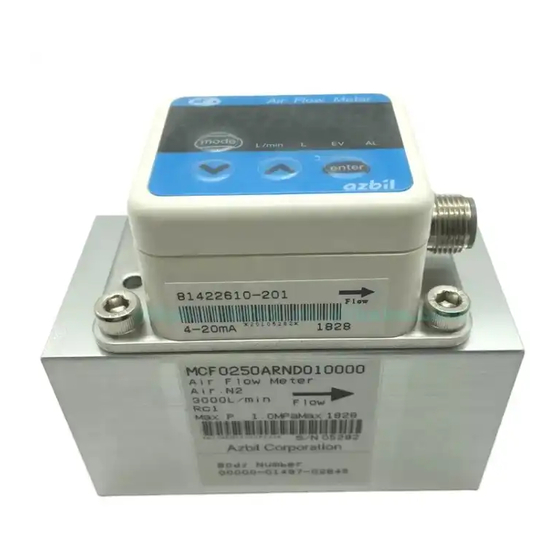
Chapter 2. PART NAMES AND FUNCTIONS ■ Parts name and functions Flow rate display Bolts mode L/min enter Display unit Connector Measurement module Inlet Outlet Main flow path Flow rate display: This 7-segment LED indicates instantaneous flow rate or inte- grated flow amount. -
Page 12: Mounting And Wiring
If damage could result from the abnormal functioning of this device, include appropriate redundancy in the system design. If there is a risk of a power surge caused by lightning, use Azbil Corporation's SurgeNon to prevent possible fire or equipment failure. -
Page 13: Piping
• When attaching the MCF to the pipe, fix the MCF in place and rotate the pipe to the recommended tightening torque. Model Pipe Recommended tightening number size torque [N • MCF0080 1/4 inch 12 to 14 MCF0150 1/2 inch 31 to 33 MCF0151 1/2 inch 31 to 33... - Page 14 Chapter 3. MOUNTING AND WIRING ● MCF _ _ _ _ _ G pipe installation cautions • The MCF is a precision instrument. Do not drop it nor subject it to shock. • Install so that the direction of gas flow matches the arrow on the side of the MCF.
- Page 15 Chapter 3. MOUNTING AND WIRING ● Mounting direction Normally the MCF is mounted on a horizontal pipe with the display unit facing upward. Though the mounting position is unrestricted, measurement error might be caused by the display direction. Normal position on horizontal pipe with display facing upward (Position 1) Flow direction Side view Horizontal pipe with display rotated to the right as seen from air inlet (Position 2)
- Page 16 Chapter 3. MOUNTING AND WIRING • Horizontal pipe with the display facing right as seen from the air inlet (Position 2) Operating pressure range Flow rate range Instantaneous flow rate deviation ± 0 to 1 MPa 5 to 100 % of full scale flow rate 0.5 %FS per 0.1MPa 1 digit or less ±...
- Page 17 If a device that is not listed in the table is installed either upstream or downstream, contact the azbil Group for the length of the straight pipe section. If reverse flow is also expected, it is necessary to have the same length of straight pipe downstream as upstream.
- Page 18 Chapter 3. MOUNTING AND WIRING Note 2: The approximate size of the connection port (D) is 8 mm for the MCF0080 (1/4 inch), 15 mm for the MCF0150/0151 (1/2 inch), 25 mm for the MCF0250 (1 inch), 40 mm for the MCF0400 (1 1/2 inch), and 50 mm for the MCF0500 (2 inch).
- Page 19 However, if the elbow is connected to this device, use the neces- sary straight pipe section for the elbow. Regulator Elbow Straight pipe section (1/4 inch) Distance from this 10D or more device to the regulator: MCF0080 (1/4 inch) 200D or more. For other models, 30D or more.
- Page 20 Chapter 3. MOUNTING AND WIRING • Rotation of display unit The display unit can be rotated 90˚ counterclockwise and 180˚ clock wise from the state of factory shipment (see the figure shown below). counterclockwise clockwise...
-
Page 21: Wiring
Chapter 3. MOUNTING AND WIRING ■ Wiring ● Cautions for wiring • Supply a power voltage within the specified range. • Keep the MCF wiring (conduit) away from power wiring or high voltage wires. • When connecting the connector, push the two parts together, and then tighten the nut by hand to 0.4 to 0.6 N m. - Page 22 Connect terminating resistors of 150 Ω±5%, 1/2 W min. at each end of the transmission line. The FG grounding must not be made at the both shielded wire ends but only at one location. Azbil Corporation ’s CMC10L001A000 can be used as a converter of the host station.
-
Page 23: Functions
Chapter 4. FUNCTIONS ■ Display ● Instantaneous flow rate display and integrated flow display The user can display either instantaneous flow rate or integrated flow total on the 7- segment display. The maximum number of digits displayed for instantaneous flow rate is 5. For the integrated flow, 9 digits are displayed by showing the first 4 digits and the last 5 digits alternately. -
Page 24: Output (4 To 20 Ma Output Models Mcf
Chapter 4. FUNCTIONS ■ Output (4 to 20 mA output models MCF_ _ _ _ _ _ _ D01_ _ _ _ only) The instantaneous flow rate is output as a 4 to 20 mA analog current. The span flow rate (as displayed) can be changed by the parameter setup. -
Page 25: Event Function (Rs-485 Communications Models Mcf
Model Setup [L/pulse] Setup [m /pulse, kg/pulse] Minimum 10 times the 100 times the Minimum 10 times the 100 times the unit minimum unit minimum unit unit minimum unit minimum unit MCF0080 1000 0.01 MCF0150 1000 0.01 MCF0151 1000 0.01... -
Page 26: Operating Pressure Selection
Chapter 4. FUNCTIONS ■ Operating pressure selection By means of the operating pressure setting, the MCF can cancel the effects of pres- sure characteristics by adjusting the output. ■ Reference temperature selection The reference temperature can be set at 1 °C intervals between 0 to 35 °C. The fac- tory setting is 0 °C. -
Page 27: Integration Options For Backflow
Chapter 4. FUNCTIONS ■ Integration options for backflow If there is a reverse flow, the operation of the MCF depends upon the integration option settings, as indicated below. C12 setting Operation 00: Normal and The MCF integrates normal flow and reverse flow separately. reverse flows are integrated Instantaneous flow rate... -
Page 28: Reverse Flow Measurement
● Accuracy Model Flow rate range [L/min] Instantaneous flow rate FS flow rate [L/min] Reverse(upper)/ Normal(lower) display accuracy MCF0080 -60 to -4 ±6 % FS 4 to 200 ±3 % FS ±1 digit MCF0150 -150 to -10 ±6 % FS 10 to 500 ±3 % FS ±1 digit... - Page 29 Chapter 5. SETTING AND OPERATION ■ State transitions [mode] key 2 s or more Maintenance mode [mode] Power ON 2 s or more [mode] key [mode] key 2 s or more 2 s or more Function setup Parameter setup mode mode Instantaneous flow [mode] key...
- Page 30 Chapter 5. SETTING AND OPERATION ■ Function setup ● Setup method (1) Push and hold the [mode] key for 2 seconds or more in the normal indication mode. >> The function number is displayed in the first 3 digits and the current setting is displayed in the last 2 digits.
- Page 31 Chapter 5. SETTING AND OPERATION Func Name Settings Factory Description setting C03 Event output 00: Not used Reversed output is high when the event is OFF 01: Instantaneous flow rate and low when the event is ON. upper limit To cancel the event output for integrated flow 02: Instantaneous flow rate count-up or countdown, reset the count or lower limit...
- Page 32 2. Does not function on RS-485 communications models. 3. Cannot be selected for RS-485 communications models. 4. Can be selected for RS-485 communications models only. 5. Minimum unit MCF0080/0150/0151/0250: 10 L/pulse (0.01 m /pulse, 0.01 kg/pulse) MCF0400/0500: 100 L/pulse (0.1 m /pulse, 0.1 kg/pulse)
- Page 33 Chapter 5. SETTING AND OPERATION ■ Parameter setup ● Setup method (1) Push and hold the [mode] key 2 seconds or more in the normal indication mode. The device enters function setup mode. Again press and hold the [mode] key 2 seconds or more.
- Page 34 AO.20 Flow rate assignment for 20 mA 0 to 400 %FS Depends • No decimal point is displayed on RS-485 analog output equiv. on model communications models. number • Factory settings are shown below. → MCF0080 → MCF0150 → MCF0151 1000 → MCF0250 3000 →...
- Page 35 Chapter 5. SETTING AND OPERATION *1.Analog output scaling (4 to 20 mA output models MCF_ _ _ _ _ _ _ D01_ _ _ _ only) The output current for the instantaneous flow rate is calculated as follows: (Indicated flow rate – 4 mA flow rate) ✕...
- Page 36 Chapter 5. SETTING AND OPERATION setting Low flow rate High flow rate ON (OFF) OFF (ON) Parenthesis indicate the state for reversed output hysteresis (3) When C03 is set to 03 or 06 (within range for instantaneous flow rate) When E1.SP > E2.SP, the setting for E1.SP is used as the upper limit and the setting for E2.SP is used as the lower limit.
- Page 37 Chapter 5. SETTING AND OPERATION C02setting MCF0080 MCF0150 MCF0151 MCF0250 MCF0400 MCF0500 Notes The upper limit 00: [L/min] 0 to 800 0 to 2000 0 to 4000 0 to 12000 0 to 24000 0 to 48000 of the range 01: [m 0 to 48.0...
- Page 38 Chapter 5. SETTING AND OPERATION ■ Other indications ● Instantaneous flow rate peak value (1) Press and hold [ ] for 2 seconds or more in the normal indication mode. >> The MCF moves to instantaneous flow rate peak value display mode, and indicates “FlOHI”...
- Page 39 Flow path identifier 1* 0 to 32768 ✽✽✽✽✽ main flow path. OP.2 Flow path identifier 2* 0 to 32768 Not available on the MCF0080, MCF0150 and MCF0151. ✽✽ SYS0 1 Model number* 2=MCF0250 Can be set for a spare measurement module.
- Page 40 Chapter 5. SETTING AND OPERATION *2: Input the model number and identifier of the replacement measurement module using the following procedure: (1) For SYS0 1, select the model number appropriate for the pipe size of the main path. SYS0 1 setting Model number Pipe size MCF0250 MCF0400...
- Page 41 Be sure to confirm that the MCF is operating normally by inspecting it periodically once or more per year. The MCF has a self-diagnosis function. If an alarm code does not disappear after taking countermeasures, contact the azbil Group or your dealer. Repair or replacement might be necessary.
- Page 42 Chapter 6. MAINTENANCE AND TROUBLESHOOTING ● Maintaining the measurement module Required items: Allen wrench (M5), Air blower, protective goggles, helmet, gloves. Handling Precautions • For your safety, wear goggles while taking the measurement module off. (1) Release the air pressure from the MCF and pipes, and then make sure that the gauge pressure is zero.
- Page 43 If so, clean it. • Check if foreign substances such as dust or oil are present on the pipe or the connection port of the MCF. If so, ask Azbil Corporation for repair. • Check that the wiring is correct.
- Page 44 Chapter 6. MAINTENANCE AND TROUBLESHOOTING ● Alarm codes and remedies Alarm Item Contents Causes Remedy code AL40 Flow rate range Flow exceeds the A forward or reverse Check for excessive flow. If a minus sign is exceeded upper limit for flow exceeds the shown on the flow rate display when the indication.
- Page 45 • Flow rate value: Converted to 0 °C, 101.325 kPa (abs) • Settings: Factory defaults • Warm-up time: 30 minutes after power on Item MCF0080 MCF0150 MCF0151 MCF0250 MCF0400 MCF0500 Measured gas Air, N2. Gas must be dry and not contain corrosive components such as chlorine, sulfur and acid.
- Page 46 Chapter 7. SPECIFICATIONS Item MCF0080 MCF0150 MCF0151 MCF0250 MCF0400 MCF0500 Operating pressure range -0.07 to +1.0 MPa (gauge pressure) Operating temperature range -10 to +60 °C (without freezing) Operating humidity range 0 to 90 % RH (without condensation) Storage temperature range -20 to +70 °C (without freezing)
- Page 47 Chapter 7. SPECIFICATIONS ● Material and treatments Model number MCF_ _ _ _A_ _ _ _ _ _ _ _ _ MCF_ _ _ _F_ _ _ _ _ _ _ _ _ (1) Main flow path Aluminum alloy Aluminum alloy (alumite (alumite treatment) treatment, ultrasonic cleaning, immersed in...
- Page 48 Chapter 7. SPECIFICATIONS ■ External dimensions ● MCF0080 Unit : mm (90) (78) MCF cable connector mode L/min enter Mounting bracket (4.5) Connector (M12) 23.5 Connection type and size 2-Rc1/4 or 2-G1/4 (thread depth: 11) 2-M4 ,Thread depth 7 (Retaining screws) ●...
- Page 49 Chapter 7. SPECIFICATIONS ● MCF0250 Unit : mm (90) (78) MCF cable connector mode L/min enter Mounting bracket (4.5) Connector (M12) 23.5 Connection type and size 2-Rc1 or 2-G1 (thread depth: 19.1) 2-M4 ,Thread depth 7 (Retaining screws) ● MCF0400 MCF cable connector mode L/min...
- Page 50 Chapter 7. SPECIFICATIONS ● MCF0500 Unit : mm MCF cable connector mode L/min enter Connector (M12) 37.5 30.5 Connection type and size 2-M5 ,Thread depth 7 2-Rc2 or 2-G2 (thread depth: 25.7) (Retaining screws)
- Page 51 Typical characteristics are shown below. Characteristics for 0-100 %FS flow rate are shown on the left and characteristics for 100-200 %FS flow rate are shown on the right. ● MCF0080 (1/4 inch) 0-100 % FS flow rate 100-200 % FS flow rate...
- Page 52 Chapter 7. SPECIFICATIONS ● MCF0250 (1 inch) 0-100 % FS flow rate 100-200 % FS flow rate Primary pressure 100kPa Primary pressure 100kPa 300kPa 300kPa 500kPa 500kPa 700kPa 700kPa 1000 1500 2000 2500 3000 1000 2000 3000 4000 5000 6000 Flow rate [L/min] Flow rate [L/min] ●...
- Page 53 Revision History Printed Manual Number Edition Revised pages Description date CP-SP-1276E 1st Edition Dec. 2008 2nd Edition Overall revision June 2009 3rd Edition 2 Model selection guide and Measurement module Nov. 2009 section of Optional parts were changed. MCF_ _ _ _ _R pipe installation cautions were changed.
- Page 54 Azbil Corporation's products. 2. Ascertainment of suitability You are required to ascertain the suitability of Azbil Corporation's products in case of your use of the same with your machinery, equipment, etc. (hereinafter referred to as "Equipment") on your own responsibility, taking the following matters into consideration: (1) Regulations and standards or laws that your Equipment is to comply with.
- Page 55 Although acceleration of the above situation varies depending on the conditions or environment of use of the products, you are required not to use any Azbil Corporation's products for a period exceeding ten (10) years unless otherwise stated in specifications or instruction manuals.
- Page 56 Specifications are subject to change without notice. (09) 1-12-2 Kawana, Fujisawa Kanagawa 251-8522 Japan URL: http://www.azbil.com 1st edition: Dec. 2008 (M) 4th edition: Apr. 2012 (M)
Need help?
Do you have a question about the MCF0080 and is the answer not in the manual?
Questions and answers