
Related Manuals for Azbil MagneW Two-wire PLUS+ MTG15A


Summary of Contents for Azbil MagneW Two-wire PLUS+ MTG15A
- Page 1 CM2-MTG400-2001 MagneW Two-wire PLUS+ Two-wire Electromagnetic Flowmeter TIIS/KCs Explosion-protected Apparatus Model MTG15A User's Manual...
- Page 2 In no event shall Azbil Corporation be liable to anyone for any indirect, special or consequential damages. This information and specifications in this document are subject to change without notice.
-
Page 3: Handling Precautions
Safety Precautions for Use For safe use of the product, the following symbols are used in this manual. Warnings are indicated when mishandling the product might WARNING result in the death or serious injury of the user. Cautions are indicated when mishandling the product might CAUTION result in minor injury to the user or damage to property. -
Page 4: Wiring Precautions
CAUTION After installation, do not step or stand on this unit. Doing so may damage the device or cause injury. Bumping the glass of the display with a tool may cause damage or injury. Be careful. Install the device correctly. Incorrect or incomplete installation will cause output errors and violation of regulations. -
Page 5: Table Of Contents
Table of Contents Chapter 1. Measuring configuration system and model MTG structure ...1-1 1-1. System configuration ..............1-2 1-2. - Page 6 5-6. Configuration of ENGINEERING MODE ..........5-35 5-6-1.
- Page 7 7-3. Calibrating and Inspecting the device by HART Communicator and other functions ..7-25 7-3-1. Device adjustment ............7-25 7-3-2.
-
Page 9: Chapter 1. Measuring Configuration System And Model Mtg Structure
Chapter 1. Measuring configuration system and model MTG structure Outline of this chapter This chapter presents the equipment configuration of a measuring system using this instrument. It also describes the structure and the names and functions of various parts of the main unit. -
Page 10: System Configuration
1-1. System configuration Measuring system Introduction This instrument is a two-wire electromagnetic flowmeter operated on 4-20mA DC. It measures the flow rate of conductive fluid flowing in the detector and outputs a signal that is suitable for the measuring range. Concept of flow rate measurement by this instrument The concept of a flow rate measuring system using this instrument is shown. - Page 11 System configuration 1 for analog output System configuration An example of system configuration is shown. The instantaneous flow rate values measured by this instrument are outputted as a 4-20mA DC analog signal. In this system configuration, the analog signal from the instrument can be outputted directly to a host control system.
- Page 12 System configuration for digital output (DE output) System configuration In the system configuration shown below, the flow rate measurements, database and self- diagnosis results of this instrument are outputted on the DE (digital enhancement) protocol, which is a communication protocol for digital signals. In this system configuration, the instrument transmits digital signals on the DE protocol and the smart protocol converter (SPC) converts the digital signals into analog signals, which is outputted to a control system.
- Page 13 System configuration for pulse output System configuration An example of system configuration is shown. Instantaneous flow rate values measured by this instrument are outputted as a pulse output with the specified pulse width and pulse weight. Besides an analog signal, this system configuration allows the instrument to output a pulse output to an electronic counter, sequencer or other host control system or counter.
- Page 14 System configuration for contact output System configuration An example of system configuration is shown. If the instantaneous flow rate value measured by this instrument reaches to the upper or lower limit settings or a major failure occurs in the instrument, that state is outputted as a contact output. In this system configuration, it is not only an analog signal but also the instrument to output the contact output to a sequencer or other host control system.
-
Page 15: Tiis/Kosha Explosion-Protected Apparatus
1-2. TIIS/KOSHA Explosion-protected apparatus Before use This is flameproof structure flowmeter. Read this item carefully to ensure correct use. Flameproof structure Flameproof structure means a totally enclosed housing that is capable of withstanding an explosion of a gas or vapor within it, and of preventing the ignition of an explosive gas or vapor that may surround it. - Page 16 Certificate number (TIIS/KOSHA) Flange Flange Wafer Wafer Line size (Pipe material: (Pipe material: (Pipe material: (Pipe material: [mm] SCS14) SUS304) SCS14) SUS304) TC19022 12-AV4BO-0368 TC19022 12-AV4BO-0368 TC19022 12-AV4BO-0368 TC19022 12-AV4BO-0368 TC19028 TC19023 TC19028 12-AV4BO-0377 12-AV4BO-0369 12-AV4BO-0377 TC19029 TC19024 TC19029 12-AV4BO-0378 12-AV4BO-0370 12-AV4BO-0378 TC19031...
-
Page 17: Structure Of This Instrument And Functions Of Its Various Parts
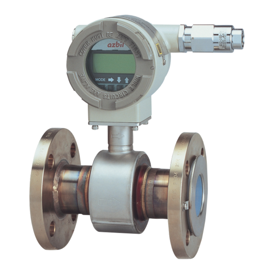
1-3. Structure of this instrument and functions of its various parts Structure of main unit Major components This instrument consists of a detector and converter. The converter, consists of the converter proper, indicator/data setter and terminal box. Fig. 1-7. shows overview of the instrument. (The detail specification and outline drawing, refer to SS2-MTG100-0100) Set screw Converter... - Page 18 Detector 1: Flanged type Description The flanged detector has the function and structure as follows: When a fluid passes through the inside, the detector generates a signal of electromotive force, which is proportional to the passing flow rate. Installs to the pipes and supports the entire instrument. ...
- Page 19 Detector 2: Wafer type Description The wafer type detector has a function and structure as follows: When a fluid passes through the inside, the detector generates a signal of electromotive force that is proportional to the passing flow rate. ...
- Page 20 Indicator / data setter Description The indicator/data setter has the following function and structure. Displays the instantaneous flow rate value and internal conditions of the instrument. The indicator face can be turned at intervals of 90 degrees through one turn. Names of various parts The names of various parts of the indicator/data setter are shown.
- Page 21 Names and description of various parts The following table describes the various parts of the terminal box. Name Description Terminal box „ Watertight construction (equivalent to NEMA 4X) cover Wiring „ Matters to pay attention to when doing wiring work of this instrument precautions are given.
- Page 22 1-14...
-
Page 23: Chapter 2. Installing The Model Mtg
Chapter 2. Installing the model MTG Outline of this chapter This chapter describes the installation and wiring of the instrument. The necessary components and installing methods depend on the grounding ring material and installed pipe material. The description proceeds in the following order: ... -
Page 24: Before Installation
2-1. Before installation Criteria (1) for installation location Introduction To bring out the performance of this instrument to the maximum, choose the optimum installation location according to the following criteria for installation location. Cautions on surrounding environment Install at a place where the ambient temperature is in the range from -4°F to +140°F (-20°C to +60°C) and ambient humidity in the range from 10 to 90% RH. - Page 25 Caution On PLC Connection A circuit in some PLC may affect the flow measurement and the analog output may fluctuate. In this case, make sure that the both PLC and the MTG flowmeter are properly grounded. Proper grounding solves the fluctuation problem. Cautions after installation CAUTION (1) Avoid using this instrument as a foothold after installation because such a use may cause...
- Page 26 Criteria (2) for installation location Installed position Install the instrument at a place where the measured fluid always fills inside the detector. An example of installation is shown in the figure below to illustrate this condition. Prone to stagnation of air The fluid The fluid Good...
- Page 27 No straight pipe section is basically needed on the downstream side. However, ensure 2D or over if influences of drift are foreseen. Choose a place where there are little pulsations in the flow (install at a place sufficiently distant from a pump or the like).
- Page 28 Direction of display/data setter Changing the display / data setter direction The display / data setter can be changed to a horizontal or vertical direction. Step Procedure Power-off the converter. For the power-off, use the circuit breaker or the like. The converter front cover is fixed by hexagon socket head setscrews (M3).
-
Page 29: Method Of Installation
2-2. Method of Installation 2-2-1. Installing a safer type detector Basic installation method Introduction Process connection of the instrument are wafer type, flange type, union, hose, or clamp unit. Referring to the appropriate method of installation, install the unit properly. Installation example Fig. - Page 30 Table. 2-1. Fastening torque Diameter and flange ratings Fastening torque N•m (kgf•cm)* JIS 10K 21 to 31 (214 to 316)* 25 mm JIS 20K 21 to 32 (214 to 326)* (1 inch) ANSI/JPI 150 11 to 17 (112 to 173)* ANSI/JPI 300 22 to 34 (224 to 347)*...
- Page 31 Flange shape The flanges used should be such that the area of contact with the gasket is maximized, as shown in Fig. 2-6. Acceptable X Unacceptable Flange (The liquid could leak because of Welding Welding the small area of contact with the gasket.) Pipe Fig.
- Page 32 CAUTION Before installing the detector make sure that the pipe is exactly straight and centered. Any irregularity in these respects could cause leakage or other hazards. Tilted pipe Off center Fig. 2-7. Examples of unacceptable installations (1) Note) Never force the device between two flanges when the space is too narrow. It can damage the detector.
- Page 33 Accessory parts for installation Introduction The following parts are necessary for the installation of the detector: Centering guide bushing (standard accessory) Through bolts and nuts (option) Gaskets: Provide gaskets by customer when using grounding rings made of SUS material.
- Page 34 Gaskets Gaskets are supplied with the grounding ring as standard accessory, except when it is made of SUS material. Secure gaskets when you use a grounding ring made of SUS material. We recommend gasket material such as joint sheet or PTFE. For the internal diameters of the gaskets, refer to Table 2-2 We do not recommend the use of rubber gaskets.
- Page 35 Selecting an installation method CAUTION The necessary materials and the installation method vary according to the material of the ring and that of the pipe on which the detector is to be installed. Select the appropriate method of installation after confirming the specifications of the detector to be installed and the conditions of installation.
- Page 36 Installation on horizontal pipe CAUTION Improper installation may result in leakage or damage to the pipe flanges. Required accessories The following parts are required: Through-bolts and nuts Centering guide bushing Gaskets: The required gasket material will vary according to the material of the pipe on which the detector is to be installed.
- Page 37 Installation on vertical pipe CAUTION Improper installation may result in leakage or damage to the pipe flanges. Required accessories The following parts are required: Through-bolts and nuts Centering guide bushings Gaskets: The required gasket material will vary according to the material of the pipe on which the detector is to be installed.
- Page 38 Step Action Drawing „ Insert through-bolts fitted with one centering nut each into the remaining two flange holes shown by black dots in steps 1 and 2. „ Make sure that the detector remains properly centered. „ Make sure that the gaskets do not protrude beyond the edges of the pipe flanges.
- Page 39 Installation on metal pipe (1) Introduction The installation method described in this section corresponds to the following combination of pipe and grounding ring materials. For the installation method corresponding to any other combination, refer to the table on page 2-13. Pipe material: Metal Grounding ring material: SUS material Required accessories...
- Page 40 Installation on metal pipe (2) Introduction The installation method described in this section corresponds to the following combination of pipe and grounding ring materials. For the installation method corresponding to any other combination, refer to the table on page 2-13. Pipe material: metal Grounding ring material: other than SUS material Required accessories...
- Page 41 Installation on PVC pipe (1) Introduction The installation method described in this section corresponds to the following combination of pipe and grounding ring materials. For the installation method corresponding to any other combination, refer to the table on page 2-13. Pipe material: PVC Grounding ring material: SUS material Required accessories...
- Page 42 2. Use this method to install the detector using a protective plate to prevent the PVC pipe from being deformed or damaged when the bolts are tightened with the specified torque. Install the protective plate between the outer side of the PVC flange and the detector, as shown in Fig.
- Page 43 Installation on PVC pipe (2) Introduction The installation method described in this section corresponds to the following combination of pipe and grounding ring materials. For the installation method corresponding to any other combination, refer to the table on page 2-13. Pipe material: PVC Grounding ring material: Other than SUS material Required accessories...
- Page 44 2. Use this method to install the detector along with a protective plate to prevent PVC pipe from being deformed or damaged when the bolts are tightened to the specified torque. Insert a protective plate between the outer side of the PVC flange and the detector as shown in Fig.
-
Page 45: Installation A Flange Type Detector
2-2-1. Installation a flange type detector Basic installation method Installation example Fig. 2-20 shows the basic method for installing the device. Nuts Through-bolts Pipe Gasket (Required when the grounding ring is made of SUS material. In other cases, the gasket is supplied.) Fig. - Page 46 Table. 2-5. Fastening torque (1) Diameter and flange ratings Fastening torque N•m (ft•lb) JIS 10K 8 to 13 (5.9 to 9.5) JIS 20K 8 to 13 (5.9 to 9.5) 2.5 to 15 mm ANSI/JPI 150 9 to 14 (6.6 to 10.3) ANSI/JPI 300 10 to 16 (7.3 to 11.8)
- Page 47 Flange shape Use flanges that will maximize the area of contact with the gasket, as shown in Fig. 2-21. Acceptable Acceptable (The liquid could leak out because Welding of the small area of contact with the gasket. Flange Pipe Fig. 2-21. Flange shape Note) Before installing the detector, make sure any foreign matter is flushed from the inside of the detector.
- Page 48 Accessory parts for installation Introduction The following parts are necessary for the installation of the detector: Gaskets: Provides gaskets by customer when using grounding rings made of SUS material. Supplied gaskets as standard accessory, when using grounding rings made of other material.
- Page 49 Selecting an installation method Caution CAUTION The necessary materials and the method of installation vary depending on the material of the grounding ring and the material. Select the applicable method of installation after checking the specifications of the detector to be installed and the conditions of installation. Improper installation may result in leakage or damage to the pipe flanges.
- Page 50 Installation on metal pipe (1) Introduction The installation method described in this section is to be used with the following grounding ring materials. For the installation method used for any other grounding ring material, refer to the table on page 2-27. Pipe material: Metal Grounding ring material: SUS material Required accessories...
- Page 51 Installation on metal pipe (2) Introduction The installation method described in this section is to be used with the following grounding ring materials. For the installation method used with grounding rings of SUS material, refer to the table on page 2-27. Pipe material: metal Grounding ring material: other than SUS material Required accessories...
- Page 52 Installation on PVC pipe (1) Introduction The installation method described in this section is used for the following combination of pipe and grounding ring materials. For the installation method corresponding to any other combination, refer to the table on page 2-27. Pipe material: PVC Grounding ring material: SUS material Required parts...
- Page 53 2. Use this method to install the detector using a protective plate to prevent PVC pipe from being deformed or damaged when the bolts are tightened to the specified torque. Install the protective plate between the outer side of the PVC flange and the detector, as shown in Fig.
- Page 54 Installation on PVC pipe (2) Introduction The installation method described in this section is to be used for the following combination of pipe and grounding ring materials. For the installation method used for any other combination, refer to the table on page 2-27. Pipe material: PVC Grounding ring material: Other than SUS material Required parts...
- Page 55 2. Use this method to install the detector along with a protective plate to prevent PVC pipe from being deformed or damaged when the bolts are tightened to the specified torque. Insert a protective plate between the outer side of the PVC flange and the detector as shown in Fig.
- Page 56 2-34...
-
Page 57: Chapter 3. Electrical Wiring
Chapter 3. Electrical wiring Outline of this chapter This chapter describes the electrical wiring of the main unit, SFC and HART® Communicator. -
Page 58: Electrical Wiring
3-1. Electrical wiring Electrical wiring Introduction For this instrument to operate, 15.6 to 42 V DC power supply is required to signals wiring. The electrical wiring of this instrument is described below as to the following items: Wiring cable connecting positions ... - Page 59 For a sequencer or other application that does Load analog/digital conversion of 4-20 mA at high resistance Receiving speed, use it after adding the following circuit 1µF instrument in parallel with the load resistance. Selecting the wiring cable For the electrical cable, we recommend 600 V vinyl insulation, vinyl sheath wire CVV with a conductor area of 2 mm or a stranded wire cable having equivalent or superior performance.
- Page 60 Fig. 3-2.
- Page 61 Grounding (integral type) For the grounding terminal, do grounding work (grounding resistance 100 Ω or less) according to Fig. 3-3. or Fig. 3-4. Do not ground both at the same time. Hazardous area Non-hazardous area Grounding resistance 10 Ω or less Grounding at non-hazardous area Fig.
- Page 62 Hazardous area Non-hazardous area Status output or pulse output Flameproof receiver cable gland Pulse output Status output General 2-core Flameproof (Intrinsically equipment shielded cable cable gland safe circuit) Power supply / Output Hazardous area Non-hazardous area Status output or pulse output Flameproof receiver cable gland...
- Page 63 Wiring connection of power supply and analog current output Hazardous area Non-hazardous area ® HART Communicator Power supply 24 V / 42 V DC – – Receiving Converter instrument Black – Fig. 3-6. Wire connection diagram CAUTION „ Incorrect wiring polarity can do damage to the equipment. Double-check the wiring position.
- Page 64 Wiring connection for contact output Because of an open-collector output, do wiring paying attention to the polarity. Hazardous area Non-hazardous area Protective diode 100mA max. STATUS OUT + Load – STATUS OUT – – Avoid this polarity External power source 30 V DC max.
- Page 65 Wiring procedure Do wiring between the instrument and a power supply according to the following procedure. Step Procedure The terminal box cover is fixed by hexagon socket head setscrews (M3). Loosen the setscrews with an Allen wrench (1.5). Remove the terminal box cover by turning it counterclockwise with the dedicated tool.
- Page 66 3-10...
-
Page 67: Chapter 4. Start And Stop Operation Procedure For Model Mtg
Chapter 4. Start and stop operation procedure for model Outline of this chapter This chapter describes the procedure to start the instrument and do zero adjustment. When starting and operating the instrument for the first time, follow the descriptions in this chapter. -
Page 68: Confirmation Before Start
4-1. Confirmation before start Introduction Before you start up the instrument, confirm the following items. Numbers in parentheses indicate the chapter to which to refer. (1) Confirm that the electromagnetic flowmeter is installed correctly in the pipes (Chapter 3. Electrical wiring). (2) Confirm that the electrical wiring is correct (Chapter 3. -
Page 69: Stopping
4-2. Stopping Note) When stopping the instrument from operation and shutting down the output to control equipment, always change over the control equipment to manual control. This is for preventing the instrument's output shutdown from directly influencing the control equipment. When the following operations are performed, new or changed data are saved in nonvolatile memory. -
Page 71: Chapter 5. Operation Using The Data Setting Device
Chapter 5. Operation using the data setting device This section describes how to operate this system from the data setting device. This system configuration and settings can be made using the four keys on the data setting device. -
Page 72: Startup
5-1. Startup Introduction With the model MTG, all settings can be configured from the data setting unit. Startup When the power supply is turned on, the display changes in the order of OVERALL DISPLAY, SELF CHECK MODE, and MEASURING MODE. OVERALL DISPLAY 8.8.8.8.8.8.8.8 Main display: 7-segment, 8-digit display... - Page 73 Display and operation contents of data setting device Overview of mode This system provides the following four modes available in accordance with the operations: Mode Description MEASURING MODE Mode that shows measuring status. OPERATOR’S MODE Mode that is set for the operator. This mode is comprised of setting and configuration of data that are set or changed frequently during startup.
- Page 74 Mode Description MAINTENANCE MODE A mode for maintenance that is used when adjustments and checks are needed for regular maintenance and when troubles occur. Adjustments and checks are allowed only at write protect level 0. [Loop check, output adjustment, gain adjustment, etc.] This mode is furthermore divided into the following three types: OUTPUT CHECK MODE...
-
Page 75: Functions Of The Data Setting Device
5-2. Functions of the data setting device 5-2-1. Data setting device Name of parts Totalizer display mark 7-segment 8-digit display Main display % flow rate display mark Sub display Actual flow rate display mark Increment key Mode key Decrement key Right shift key Names and Descriptions of Parts This section describes displays shown on the data setting device. - Page 76 This section describes keys on the data setting device. Name Description MODE key „ Enters OPERATOR'S MODE. „ When parameters and configured data have been changed in ENGINEERING MODE or MAINTENANCE MODE, press this key to save the data. Right shift key „...
-
Page 77: Description Of Measuring Mode
5-3. Description of MEASURING MODE 5-3-1. Display overview % flow rate display 1st line ( Main display): 7-segment 4-digit display % flow rate (%) 2nd line: Actual flow rate display (Significant value of 1 0 0. 0 5 digits) 3rd line: Totalized value display (Significant figure of 8 7 . -
Page 78: Display Of Write Protect Level
5-3-2. Display of write protect level Protect level The write protect levels and their corresponding settings and operating condition are shown below. LSC (Key operation) Communication Write protect level ENABLE ENABLE ENABLE ENABLE ENABLE ENABLE ENABLE ENABLE ENABLE ONLY ONLY ONLY ENABLE ONLY... - Page 79 Settings of write protect switches SW No. At shipment Determined by WP LEVEL. Determined by WP LEVEL. ON (No data change is allowed.) Main board...
-
Page 80: Overview Of Operation Using The Data Setting Device
5-4. Overview of operation using the data setting device Introduction The data setting device has three types of modes: OPERATOR'S MODE, ENGINEERING MODE, and MAINTENANCE MODE. MAINTENANCE MODE is furthermore divided into three of sub-modes: OUTPUT, CALIBRATION, and CRITICAL. The screen flow is as follows: Entire display flow 1 O U T P U T C H E C K W / C A L I B R A T O R... -
Page 81: Configuration Of Operator's Mode
5-5. Configuration of OPERATOR'S MODE Introduction OPERATOR'S MODE provides the following setting and adjustment items. For details on functions in the items, see “5-5-1. Changing setting of damping time constant” and later. Item Contents Screen DAMPING Sets a damping time constant. 20.0 % * DAMPING 005.0 s... - Page 82 LCD display flow The LCD display flow of the OPERATOR'S MODE is as shown below: * OPERATOR'S MODE * DAMPING 003.0 s * AUTO ZERO READY * CNT-RESET VALUE 00000000 * CNT-RESET READY PREV 00000000 * SPIKE CUT * AVERAGING 30.0 s * ELECTRODE_ST SENSITIVITY...
-
Page 83: Changing Setting Of Damping Time Constant
5-5-1. Changing setting of damping time constant Damping means a response time of the primary time lag (63.2% response) for a step response of the flow rate. If the out fluctuations are large, increase the damping. A large damping value stabilizes the output but lowers the response performance. -
Page 84: Auto Zero Adjustment
5-5-2. Auto zero adjustment Auto zero must be carried out only under the condition when the detector is filled with process fluid at zero flow. Run this function only after installing the electromagnetic flowmeter to the process pipe. Performing this function under a condition where the process fluid is not at zero flow may cause measurement errors. -
Page 85: Setting Of Built-In Counter Reset Value
5-5-3. Setting of built-in counter reset value Set a start value of the built-in counter. The scale of this value is considered as the weight of the pulse. Carry out the built-in counter reset in section 5.4.5 to start totalization from any totalized value. - Page 86 5-5-4. Setting of built-in counter reset value Reset the built-in counter to start totalization from a value set as the built-in counter reset value. If this value is set to 1000, the built-in counter starts totalization from 1000 after the counter is completely reset.
-
Page 87: Setting Auto Spike Cut
5-5-5. Setting auto spike cut This function eliminates steep noise spikes (spike noise) in the flow rate. Noise generated when foreign matters collide with electrode is an example of the spike noise. When the flow rate changes sharply, this function holds the outputs according to the damping time. Generally the spike noise occurs in a few milliseconds and settles down within the output holding time and the outputs are not affected. -
Page 88: Setting Moving Average Processing
5-5-6. Setting moving average processing This function is used to carry out the moving average processing of the measured flow rate values. The model MTG performs the flow rate calculation every 400 ms. For example, if the moving average process time is set to 2 seconds, the moving average processing will be carried out 2 sec. - Page 89 Set the moving average processing in accordance with the following procedure: Step Procedure Screen The screen at right is a screen display example in 20.0 % MEASURING MODE (measurement state). Press the 01.94 m MODE key. 00069401 The OPERATOR'S MODE screen appears for approx. 20.0 % two seconds and then the damping setting screen * OPERATOR'S...
-
Page 90: Setting Electrode Status Diagnostic Function
5-5-7. Setting Electrode Status Diagnostic function Overview of electrode status diagnostic function Electrode status diagnostic function detects the condition of the empty pipe or the scale on the electrodes. The Electrode status diagnostic function makes the analog output and pulse output to the values as selected in the below “Electrode status output mode”... - Page 91 Mechanism of electrode status diagnostic function Detect empty pipe condition or scale on electrode condition by monitoring flow rate signal. Once the flow rate signal fluctuates over a certain threshold, the device judges that the flowtube is empty or scale appears on the electrodes. There are five threshold levels to meet an environment where the device is installed.
-
Page 92: Setting Parameters
Operation conditions The grounding work must be securely carried out (grounding resistance 100 Ω or less). The fluid conductivity must be 30 µS/cm or greater. The noise level must be higher than or equal to the set threshold value when the pipe is empty. - Page 93 Set the electrode status diagnostic function in accordance with the following procedure. Step Procedure Screen The screen at right is a screen display example in 20.0 % MEASURING MODE (measurement state). 01.94 m 00069401 Press the MODE key. 20.0 % The OPERATOR'S MODE screen appears for approx.
- Page 94 Step Procedure Screen Repeat steps 1 to 5 to set SENSITIVITY MID or SENSITIVITY LOW, SENSITIVITY LL or SENSITIVITY LLL to check if the function also detects the empty or scale on electrode status with the converter's display. Depending on whether the empty status is detected in each setting, the result falls into one of the following.
- Page 95 Step Procedure Screen Next, fill fluid into the pipe. If the scale appears on the electrodes, clean the electrodes and fill fluid. Check that the empty or scale on electrode status is not detected in this condition. Since it takes at least 30 seconds to clear the empty or scale on electrode status after fluid is filled in the pipe, perform checking when 30 seconds or more have passed after fluid is filled.
- Page 96 Step Procedure Screen (Branch 4) „ When the result is (4) in Step 8 (Continued) Check that the empty or scale on electrode status is not detected when SENSITIVITY MID has been set. (Result) „ If the empty or scale on electrode status is not detected, use that SENSITIVITY MID setting without change.
- Page 97 Electrode status diagnostic flow chart Install the MTG 2 to the pipe. Pipe should be empty Electrode Status Diagnostic function Default setting: SENSITIVITY OFF Change the SENSITIVITY to HIGH when the pipe is empty or the scale appears on electrode. Blink Electrode Status Diagnostic function is not applicable.
- Page 98 Electrode status diagnostic troubleshooting Troubleshooting If a problem occurs during electrode status diagnostic, take appropriate actions in accordance with the following procedure. Trouble Check point and troubleshooting „ Electrode status diagnostic When the flow rate swiftly changes due to pulsations mistake when fluid is filled from the pump, the function may recognize some of the because the unit is used in the...
- Page 99 Selecting the Electrode Status Output Mode Setting the output mode when the Electrode Status Diagnostic function detects the empty or scale on electrode status. There are the following three electrode status output modes. OFF ZERO HOLD Default setting: OFF Detailes of the “Electrode Status Output mode”...
- Page 100 Set the Electrode status output mode in accordance with the following procedures. Step Procedure Screen The screen at right is a screen display example in 20.0 % MEASURING MODE (measurement state). 1.94 m3/h 00069401 Press the MODE key. 20.0 % The OPERATOR'S MODE screen appears for * OPERATOR'S approximately two seconds, and then the damping...
-
Page 101: Selecting Flow Rate To Be Displayed In The Main Display
5-5-8. Selecting flow rate to be displayed in the main display Select the flow rate to be always shown in the main display. The flow rates other than that selected for the main display are shown in the sub displays. Thereby, three flow rates can always be monitored. -
Page 102: Selecting A Communication System
5-5-9. Selecting a communication system Select the communication system (SFC, DE, HART, and communication disable). Select a communication system to be used. Note that the converter will be rebooted when the MODE key is pressed to switch to the MEASURING MODE after the settings are changed. HART: HART communication by using the HART Communicator. -
Page 103: Entering Engineering Mode And Maintenance Mode
5-5-10. Entering ENGINEERING MODE and MAINTENANCE MODE Introduction This section describes how to enter ENGINEERING MODE, in which setup parameters for the electromagnetic flowmeter are to be configured, and MAINTENANCE MODE, in which calibration and check are to be carried out. Note) The mode selection screen may not appear, depending on the settings of write protect. - Page 104 The procedure for entering MAINTENANCE MODE is shown below. Step Procedure Screen The screen shown on the right is a screen display 20.0 % example in MEASURING MODE (measurement 01.94 m state). 00069401 Press the MODE key. The OPERATOR'S MODE screen appears for approx. 20.0 % two seconds, and then the damping setting screen * OPERATOR'S...
-
Page 105: Configuration Of Engineering Mode
5-6. Configuration of ENGINEERING MODE Introduction ENGINEERING MODE has the following setting and adjustment items: For details on items, see “5-6-1. Setting ID” to “5-6-15. Setting contact output status”. Item Contents Screen ID SET Sets ID and TAG No. 20.0 % # ID SET XXXXXXXX FUNC SET... - Page 106 Item Contents Screen PLS WID Sets the output pulse width. 20.0 % # PLS 10.000 Hz 0010 ms DROP OUT Sets drop out. 20.0 % # DROPOUT 10 % LOW FLOW CUT Sets low flow cut. 20.0 % # LOW FLOW CUT 10 % HI-ALM/LOW-ALM Sets upper/lower limit alarm.
- Page 107 LCD display flow The ENGINEERING MODE display flow is as follows: # ENGINEERING MODE # ID SET XXXXXXXX # FUNC SET PULSE EX 300.0 1.0000 1.0234 1.0000 m/s SPAN 7.0690 m # GRAVITY 1.0000 # COEFFICIENT 1.0000 # PLS 10.000 Hz # HI-ALM 100 % 196.36 m...
-
Page 108: Setting Id
5-6-1. Setting ID You can enter a unique 8-digit alphanumeric code for the flowmeter. Up to eight alphanumeric characters using any combination of letters (A to Z), numbers (0 to 9), - (dash), / (slash), space and period. Set an ID in accordance with the following procedure: Step Procedure Screen... -
Page 109: Selecting Pulse Output, Electrode Status Output Or High Low Status Output
5-6-2. Selecting Pulse Output, Electrode Status Output or High Low Status Output Pulse output, electrode status output or high low status output are selectable. They are open collector outputs. When pulse output has been selected: Set pulse scale, pulse width, drop out, and failsafe mode for the pulse output. When high low status output has been selected: As a contact output, self diagnostic output (critical failure) or upper/lower limit alarm is output. -
Page 110: Setting Detector Information
5-6-3. Setting detector information Set detector information necessary for combination with the converter. EX value: Each detector has a unique calibration factor (EX value). This value is determined at shipment in accordance with the actual flow rate calibration. DO NOT change this value or the flowmeter output will be incorrect. -
Page 111: Setting Detector Factor
5-6-4. Setting detector factor Set the detector factor. The C1 value is always 1.0000. Set the C2 value to that shown on the detector nameplate under the heading Detector Factor. Step Procedure Screen Enter ENGINEERING MODE (see “5-5-10. Entering 20.0 % ENGINEERING MODE and MAINTENANCE _ # C1 1.0000... -
Page 112: Setting Flow Rate Range
5-6-5. Setting flow rate range Set the flow rate range. The lower limit of the range is ZERO. The upper limit, which is the value when the output reaches 100%, is entered here along with the selection of engineering and time units. The range has an upper limit value of 10 m/s in flow velocity when it is calculated at the upper stage of the display. -
Page 113: Setting And Changing Compensation Coefficient
5-6-6. Setting and changing compensation coefficient This function is used to set or change the compensation coefficient which is used to multiply the output flow rate as required. Set range: 0.10000 to 5.9999 Default: 1.0000 Set and change a compensation coefficient in accordance with the following procedure: Step Procedure Screen... -
Page 114: Setting Specific Gravity
5-6-7. Setting specific gravity This function is used to set the specific gravity when selecting a weight unit (t, kg, g, lb) in the flow rate range setting. Set range: 0.1000 to 5.9999 Default: 1.0000 Set the specific gravity in accordance with the following procedure: Step Procedure Screen... -
Page 115: Setting Pulse Scale
5-6-8. Setting pulse scale This function is used to set the flow rate per pulse and associated units for a flowmeter. Pulse scale of the totalization value indicated on the display is equal to the pulse scale set here. Set range: 0.0001 to 99999. However, the pulse scale should be set so that the pulse output span frequency fs (shown in the auxiliary display) is between 0.0001 Hz and 200 Hz. - Page 116 Set pulse scale in accordance with the following procedure: Step Procedure Screen Enter ENGINEERING MODE in accordance with the 12.3 % entry into ENGINEERING MODE (see section 5-5- # PLS 27.780 Hz 10. on page 5-33). Then press the or key to 100.00 l/p display the screen at right.
-
Page 117: Setting Pulse Width
5-6-9. Setting pulse width Set a pulse width. The pulse width should be set in accordance with the specifications of the pulse receiver installed. Set range DUTY 50% Pulse width that is DUTY 50% of the span frequency, and 1,000 ms (1s) maximum. The pulse duty ratio defines the pulse ON time versus the pulse OFF time as a percentage of the total pulse cycle. - Page 118 2. DUTY 50% (Automatically set) Selecting DUTY 50% automatically sets the pulse width as follows: Calculation method 1 Make calculations to obtain a pulse width that is DUTY 50% of the span frequency. The pulse width is automatically set. In this case, the calculated value of the pulse width does not appear on the display.
- Page 119 Set a pulse width in accordance with the following procedure: Step Procedure Screen Enter ENGINEERING MODE in accordance with the 12.3 % entry into ENGINEERING MODE (see section 5-5- # PLS 27.778 % 10. on page 5-33). Then press the or key to WID NUM 010.00ms display the screen at right.
-
Page 120: Setting Drop Out
5-6-10. Setting drop out This function is used to set the drop out value for the pulse output. The pulse output will be cut off at this point to avoid flow pulsation in range values close to zero, thus preventing incorrect totalization of the flow rate. - Page 121 Set drop out in accordance with the following procedure: Step Procedure Screen Enter ENGINEERING MODE in accordance with the 12.3 % entry into ENGINEERING MODE (see section 5-5- # DROPOUT 10. on page 5-33). Then press the or key to 02 % display the screen at right.
-
Page 122: Setting Low Flow Cutoff
5-6-11. Setting low flow cutoff This function is used to set the low flow cutoff value. When the flow rate reaches the entered value, the analog output is cut off and latched to 4 mA (display flow rate of 0%) to avoid errors due to flow pulsation in range value close to zero. -
Page 123: Setting Upper And Lower Limit Alarm
5-6-12. Setting upper and lower limit alarm This function is used to set the upper and lower limit alarm set points when the contact output is selected. An alarm is output when the flow rate exceeds these preset upper and lower limits. The alarm output status depends on the “Setting contact output status”... -
Page 124: Selecting Failsafe Mode For Analog Outputs
5-6-13. Selecting failsafe mode for analog outputs This function is used to determine the analog output direction when the flowmeter detects a critical status condition. CAUTION The failsafe mode is very important for the overall safety of the control process. Choose the failsafe direction carefully, as equipment damage can result from a wrong choice. -
Page 125: Selecting Failsafe Mode For Pulse Output
5-6-14. Selecting failsafe mode for pulse output This function is used to determine the pulse output direction when the flowmeter detects a critical status condition. CAUTION The failsafe mode is very important for the overall safety of the control process. Choose the failsafe direction carefully, as equipment damage can result from a wrong choice. -
Page 126: Setting Contact Output Status
5-6-15. Setting contact output status This function is used to set contact output status for normal operation. This function is effective only when contact output has been selected is the function specification. Set range: CLOSE Sets the open collector output to ON. OPEN Sets the open collector output to OFF. -
Page 127: Configuration Of Maintenance Mode
5-7. Configuration of MAINTENANCE MODE Introduction MAINTENANCE MODE consists of the following three types: OUTPUT CHECK MODE, CALIBRATION MODE, and CRITICAL MODE. For details on the modes, see the following pages. LCD display flow The LCD display flow of MAINTENACE MODE is as follows: >... -
Page 128: Configuration Of Output Check Mode
5-7-1. Configuration of OUTPUT CHECK MODE Introduction OUTPUT CHECK MODE has the following setting and adjustment items. For details on the function of items, see the following pages. Item Content Screen OUTPUT Perform loop checks by using a 20.0 % CHECK calibrator (Model MGZ). - Page 129 LCD display flow The screen flow of OUTPUTCHECK MODE is as follows: > OUTPUT CHECK W/CALIBRATOR > OUTPUT CHECK I.OUT 100% > OUTPUT CHECK P.OUT 100% > OUTPUT CHECK ST.OUT CLOSE > OUTPUT CHECK > OUTPUT CHECK MODE Note) *1. Displayed only when PULSE is selected by FUNC SET in ENGINEERING MODE. *2.
-
Page 130: Performing Loop Checks Of Analog Outputs By Using A Calibrator Model Mgz
5-7-2. Performing Loop Checks of Analog Outputs by using a calibrator Model MGZ. Analog Output Check With the signal input by a calibrator Model MGZ, the electromagnetic flowmeter outputs analog 4 to 20mA to perform the loop check. Other instruments in the analog current output loop, such as recorders and controllers can be checked. -
Page 131: Performing Loop Checks Of Analog Outputs
5-7-3. Performing loop checks of analog outputs Analog output check The electromagnetic flowmeter can be used as a constant current generator to check analog outputs. Other instruments in the analog current output loop, such as recorders and controllers can be checked. Default setting Displays the current output value. -
Page 132: Performing Loop Checks Of Pulse Outputs
5-7-4. Performing loop checks of pulse outputs Pulse output check The electromagnetic flowmeter can be used as a pulse generator to check pulse outputs. This screen appears when pulse output has been selected in FUNC SET of ENGINEERING MODE (see “5-6-2. Selecting Pulse Output, Electrode Status Output or High Low Status Output”). -
Page 133: Performing Loop Checks Of Contact Outputs
5-7-5. Performing loop checks of contact outputs Contact output check Contact outputs of electromagnetic flowmeter can be turned on and off to perform loop checks of contact output signals. This screen appears when contact output has been selected in FUNC SET of ENGINEERING MODE (see “5-6-2. -
Page 134: Configuration Of Calibration Mode
CALIBRATION MODE has the following setting and adjustment items: Configuration of CALIBRATION MODE requires a dedicated calibrator. Wrong operation may hinder accurate measurements of the flow rate. To operate in this mode, contact an Azbil Corp. representative. Item Content Screen CAL EX Adjusts 3.5 mA excitation... - Page 135 Item Content Screen CAL GAIN Adjusts 0 m/s gain. 12.3 % ZERO > CAL GAIN OFF ZERO READY CAL GAIN Adjusts 2.5 m/s gain. 12.3 % 2.5 m/s > CAL GAIN OFF 2.5 m/s READY CAL GAIN Adjusts 10.0 m/s gain. 12.3 % 10.0 m/s >...
- Page 136 LCD display flow The LCD display flow of CALIBRATION MODE is as follows: > CAL EX 3.5 mA > CAL EX 4.9 mA > CAL EX 7.0 mA > CAL EX 11.9 mA > CAL EX 14.0 mA > CAL I. OUT 4.000 mA >...
-
Page 137: Manual Zero
5-7-7. Manual zero This function is used to improve flow measurement more accurately when the flow rate becomes 25% or less of setting range. Model MTG has three manual zeroing functions for each excitation current. MANUAL ZERO1: Zeroing for the excitation current 4.9mA. MANUAL ZERO2: Zeroing for the excitation current 7.0mA MANUAL ZERO3: Zeroing for the excitation current 11.9mA/14.0mA. - Page 138 Note) If the main display shows -2.0%, the zero point value may exceed -2.0%. Execute Auto zero before manual zero. Step Procedure Screen Adjust zero point by pushing the or key so that the main display shows 0.0%. 0.0 % By pushing the ...
-
Page 139: Configuration Of Critical Mode
MODE CAUTION INITIAL DATA RECOVERY function is only for Azbil Corporation service/maintenance specialist. Please DO NOT use this function. If this function is turned ON, all calibrated data will be missing. The device needs to be back to the factory to calibrate again. -
Page 140: Displaying Rom Version And Date
5-7-9. Displaying ROM version and date Displaying ROM version The ROM version and date of the converter can be displayed on the display screen. Display the ROM version and data in accordance with the following procedure: Step Procedure Screen Enter MAINTENANCE MODE in accordance with 20.0 % the entry into MAINTENANCE MODE (see section >... -
Page 141: Returning To Settings At Shipment
5-7-10. Returning to settings at shipment SHIPPING DATA (default value) RECOVERY Performing SHIPPING DATA RECOVERY returns the internal data settings of the device to the settings at time of shipment. Note that executing this operation erases the data that was set and changed by the customer. Perform SHIPPING DATA RECOVERY in accordance with the following procedure: Step Procedure... -
Page 142: Description Of Error Messages
5-8. Description of Error Messages Introduction Errors are classified into critical failure and non-critical failure. Critical failure Critical failure may obstruct the electromagnetic flowmeter operation, if not corrected, ultimately damage the flowmeter. When critical failure occurs during operation, an error message will appear on the converter’s display and the electromagnetic flowmeter will continue to output the preset value in the abnormality treatment (failsafe) direction. - Page 143 Non-critical error Non-critical failures will not seriously affect electromagnetic flowmeter operation. When an error occurs during operation and is regarded as a non-critical problem by the converter self-diagnostics, the output will not burn-out and the electromagnetic flowmeter will continue to output the measured value. If a wrong setting is found, an error message is displayed for a second, and then the screen set wrongly is displayed.
- Page 144 5-74...
-
Page 145: Chapter 6. Operation Using Sfc Communicator
Chapter 6. Operation using SFC communicator 6-1. Structure and functions of SFC 6-1-1. Structure of SFC Introduction CAUTION • When communication with the converter is started using the SFC in a system with analog output, be sure to change the control loop of the process to “manual” (manual control). •... - Page 146 Names of components and descriptions The following table describes the components of the SFC. Name Description Paper roll compartment „ Stores heat-sensitive paper roll for print out. Printer section (option) „ This is an optional item. „ A 24 characters/line thermal printer. „...
-
Page 147: Functions Of Sfc
6-1-2. Functions of SFC SFC keyboard Key types The SFC keyboard has 32 touch keys. Each key is assigned to up to three types of input functions. The alphabet To enter a letter of the alphabet press the key to display the “ ” cursor in the ALPHA display window first. - Page 148 Rules of key operations and interaction with screens General rules for key operations The following points should be noted when operating the SFC keyboard. Press keys firmly and slowly. If the screen does not respond, this means the key input has not been accepted.
- Page 149 Key names and functions This section describes the functions assigned to the green keys, which are mainly used to communicate with the two wired magnetic flowmeter converter or to change or display the settings. DE READ page 1-6 CONF DAMP UNITS LRV E URV F...
- Page 150 Description Press key Press SHIFT + key ID: Starts communication with the converter. Used when the DE READ The display window shows TAG No. of the communication method is converter. It is possible to write or rewrite the SFN. D. Has the same TAG No.
- Page 151 Key names and functions This section describes the functions assigned to the orange keys, which are mainly used to communicate with the converter or to select a screen or to select from the menu. Description Press key Press SHIFT + key SET: Used for setting correction coefficient in No effect LRV setting.
- Page 152 Key names and functions This section describes the functions assigned to the yellow keys which are used to enter numerals. Description Press key Press SHIFT + key 9: Enters numeral 9. PRINT: Prints out internal data of the converter. This PRINT printing operation is called “configuration printout”.
- Page 153 Key names and functions This section describes the functions assigned to the dark brown and white keys which are used to diagnose or check the converter or to control the keyboard, etc. Description Press key Press SHIFT + key : Moves the cursor to the right. No effect ...
- Page 154 Charging SFC CAUTION When a “:” mark appears in the 8th column at the top of the SFC screen as shown below, stop using the SFC immediately and charge the SFC. Continuing to use the SFC will over discharge the battery of the SFC and make it impossible to charge it further. SFCM00006001D Procedure For the procedure for charging the SFC, see the SFC User's Manual (CM2-SFC100-2001).
-
Page 155: Sfc Wiring
6-1-3. SFC Wiring Wiring between two wired magnetic flowmeter converter and SFC This section describes the wiring method between the two wired magnetic flowmeter converter and SFC. Connect the SFC as shown in Fig. 6-3. Connect the SFC red terminal to I.OUT+ and the black terminal to I.OUT-. I.OUT + 24 V DC Black... -
Page 156: Before Operating Sfc
6-1-5. Before operating SFC Before SFC operation, please read the following: Status of two wired magnetic flowmeter SFC at SFC communication Make sure that the two wired magnetic flowmeter is in the Measuring Mode while setting it using the SFC communication. If communicating with the other mode, SFC will display “IN LOCAL MODE”... - Page 157 Writing on non-volatile memory After downloading the changed setting data using SFC, save the setting data to MangeW Two- wire PLUS non-volatile memory in approx. 30 seconds. Therefore, do not turn the power off during the operation. NON-VOL If you want to save the data immediately, press the key and key, then the data ENTER...
-
Page 158: Configuration Using Sfc Communicator
6-2. Configuration using SFC communicator Outline of this chapter This chapter presents how to operate the SFC. The description proceeds in the following order: 6-2-1: Before communicating using the SFC Describes the basic operation method. 6-2-2: Setting using SFC communication (1) - setting using key assigned functions Describes the basic function and setting method. -
Page 159: Before Communicating Using The Sfc
6-2-1. Before communicating using the SFC What can be done using the SFC Introduction It is possible to communicate with the converter, read data or change settings using the SFC. The functions available with the SFC include functions directly assigned to the respective keys and CONFIG functions that are entered by pressing the CONF key. - Page 160 CONFIG functions The CONFIG functions that are entered by pressing the key include the following 17 CONF sub-functions. UNIT KEY: Select unit system and setting of specific gravity ......178 CUT OFF: Sets and changes low flow .............. 180 DISP: Changes flow rate display ...............
- Page 161 Hierarchical structure of CONFIG functions Hierarchic structure chart Each functions of SFC form a hierarchical structure. Before setting using the SFC, check the positions of the respective sub-functions with the supplied hierarchical structure chart. The SFC screen displays only two lines, and so if it is not clear which hierarchy is shown, see the hierarchy chart on page 6-17.
- Page 162 Example of a key sequence 6-18...
- Page 163 6-2-2. Setting using SFC communication (1) - setting using key assigned functions Starting communication: ID/DE READ key CAUTION Before starting communication between the SFC in a system with analog output and the converter, be sure to change the control loop to “manual control”. This is to prevent fluctuation in analog output of the converter, which is caused by starting the SFC and communicating with the converter, from directly affecting the control loop.
- Page 164 Step Procedure „ In the case of a system with „ In the case of a system with digital output, analog output, SHIFT DE READ press the key here. press the key here. SHIFT DE READ SFCM00006002D SFCM00006008 DE READ Press the key.
-
Page 165: Setting Using Sfc Communication (1) - Setting Using Key Assigned Functions
Entering TAG No.: ID key Introduction To facilitate concentrated control by the control system of the control loop over two or more converters, a TAG No. can be assigned to each converter. Up to 8 alphanumeric characters can be entered as a TAG No. Procedure Use the following procedure to enter TAG No. - Page 166 Step Procedure SFC screen NON-VOL NON-VOL Press the key. ENTER ( Yes ) ENTER ( Yes ) Result: SFCM00006030D (For SFN.A) „ After “WORKING...” appears on the screen, the TAG No. just entered appears. Hereafter, this name becomes the TAG No. of this converter. SFCM00006030D (For SFN.D) 6-22...
- Page 167 Setting/changing damping time constant: DAMP key Introduction Damping time constant is a response time of the primary delay (65.2% response) for a step response of the flow rate. When the output fluctuations are large increase the damping. A large damping value stabilizes the output but lowers the response performance. The damping time constant can be set to 0.5 up to 199.9 sec.
- Page 168 Setting engineering units: UNITS key Introduction The instantaneous flow rate value measured by the converter can be set so that it is displayed in engineering units according to the control process used. This setting is applied to both display screens of the display panel of the converter and the SFC.
- Page 169 Step Procedure SFC screen Use the key and key to NEXT PREV NEXT display the engineering unit to be set. Pressing the key instead of the SFCM00006040D UNITS PREV key can also change the screen. NEXT Branch: UNITS „ To exit this function, press the ( No ) key.
- Page 170 Setting output range and correction coefficient: URV key Introduction The output range of the converter is set at the factory according to the ordered specifications. This setting can be displayed on the screen of the SFC or changed. Definition URV (Upper Range Value) refers to a measured value of flow rate when the output of the converter becomes 100% (20 mA DC in the case of analog output) and means an upper URV F range value of the output range of the converter.
- Page 171 Displaying transmitting output: OUTPUT key Procedure Use the following procedure to be able to read the current output value from the converter to the SFC. Step Procedure SFC screen Make sure that the SFC is set to “READY”. If it is not, press the key to set it ( No ) ( No )
- Page 172 Loop check of output signal Introduction The converter is provided with a function of a constant current generator. As the magnitude of a current that can be generated, an arbitrary value of 0 to 100% of the flow rate signal can be set.
- Page 173 Making zero adjustment: CORRECT key Use the following procedure to do the auto zero adjustment from the SFC. When adjusting auto zero point, stop and make static the fluid in the flow meter. Step Procedure SFC screen Make sure that the SFC is set to “READY”.
- Page 174 Displaying flow rate measured value: INPUT key Procedure Use the following procedure to be able to read the instantaneous flow rate value measured by the converter from the SFC. Step Procedure SFC screen Make sure that the SFC is set to “READY”.
- Page 175 Displaying self-diagnostics result: STAT key Introduction It is possible to display the self-diagnostics results of the converter sequentially from the SFC. This key is useful when used in combination with Action printout (page 6-31). Procedure Use the following procedure to be able to display the self-diagnostics results. Step Procedure SFC screen...
- Page 176 Error messages and remedial action Troubleshooting Whenever problem occurs while the electromagnetic flow meter is in operation, use the F/S DIR key of the SFC to read the error message and self-diagnostics result (see previous STAT page) and take action according to the table below. Stopping converter If an error message with bold letter in the table below appears, turn OFF the power to the converter to stop the electromagnetic flow meter.
- Page 177 Turn OFF the power and then turn it ON again and check the operation. „ If the same message still appears after taking the action above, contact an Azbil Corp. representative. PRINTER FAIL! „ The printer does not operate.
- Page 178 ON again and check the operation. „ If the same message still appears after taking the action above, contact an Azbil Corp. representative. ROM FAULT „ A critical failure. Stop the electromagnetic flow meter.
- Page 179 Displaying software version: SW VER key Procedure Use the following procedure to confirm the software version of the SFC and the converter connected to the SFC used. Step Procedure SFC screen Make sure that the SFC is set to “READY”. ( No ) If it is not, press the key to set it...
- Page 180 Data printing Introduction To carry out correct flow rate measurement, it is important to check the internal setting or response from the converter before starting to operate the converter or while the converter is in operation. At this time, it is convenient if you use the SFC with a printer to communicate with the converter and print out data.
- Page 181 Printing internal data: PRINT key Used when Configuration printout (data printout) is used to print out internal data of the converter such as a damping time constant, low flow cutoff, etc. Procedure Use the following procedure to carry out configuration printout. Step Procedure SFC screen...
- Page 182 Printing example The following shows an example of an actual configuration printout accompanied by line-by- line descriptions. Printing example Meaning ‘02-01-01 00:00 Time when printed TAG No. XXXXXXXX Tag no. Detector Detector information : 50 A Diameter TYPE : MGG Type : 300.0 mA Detector constant...
- Page 183 Continuously printing response result: ACT PRINT key Used when Action printout (continuous printout) is used to continuously print out the results of responses from the converter to key operations from the SFC and to keep the data. Procedure Use the following procedure to carry out action printout. Step Procedure SFC screen...
- Page 184 Step Procedure SFC screen ACT PR ACT PR Press the key. SFCM00006017D Press the key. ( No ) ( No ) Result: The action printout operation ends by printing: * ACTION PRINT * END Then, the screen returns to step 2. Printing example An example of an action printout corresponding to actual key operation will be explained.
- Page 185 Switching between digital output and analog output: A DE key Introduction Allows the signal line output of the converter to be switched between analog and digital. Communication method can be displayed on the two wired magnetic flowmeter main body’s data setting screen.
-
Page 186: Setting Using Sfc Communication (2) - Setting Using Config Functions
6-2-3. Setting using SFC communication (2) - setting using CONFIG functions Selecting unit system and setting specific gravity [UNIT KEY] function It is possible to select unit system (Mass flow rate and volume flow rate) which is set by two wired magnetic flowmeter converter, and set the specific value (in case of selecting mass flow rate for system units). - Page 187 Step Procedure SFC screen NON-VOL NON-VOL Press the key. ENTER ENTER ( Yes ) ( Yes ) Changed setting is saved to SFC. SFCM00006082D Press the key or key to NEXT PREV NEXT show this screen. SFCM00006084D PREV NON-VOL NON-VOL UNIT KEY Press the key.
- Page 188 Setting or changing low flow cutoff: [CUT-OFF] function Introduction When a fluid in the detector is flowing extremely slowly, the converter judges that the fluid is stationary and outputs a signal (4 mA DC in case of analog output) equivalent to a flow rate of zero.
- Page 189 Step Procedure SFC screen NON-VOL NON-VOL Press the key. ENTER ENTER ( Yes ) ( Yes ) Result: SFCM00006051D „ The screen as shown on the right appears and the set low flow cutoff is confirmed. Press the key or key to NEXT PREV...
- Page 190 Changing flow rate display: [DISP] function Introduction It is possible to set whether an instantaneous flow rate displayed on the display panel of the converter should be expressed as real flow rate or percentage. Percent display refers to a percentage (%) over the maximum flow rate set by the URV. Procedure Use the following procedure to set or change flow rate display.
- Page 191 Step Procedure SFC screen DE CONF. DE CONF. Press the key. MENU I MENU I ITEM ITEM Result: SFCM00006051D „ The screen as shown on the right appears and the set flow rate display is confirmed. Press the key or key to PREV NEXT...
- Page 192 Setting detector constant: [EX(mA)] function Introduction The detector constant of the converter is set at the factory according to the ordered specifications. This constant can be changed. Used when When a combination between the detector and converter has been changed, the detector constant set by the converter needs to be changed.
- Page 193 Step Procedure SFC screen NON-VOL NON-VOL Press the key. ENTER ENTER ( Yes ) ( Yes ) Result: SFCM00006023D „ The screen as shown on the right appears and the set detector constant is confirmed. Press the key or key to NEXT PREV NEXT...
- Page 194 Setting detector type: [TYPE] function Introduction The type of the detector of the converter is set at the factory according to the ordered specifications. The settings of this type can be changed. When using two wired magnetic flowmeter, it is necessary to select “MGG” (refer to step 6) for detector type. Procedure Use the following procedure to set the type of the detector.
- Page 195 Step Procedure SFC screen NON-VOL NON-VOL Press the key. ENTER ENTER ( Yes ) ( Yes ) Result: SFCM00006023D „ The screen as shown on the right appears and the set detector type is confirmed. Press the key or key to NEXT PREV NEXT...
- Page 196 Setting diameter of detector: [DIAMETER=] function Introduction The diameter of the detector of the converter is set at the factory according to the ordered specifications. The setting of this diameter can be changed. Used when When only the detector is replaced with one of a different diameter, this function is used to reset the diameter.
- Page 197 Step Procedure SFC screen DE CONF. DE CONF. Pressing the key changes the MENU I MENU I ITEM ITEM numerical value to the right of SFCM00006029D DIAMETER= shown on the screen from 2.5 mm up to 1100 mm. Range of two wired magnetic flowmeter detector diameter is 2.5 to 200 mm.
- Page 198 Setting high/low alarm values [ALARM CONFIG] function Use the following procedure to set the high and low alarm values. High and low alarm values can be used only when contact output is selected. (Refer to “Select pulse output / contact output [DIGITAL I/O] function”...
- Page 199 Step Procedure SFC screen Continue to set the low alarm value. NEXT Press the key or key to PREV NEXT SFCM00006090D display this screen. Actual low alarm value appears. PREV Press numeric keys and enter the low alarm value to be set. SFCM00006091D NON-VOL NON-VOL...
-
Page 200: Analog Output
Deciding fail-safe direction: [F/S SET UP] function Introduction “Deciding fail-safe direction” refers to deciding the direction of output burnout if an error causes the converter to fail to measure the flow rate. For error, refer to “Error messages and remedial action” on page 6-32. There are three directions as shown below. Analog output ... - Page 201 Step Procedure SFC screen DE CONF. DE CONF. Pressing the key changes the MENU I MENU I ITEM ITEM screen sequentially from DWN HLD SFCM00006061D UP DWN. Display the fail-safe direction to be set on the screen. Branch: ( No ) „...
- Page 202 Setting burnout direction of pulse output: [F/S SETUP] function Use the following procedure to display and to set the fail-safe direction of pulse output. Step Procedure SFC screen Confirm that the SFC is set to “READY”. ( No ) If it is not, press the key to set it ( No ) SFCM00006009D...
- Page 203 Step Procedure SFC screen DE CONF. DE CONF. Press the key and select the MENU I MENU I ITEM ITEM output status to be set. You can select SFCM00006095D HOLD or STOP. NON-VOL NON-VOL Press the key. ENTER ENTER ( Yes ) ( Yes ) Fail-safe direction, which is set, is SFCM00006096D...
- Page 204 Select pulse output / contact output [DIGITAL I/O] function Two wired magnetic flowmeter can be configured for pulse output or contact output other than the analog current output (4-20 mA). Use the following procedure to configure the pulse output and contact output. Step Procedure SFC screen...
- Page 205 Step Procedure SFC screen Press the key or key to NEXT PREV NEXT show this screen. SFCM00006053D PREV NON-VOL NON-VOL Press the key. ENTER ENTER ( Yes ) ( Yes ) The changed setting is written into the SFCM00006104D database of the converter. SFCM00006105D Setting is completed.
- Page 206 Setting contact output status [DIGITAL I/O] function When contact output (HI-LO ALARM) is selected in the previous page, use the following procedure to set the contact output status (OPEN/CLOSE) in NORMAL status. Step Procedure SFC screen Confirm that the SFC is set to “READY”. ( No ) If it is not, press the key to set it...
- Page 207 Step Procedure SFC screen NON-VOL NON-VOL Press the key. ENTER ENTER ( Yes ) ( Yes ) The changed setting is written into the SFCM00006104D database of the converter. SFCM00006105D Setting is completed. Press the ( No ) ( No ) key, and return to the screen as in step 1.
- Page 208 Checking output of contact output: [DI/DO CHECK] function Output of the contact output can be checked from SFC. Use the following procedure to check the output of the contact output. Step Procedure SFC screen Confirm that the SFC is set to “READY”. ( No ) If it is not, press the key to set it...
- Page 209 Step Procedure SFC screen NON-VOL NON-VOL Press the key. ENTER ENTER ( Yes ) ( Yes ) The changed setting is saved to the SFC. SFCM00006113D Press the key or key to NEXT PREV NEXT show this screen. SFCM00006114D PREV NON-VOL NON-VOL Press the...
- Page 210 Adjusting analog current output [CORRECT DAC] function Analog current output can be adjusted from converter by changing it into constant current generation mode by SFC. Use the following procedure to adjust the analog current output. Step Procedure SFC screen Confirm that the SFC is set to “READY”. ( No ) If it is not, press the key to set it...
- Page 211 Step Procedure SFC screen NON-VOL NON-VOL Press the key and enter into the ENTER ENTER ( Yes ) ( Yes ) CORRECT DAC screen. SFCM00006121D Current value shown in the bottom right DE CONF. screen presents the adjustment variation. MENU I DE CONF.
- Page 212 Calibrating gain constant [GAIN CAL] function Gain constant of amplifier which is set inside the converter can be calibrated by using SFC. To do this, Azbil Corporation’s smart calibrator (model MGZ14) will be required. Use the following procedure to calibrate the gain constant.
- Page 213 Step Procedure SFC screen Display shown to the right appears. DE CONF. DE CONF. MENU I Press the key and select the ITEM MENU I ITEM SFCM00006125D value to be calibrated. The value to gain calibrate for two wired magnetic flowmeter are the following SFCM00006126D three: 0 m/s, 2.5 m/s, and 10 m/s.
- Page 214 Resetting the internal data to factory setting (default) [SHIP DATA RECOV] function By executing shipping data recovery, you can reset the two wired magnetic flowmeter to the default factory setting. (Please note that all the data will be reset when executing the [SHIP DATA RECOV] function.) Use the following procedure to execute the shipping data recovery.
- Page 215 Displaying totalized value [READ TOTAL] function Use the following procedure to display the actual totalized value on the SFC screen. Step Procedure SFC screen Confirm that the SFC is set to “READY”. ( No ) If it is not, press the key to set it ( No ) SFCM00006009D...
- Page 216 Checking pulse output [PULSE OUTPUT] function Pulse output can be checked by fixing the pulse output from the converter main body by using SFC. Use the following procedure to check the pulse output. Step Procedure SFC screen Confirm that the SFC is set to “READY”. ( No ) If it is not, press the key to set it...
- Page 217 Step Procedure SFC screen After entering the value, press the NON-VOL NON-VOL ENTER key. ( Yes ) ENTER ( Yes ) SFCM00006141D Pulse output as a fixed value according to the entered value. After checking the pulse output, press ( No ) key and the screen returns ( No ) SFCM00006009D...
- Page 218 Setting pulse scale and pulse scale unit [PULSE CONFIGURE] function Use the following procedure to set the pulse scale and the pulse scale unit using SFC. However, set the span frequency range: 0.001 Hz to 200 Hz. (Span frequency is a pulse frequency when the maximum range (100%) of flow rate flows.) Step Procedure...
- Page 219 Step Procedure SFC screen NON-VOL NON-VOL Press the key. ENTER ENTER ( Yes ) ( Yes ) The changed setting is saved on the SFC. SFCM00006145D Next, set pulse width. Press the NEXT NEXT SFCM00006146D key or key to display the screen PREV as shown on the right.
- Page 220 Setting pulse width [PULSE CONFIGURE] function Use the following procedure to set the pulse width. Available setting range of pulse width is DUTY rate < 70% Step Procedure SFC screen Confirm that the SFC is set to “READY”. ( No ) If it is not, press the key to set it ( No )
- Page 221 Step Procedure SFC screen DE CONF. DE CONF. Press the key and select the MENU I MENU I ITEM ITEM pulse width to be set. (Select from duty SFCM00006151D 50, 1/7/10/15/30/50/100/200 ms) You can enter it directly by pressing the numeric keys.
- Page 222 Setting dropout [PULSE CONFIGURE] function Dropout function is to fix the pulse output, which is caused by the output fluctuation near 0% of flow rate and is unrelated to the flow rate. Use the following procedure to set the dropout using SFC.
- Page 223 Step Procedure SFC screen DE CONF. DE CONF. Press the key and select the MENU I MENU I ITEM ITEM dropout to be set. SFCM00006154D NON-VOL NON-VOL Press the key. ENTER ENTER ( Yes ) ( Yes ) The changed setting is saved on the SFC. SFCM00006145D Next, set pulse width.
- Page 224 Setting counter reset function [RESET TOTALZE] function Resetting the totalized value and setting reset value are possible using the SFC. When resetting the totalized value, two wired magnetic flowmeter internal counter will be reset and start resetting from the reset value which has been set. You can enter the reset value maximum of 10 figures to SFC, however for two wired magnetic flowmeter only 8 figures are effective.
- Page 225 Step Procedure SFC screen NON-VOL Press the key. NEXT ENTER ( Yes ) The changed setting is saved on the SFC. SFCM00006158D Press the key. NEXT NEXT The screen as shown on the right SFCM00006159D NON-VOL appears. To reset press the key.
- Page 226 6-82...
-
Page 227: Chapter 7. Operation Using Hart Communicator
Chapter 7. Operation using HART communicator 7-1. Preparation for communication, verification and cautions on use This section describes the preparation necessary for communication between a device and a HART Communicator. This section also covers the procedure to verify communication. The first step for preparation is to perform wiring between the converter and the HART Communicator. -
Page 228: Two Wired Magflow Meter Converter Setting
7-1-2. Two wired magflow meter converter setting Communication method selection Set the converter's communication method to HART to communicate with HART Communicator. Note that after changing the setting, when moving to the measuring mode by pressing the MODE key, converter will reboot. HART: Set when executing the HART communication using HART Communicator. -
Page 229: Verifying Communication
7-1-3. Verifying communication After the HART Communicator has been properly interconnected, turn the device's power on. For the external power supply model, turn on the external power supply before turning the device power on. Once the setting and wiring connections are correct, the HART Communicator's display shows an online menu as shown below and a HART mark will flicker in the upper right hand corner of the display. -
Page 230: Setting And Calibrating Devices Using The Hart Communicator
7-2. Setting and calibrating devices using the HART Communicator The HART Communicator enables the user to set a two wired magnetic flowmeter device as well as allowing them to adjust and check the output of the device and to inspect the device. The following values can be set using the HART Communicator: ... -
Page 231: Setting Procedures
7-2-1. Setting procedures The procedures to set various device values are described in this section. Flow units The unit for the flow is to be set as follows: 1. Select “1. Device setup” from online menu 1 (Fig. 7-4.). The device setup menu will then be displayed. - Page 232 Range The upper limit of the flow range is set as follows: 1. From online menu, Select: 1. Device setup 3. Basic setup 3. PV URV Fig. 7-8. will then be displayed. Fig. 7-8. 2. Use the numeric keys to enter a new range value in the value input display. Up to six digits including a decimal point can be entered.
- Page 233 Damping time constant The damping time constant is set as follows: 1. From online menu, Select: 1. Device setup 3. Basic setup 5. PV Damp Fig. 7-10. will then be displayed. Fig. 7-10. 2. Use the numeric keys to enter a damping time constant value in the value input display. Up to five digits including a decimal point can be entered.
-
Page 234: Zero Adjustment
Zero adjustment Follow the steps described below to set the momentarily flow of static pressure to zero. 1. Stop and make sure that the fluid to be calibrated inside the flowmeter is static. 2. From online menu, Select: 1. Device setup ... - Page 235 Selecting display The display selection is set as follows: 1. From online menu, MAGNEW2W: *** ***** Select: 1. Device setup Disp select 3. Basic setup 7. Display select Fig. 7-14. will then be displayed. Rate Total HELP SAVE HOME ABORT EXIT ENTER...
- Page 236 Correction coefficient setting Correction coefficient can be set in case multiplying the correction coefficient to the output flow rate according to its need. The correction coefficient is set as follows: 1. From online menu, MAGNEW2W: *** ***** Select: 1. Device setup Coefficient ...
- Page 237 Changing communication method This function is used when changing the communication method from HART communication to SFN communication or without communication. This function is not used normally. If changing the communication method other than the HART, HART communication cannot be used. Therefore, if changing the communication other than the HART, see "7-1-2.
-
Page 238: Setting Converter Data
7-2-2. Setting converter data Detector diameter Follow the procedures described below to set the detector diameter. Set the diameter size printed on the nameplate. 1. From online menu, MAGNEW2W: *** ***** Select: 1. Device setup Tube size 4. Detailed setup ... - Page 239 Detector constant Follow the procedures described below to set the detector constant. Set the detector constants (Ex value and C2 value) printed on the nameplate. Ex value 1. From online menu, Select: 1. Device setup 4. Detailed setup 1. Detector config ...
-
Page 240: Signal Processing
7-2-3. Signal processing Auto spike cut To set On/OFF for auto spike cut, proceed as follows: 1. From online menu, MAGNEW2W: *** ***** Select: 1. Device setup AVG flag 4. Detailed setup 3. Noise immunity 2. Auto spike cut Fig. - Page 241 Setting the average processing time To set the value of the average processing time, proceed as follows: 1. From online menu, MAGNEW2W: *** ***** Select: 1. Device setup Lo flo cutoff 4. Detailed setup 3. Noise immunity 4. Mvng av time Fig.
- Page 242 Drop-out When the drop-out is set to prevent the wrong integration of integrated flow rate, it will not count the pulse when it is within the flow rate of setting against the setting range. To set the drop-out, proceed as follows: 1.
- Page 243 Electrode status output mode 1. From online menu, MAGNEW2W: *** ***** Select: 1. Device setup DUTY 50% to Number 4. Detailed setup 1 Yes 3. Noise immunity 2 No 8. Electrode status output mode 3 End Fig. 7-29. is then displayed. HELP SAVE HOME ABORT...
-
Page 244: Pulse Setting
7-2-4. Pulse setting Pulse scale unit To set the pulse scale unit, proceed as follows: 1. From online menu, MTGFLOW: SPL-MODE Select: 1. Device setup Input another value 4. Detailed setup 30 ms 2. Conf output 2. Pulse output ... - Page 245 Pulse width To set the pulse width value, proceed as follows: 1. From online menu, MAGNEW2W: ** ****** Select: 1. Device setup Total restart val 4. Detailed setup 2. Conf output 2. Pulse output 3. Pulse width Fig.
-
Page 246: Totalized Value Setting
7-2-5. Totalized value setting Displaying totalized value Follow the procedures described below to display the actual totalized value. 1. From online menu, MAGNEW2W: ** ****** Select: 1. Device setup Totalizer was 4. Detailed setup reseted 2. Conf output ... - Page 247 Resetting the totalized value Follow the procedure described below to reset the totalized value. 1. From online menu, MAGNEW2W: ** ****** Select: 1. Device setup Low alarm 4. Detailed setup 2. Conf output 3. Totalizer 3. Reset totalizer Fig.
-
Page 248: Contact Output Setting
7-2-6. Contact output setting High alarm value setting To set the high alarm value of contact output, proceeds as follows: 1. From online menu, Select: 1. Device setup 4. Detailed setup 2. Conf output 4. Digital output ... - Page 249 Low alarm value setting To set the low alarm value of contact output, proceed as follows: 1. From online menu, Select: 1. Device setup 4. Detailed setup 2. Conf output 4. Digital output 2. Low alarm Fig.
-
Page 250: Burnout Setting
7-2-7. Burnout setting Analog output burnout setting To set the output direction of analog current output at critical failure, proceed as follows: 1. From online menu, MAGNEW2W: ** ****** Select: 1. Device setup Choose D/A trim 4. Detailed setup 1 4 mA ... -
Page 251: Calibrating And Inspecting The Device By Hart Communicator And Other Functions
7-3. Calibrating and Inspecting the device by HART Communicator and other functions 7-3-1. Device adjustment Analog current output adjustment To adjust analog output (4 mA and 20 mA) adjustment, proceed as follows: 1. From online menu, MAGNEW2W: ** ****** Select: 1. - Page 252 4. Fig. 7-46. will then appear. By pressing F4 (OK), current adjustment will start and the converter will output a current corresponding to 0% of the flow range. If it is fine, press F4(OK) Fig. 7-46. 5. Fig. 7-47. will then appear. When executing the adjustment, select “SET”, and then press F4 (ENTER).
- Page 253 Manual Zero This function is used to improve flow measurement more accurately when the flow rate becomes 25% or less of setting range. The MTG Flowmeter has three manual zeroing functions for each excitation current. To execute the manual zero, proceed as follows. 1.
- Page 254 Gain adjustment To adjust gain, proceed as follows: 1. From online menu, MAGNEW2W: ** ****** Select: 1. Device setup Setting fld dev 90 Hz 2. Diag/Service 3. Calibration 4. Gain trim Fig. 7-55. will then be displayed. If the control system is not affected by the forcible change of the current signal, press F4 (OK).
- Page 255 5. Fig. 7-59. will then appear. When executing the adjustment, press F4 (ENTER) to start the adjustment. Fig. 7-59. 6. Fig. 7-60. will then appear. Please wait MAGNEW2W: ** ****** until the adjustment completes. Connect reference meter HELP SAVE HOME ABORT EXIT ENTER...
- Page 256 Pulse output adjustment To adjust the pulse output, proceed as follows: 1. From online menu, MAGNEW2W: ** ****** Select: Choose EX trim func 1. Device setup 1 Set 2. Diag/Service 2 End 3. Calibration 5. Pulse trim Fig.
- Page 257 Excitation current adjustment To adjust the excitation current adjustment, proceed as follow: 1. From online menu, MAGNEW2W: ** ****** Select: 1. Device setup Set another value 2. Diag/Service 58 % 3. Calibration 6. Ex current trim Fig. 7-67. will then be displayed. If the control system is not affected by the forcible change of the current signal, press F4 (OK).
- Page 258 5. Fig. 7-71. will appear. When executing the MAGNEW2W: ** ****** adjustment, choose “SET” and press F4 (ENTER). Set another value 58 % HELP SAVE HOME ABORT EXIT ENTER Fig. 7-71. 6. A numerical value input display (Fig. 7-72.) will then appear. Resistance of 10ohm is in between the check pin.
-
Page 259: Output Check
7-3-2. Output check Analog output check with MGZ calibrator This function is used for the loop check using MGZ calibrator. 0%, or 25% to 100% of setting range can be selected for the analog output check with MGZ calibrator. To output fixed value of analog current by using MGZ calibrator, proceed as follows. 1. -
Page 260: Analog Output Check
Analog output check To output fixed value of analog current, proceed as follows: 1. From online menu, Select: 1. Device setup 2. Diag/Service 2. Loop test 2. Out put check AO Fig. 7-79. will then be displayed. If the control system is not affected by the forcible change of the current signal, press F4 (OK). - Page 261 Pulse output check To output pulse fixed value, proceed as follow: 1. From online menu, Select: 1. Device setup 2. Diag/Service 2. Loop test 3. Out put check Pls Fig. 7-83. will then be displayed. If the control system is not affected by the forcible change of the current signal, press F4 (OK).
- Page 262 Contact output check To output contact fixed value, proceed as follows: 1. From online menu, Select: 1. Device setup 2. Diag/Service 2. Loop test 4. Out put check Do Fig. 7-87. will then be displayed. If the control system is not affected by the forcible change of the current signal, press F4 (OK).
-
Page 263: Other Functions
7-3-3. Other functions Verifying status of converter To verify the status and setting of the device, proceed as follow: 1. From online menu, Select: 1. Device setup 2. Diag/Service 1. Device Status Fig. 7-90. will then be displayed. Fig. - Page 264 Tag setting To set the tag, proceed as follow: 1. From online menu, Select: 1. Device setup 3. Basic setup 1. Tag Fig. 7-92. will then be displayed. Fig. 7-92. 2. Once the display as shown in Fig. 7-92. appears, use the arrow key up, down, right or left and numerical keys to enter the number.
- Page 265 Then, the status of the device can be confirmed (see Fig. 7-94.). Use F2 (PREV) and F3 (NEXT) to move the confirming items. Review Model MTGFLOW Distributor Azbil Corporation PV unit PV URV PV LRV 0.00 m PV USL 84.82 m PV LSL 0.00 m...
-
Page 266: Short Cut Commands And Menus For Hart Communicator
7-4. Short cut commands and menus for HART communicator 7-4-1. Short cut keys Select the item to set from the table below, and press the item number from the online menu. You can move to the item, which you want to set quickly. Basic setting Totalized value setting Flow unit... -
Page 267: Menu Tree
7-4-2. Menu tree 1.Device setup 1. PV 1. Process variables 2. PV 2. PV % range 3. PV AO 3. AO 4. PV LRV 4. Totalizer display 5. PV URV 5. Pulse scaling1. PV 2. Diag/Service 1. Device status ... - Page 268 7-42...
-
Page 269: Chapter 8. Maintenance And Troubleshooting
Chapter 8. Maintenance and troubleshooting Outline of this chapter This chapter presents an instrument maintenance and maintenance procedure and information to refer to when doing troubleshooting. Ensure the procedure for maintenance based on the trouble. -
Page 270: Maintenance And Inspection Of Hardware
8-1. Maintenance and inspection of hardware Replacement of indicator/data setter Procedure Replacement procedure is as follows. Step Procedure The converter front cover is fixed by hexagon socket head screws (M3). Loosen these screws with an Allen wrench (1.5). Remove the converter front cover by turning it counterclockwise with the dedicated tool. -
Page 271: Troubleshooting
8-2. Troubleshooting Types of troubles Introduction The troubles that can occur when starting up the instrument include the following three types: Troubles caused by inconsistencies between the specifications and actual application of the instrument. Troubles caused by mistakes in setting or operation ... - Page 272 Troubles at startup Troubleshooting If trouble should occur at the start of running, maintain according to the following table. If the trouble cannot be solved even if measures are taken according to the following table, the instrument may have broken down. Contact the nearest our customer service offices. Trouble Check point and troubleshooting Nothing is displayed when...
- Page 273 2. If communication is possible, read the error message and self-diagnosis results. Perform referring to “Error Messages and Troubleshooting”. 3. If the above steps cannot solve the trouble, the instrument may have been damaged. Contact an Azbil Corp. representative. Trouble Check point and troubleshooting Output fluctuates „...
- Page 276 Warranty period and warranty scope 1.1 Warranty period Azbil Corporation’s products shall be warranted for one (1) year from the date of your purchase of the said products or the delivery of the said products to a place designated by you.
- Page 277 Although acceleration of the above situation varies depending on the conditions or environment of use of the products, you are required not to use any Azbil Corporation’s products for a period exceeding ten (10) years unless otherwise stated in specifications or instruction manuals.
- Page 279 Document Number: CM2-MTG400-2001 Document Name: MagneW Two-wire PLUS+ Two-wire Electromagnetic Flowmeter TIIS/KCs Explosion-protected Apparatus Model MTG15A User's Manual Date: 1st edition: June 2010 5th edition: Mar. 2020 Issued/Edited by:...
Need help?
Do you have a question about the MagneW Two-wire PLUS+ MTG15A and is the answer not in the manual?
Questions and answers