
Related Manuals for Azbil MagneW 3000


Summary of Contents for Azbil MagneW 3000
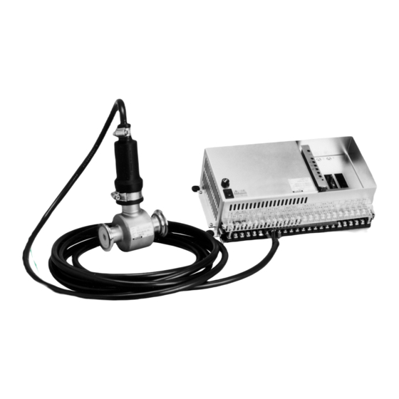
- Page 1 MagneW 3000 Electromagnetic Flowmeter Hyper-Fill Model: MGR13C (Converter) MGR11U (Detector) User’s Manual CM2-MGR100-2001 2nd edition...
- Page 2 In no event shall Azbil Corporation be liable to anyone for any indirect, special or consequential damages. This information and specifications in this document are subject to change without notice.
-
Page 3: Table Of Contents
Table of Contents 1: Overview..................1 2: Instrument installation ............2 2-1: Converter installation.................... 2 2-2: Detector Installation ....................3 2-3: Wiring ........................4 2-3-1: Converter wiring..........................4 2-3-2: Pulse output wiring ..........................6 2-3-3: Master-slave wiring..........................7 3: Configuration of the converter ..........8 3-1: Range........................ -
Page 5: 1: Overview
1 : Overview MagneW 3000 Hyper-Fill is developed for high speed batching and filling machine applications. Hyper-Fill is a magnetic flowmeter optimized for the sophisticated measurement demands found in filling applications. Model MGR13C/MGR11U - MagneW3000 Electromagnetic FLowmeter Hyper-Fill... -
Page 6: 2: Instrument Installation
Overview Azbil Corporation 2 : Instrument installation 2-1 : Converter installation (1) Mount the converter by four M4 screws. (M4 screws are not supplied with the converter.) (2) Rubber bush is attached to the bracket. Tighten the screws through the rubber bush and mount the converter. -
Page 7: Detector Installation
5 to 100% RH (2) The model MGR11U detector is designed using a standard one inch IDF clamp connection. We recommend to use the welding ferrule that Azbil Corporation supplies. For the accurate measurement, pipe inner diameter and ferrule inner diameter connected to the model MGR11U detector should be 15 mm ±0.2 mm. -
Page 8: Wiring
Overview Azbil Corporation Belt Water-proof cover Water-proof Water-proof Water-proof cover cover connector Flow direction arrow Belt Flow direction arrow Case Electrode Detector Figure 2 2-3 : Wiring 2-3-1 : Converter wiring Refer to the Table 1 and perform wiring. Turn off the power during wiring. - Page 9 Azbil Corporation Overview Table 1 Symbol Connect to Meaning H, N, E Connect to power supply. E for Power supply and earth earth ground. (85 to 264V AC) ground A1, B1, C1, Connect to the special cable model Flow rate signal...
-
Page 10: Pulse Output Wiring
Overview Azbil Corporation 2-3-2 : Pulse output wiring The pulse output is an open collector output. Pay attention to voltage and polarity when wiring. External power supply voltage 12 to 24V DC (30V max.) Output current 100 mA max. 5 μS typ. -
Page 11: Master-Slave Wiring
Azbil Corporation Overview 2-3-3 : Master-slave wiring If the Hyper-Fill flowmeter is installed more than five units, Hyper-Fill flowmeters consist of one master converter and slave converters. Number of units of the Number of unit of the Number of unit of the... -
Page 12: 3: Configuration Of The Converter
Overview Azbil Corporation 3 : Configuration of the converter Refer to the following configuration table printed to the main unit for the converter configuration. 400mL/s 100mL/s 200mL/s 800mL/s RANGE 800mL/s 0.1mL/P 400mL/s 0.05mL/P 0.1mL/P 30μs 200μs 200mL/s 0.05mL/P 0.1mL/P 100mL/s 0.05mL/P... -
Page 13: Pulse Width
Azbil Corporation Overview 3-3 : Pulse width 30 μS or 200 μS is selectable as a pulse width. Pulse width Tolerance 30 μs 30 μS ± 4 μs 200 μs 200 μS ± 22 μs Transient response of pulse output: 5 μs typ Pulse width of 200 μs is not applicable in case that pulse span frequency fs is 8000 Hz. -
Page 14: Master/Slave Configuration
Overview Azbil Corporation 3-5 : Master/slave configuration This function is used to minimize magnetic interference by detectors installed closely each other in the multiple head filling machine applications. A master converter sends synchronized signal for excitation to slave converters, thus avoiding output error due to magnetic interference. -
Page 15: 4: Operation
Azbil Corporation Overview 4 : Operation After configuration, follow below procedures before operation. 4-1 : Warm-up Turn ON the power. For accurate measurement, the electronics needs 30-minute warm-up time to stabilize. Once turn OFF the power and turn ON the power again, wait for 10-minute for electronics warm-up. -
Page 16: Span Adjustment
Overview Azbil Corporation Version 2 (PLS ZERO: button) (1) Fill the fluid inside of the flowtube and verify the fluid stops. (2) Zeroing the flowmeter. Push the button of the PLS ZERO for one second. Zero adjustment will be done automatically. If zero adjustment is done successfully, LED lights out for five seconds then light on. - Page 17 Note...
- Page 19 Document Number: CM2-MGR100-2001 Document Name: MagneW 3000 Electromagnetic Flowmeter Hyper-Fill Model: MGR13C / MGR11U User’s Manual Date: 1st edition: Mar. 2005 2nd edition: Aug. 2012 Issued/Edited by: Azbil Corporation...
Need help?
Do you have a question about the MagneW 3000 and is the answer not in the manual?
Questions and answers