Table of Contents
Advertisement
Quick Links
No. CP-SP-1454E
Flame Monitor
Model AUR355
User's Manual
Thank you for purchasing your Azbil
Corporation product.
This manual contains information for
ensuring the safe and correct use of the
product.
Those designing or maintaining
equipment that uses this product
should first read and understand
this manual. This manual contains
information not only for installation,
but also for maintenance,
troubleshooting, etc. Be sure to keep it
nearby for handy reference.
Advertisement
Table of Contents

Related Manuals for Azbil AUR355


Summary of Contents for Azbil AUR355
- Page 1 No. CP-SP-1454E Flame Monitor Model AUR355 User’s Manual Thank you for purchasing your Azbil Corporation product. This manual contains information for ensuring the safe and correct use of the product. Those designing or maintaining equipment that uses this product should first read and understand this manual.
- Page 2 Considerable effort has been made to ensure that this manual is complete and accurate, but if you should find an omission or error, please contact us. In no event is Azbil Corporation liable to anyone for any indirect, special, or consequential damages as a result of using this product.
- Page 3 Conventions Used in This Manual „ The safety precautions explained below aim to prevent injury to you and others, and to prevent property damage. Warnings are indicated when mishandling this product may WARNING result in death or serious injury. Cautions are indicated when mishandling this product may CAUTION result in minor injury or property damage only.
-
Page 4: Safety Precautions
Safety Precautions WARNING Before mounting, removing, or wiring, be sure to turn off the power to this device and all connected devices. Failure to do so may result in an electric shock. This device has functions that are extremely important for the safe operation of combustion equipment. - Page 5 CAUTION Installation, wiring, maintenance, inspection, and adjustment must be carried out by a professional with technical training in combustion equipment and combustion safety. Use this unit correctly within the range of the rated specifications stated in the user's manual. Not doing so may cause device failure or malfunction. Do not install this product in a place with any of the following characteristics.
- Page 6 CAUTION The pilot turn-down test should be carried out only by specialists who have knowledge and skills concerning combustion equipment and combustion safety. If the combustion equipment is restarted after a safety shutoff, do all of the inspection steps described in Chapter 5.
-
Page 7: The Role Of This Manual
The Role of This Manual There are four different manuals related to model AUR355. Read them as necessary for your specific requirements. If you do not have a manual you require, please contact us or one of our dealers. Flame Monitor Model AUR355 User’s Manual Document No. -
Page 8: Table Of Contents
Contents Conventions Used in This Manual Safety Precautions The Role of This Manual Chapter 1. Overview Handling Precautions „ Cautions for combustion equipment design „ Most important points for ensuring safety „ „ Precautions for system design „ Model No. „... - Page 9 Chapter 5. Trial Operation and Adjustment Preliminary inspection „ Inspection procedure „ Chapter 6. Maintenance and Inspection „ General maintenance and inspection „ Maintenance and inspection cycle „ Alarm codes and details „ What to do if E951 occurs „ Failure inspection flowchart Chapter 7.
-
Page 11: Overview
AUD300C advanced ultraviolet flame detector, the AUD500C explosion-proof advanced ultraviolet flame detector, or a flame rod. The AUR355 drives the shutter that is built into the AUD300C/500C to continuously check both its own flame detection circuit and the ultraviolet detector in order to provide flame detection for continuous burner operation. -
Page 12: Most Important Points For Ensuring Safety
Power (Reserved) (Reserved) Other Description model No. sensor sensitivity response voltage AUR355 − Flame rod UV flame detector Standard 4 s max. (nominal: 3 s) 2 s max. (nominal: 1.5 s) 100 V AC 200 V AC 220 V AC −... -
Page 13: Related Devices
DT : with tropicalization and inspection certificate YT : with traceability certificate and tropicalization Optional parts (sold separately) Model No. Name BC-R05A100 Dedicated sub-base (a requirement for the AUR355) 81447514-001 Connector for front wiring Weidmüller model number BL3.5/11F Compatible wire: 0.2–1.5 mm (28–14 AWG) -
Page 14: Installation And Wiring
Chapter 2. Installation and Wiring WARNING This device is equipped with functions that are extremely important for the safe operation of combustion equipment. Be sure to follow the instructions stated in this user’s manual. Before mounting, removing, or wiring, be sure to turn off the power to this device and all connected devices. -
Page 15: Installation Method
Use the contact reset input (terminal 24) for one AUR only. Do not use the terminal for contact reset input to other AUR355 devices. Do not share the output common (terminal 6) and the input common (terminals 19, 20) with other AUR355 devices. -
Page 16: Cautions Regarding Installation
Chapter 2. Installation and Wiring „ Cautions regarding installation • Leave space 50 mm above and below, 50 mm on the left and right, and 80 mm in the front as space for removal, wiring, and maintenance. Also, do not install this device close to electrical power devices or other sources of heat. -
Page 17: Mounting On A Din Rail
Chapter 2. Installation and Wiring „ Mounting on a DIN Rail (1) Pull down the sub-base’s DIN rail clamps. (2) Attach the sub-base to the DIN rail, making sure that the sub-base is not upside-down. (3) Push up the DIN rail clamps to fasten the sub-base to the DIN rail. Pull down Attach sub-base to DIN rail Push the DIN rail clamps... - Page 18 Chapter 2. Installation and Wiring CAUTION Turn the power off before mounting the device on the sub-base. Otherwise, device failure may result. „ Mounting the main unit on the sub-base (sold separately) and removing it Mounting (1) Align the indentation in the center of the top of the device with the projection on the sub-base.
-
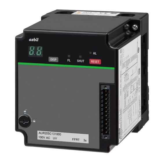
Page 19: Terminal Numbers, Front Panel Item Names
Chapter 2. Installation and Wiring „ Terminal numbers, front panel item names Front Sub-base (sold separately) Display RESET switch DISP switch Front connector Loader jack* DIN rail clamp Terminal block* Also used as a Smart Loader Package jack Firmly tighten the terminal screws with a torque of 0.5 N·m or less. „... - Page 20 Chapter 2. Installation and Wiring Front connector terminals Function Flame voltage output (+) FV− Flame voltage output (−) RS-485 (DA) RS-485 (DB) RS-485 (SG) − Not used − Not used − Not used − Not used − Not used − Not used LED indication Name...
- Page 21 Chapter 2. Installation and Wiring Connector for front wiring (model 81447514-001) terminal layout Mounting screw Wiring Screws for wiring Mounting screw Connector for front wiring (for right side wiring) (model 81447514-002) terminal layout Mounting screw Wiring Screws for wiring Mounting screw...
-
Page 22: (Terminals 1-24: Sub-Base; Terminals 25-35: Front Connector)
• After mounting the connector for front wiring, secure it in place with the mounting screw on the side of the connector. • Use the contact reset input (terminal 24) for one AUR only. Do not use the terminal for contact reset input to other AUR355 devices. - Page 23 • After mounting the connector for front wiring, secure it in place with the mounting screw on the side of the connector. • Use the contact reset input (terminal 24) for one AUR only. Do not use the terminal for contact reset input to other AUR355 devices.
-
Page 24: Connection With Model Aud300C/500C
Chapter 2. Installation and Wiring „ Connection with model AUD300C/500C Connect to the AUD300C or AUD500C as shown. AUD300C/500C This device 16 17 Blue White White Yellow Handling Precautions • AUD300C and 500C signal wires (blue and yellow) have polarity. Connect the blue wire to terminal 14 (F), and the yellow wire to terminal 15 (G). - Page 25 Chapter 2. Installation and Wiring Sample countermeasure for power surges caused by lightning When using a surge absorber as a countermeasure for power surges caused by lightning, connect it between terminal 3 and ground, as shown below. The mounting brackets of the surge absorber are electrically connected internally by crimping to the ground side of the absorber.
-
Page 26: Operating This Device
• Identifying information Item Notation Product number AUR355 _ _ _ _ _ _ _ Voltage AC _ _ _ V Timing Flame failure response time FFRT _ s 7-segment display lower-right LED dot If the dot at the bottom right of the 7-segment LED is blinking, initialize the settings. - Page 27 Chapter 3. Operating This Device z When an error occurs The 7-segment display alternately displays an alarm code and the code for the operating status where the fault stop occurred. Every time the DISP switch is pressed, the display changes between the flame voltage and alternate display of the alarm code and the operating status code when fault stop occurred.
- Page 28 Chapter 3. Operating This Device Event name Event No. Operation UV flame detector check Turns ON if the combustion time exceeds the value set for the UV flame detector (combustion time) (combustion time) checking time. Utilize this event for maintenance of the equipment, in order to know when to replace the flame detector, etc.
-
Page 29: Communication Setting Mode
Chapter 3. Operating This Device „ Communication setting mode (1) Press and hold the DISP switch for approximately 5 s or more during the stop status (when the start switch is OFF). The 7-segment display changes to C 1 and the system goes into communication setting mode. - Page 30 Chapter 3. Operating This Device 3. After making a selection, press the RESET switch. “H2” blinks, and when the blinking stops, configuration is complete. At this time, “H2” is displayed. • Communications format setting (H3) Use the DISP switch to select H3 on the 7-segment display. 1.
- Page 31 Chapter 3. Operating This Device Operation when the dot at the lower right of the 7-segment LED is blinking If the communication settings are not correctly configured during communication setup due to a power shutdown or other cause, this device stops abnormally due to communication settings error E971 and the 7-segment display alternately shows E9 and 7 1.
-
Page 32: How This Device Operates
Chapter 4. How This Device Operates CAUTION After turning on the power, allow sufficient time before checking the output of this device. This device does not start operation until about 8 seconds after power-on. After a fault stop is canceled, start input is not accepted for about 5 seconds. „... -
Page 33: Sequence Chart
Chapter 4. How This Device Operates „ Sequence chart The operation sequence of this device is shown below. Normal operation If the start input is turned ON when there is no flame signal, the device transitions to flame monitoring status (PF). If a flame signal is detected while the start input is ON, the two flame outputs (with and without start check) turn ON. - Page 34 Chapter 4. How This Device Operates Start ON Flame detection No ame detected Display 7-segment display Input Start input Flame signal Output Flame output (with start check) Flame output Flame relay N.C. output Operation Operation of this device SHUT 7-seg. Start input OFF All relays are OFF.
- Page 35 Chapter 4. How This Device Operates False flame If the start input turns ON while the flame signal is detected, the device transitions to false flame detection status (PE). The device shifts out of false flame detection status (PE) if the flame signal or the start input turns OFF. Flame detection Start ON No ame detected...
- Page 36 Chapter 4. How This Device Operates When shutter remains closed (AUR355C only) Regardless of whether the start input is ON or OFF, if the shutter is closed for 5 seconds or longer, the flame relay will turn OFF. While the shutter is closed, this device cannot detect the presence or absence of a flame (the period indicated by Start ON Flame detection...
-
Page 37: Instantaneous Power Outage / Voltage Drop During Operation
* Because the voltage to the fuel valve also drops, the fuel supply may decrease, causing flame failure. „ Playback monitor / flame logger The playback monitor and flame logger functions facilitate maintenance of equipment. For details, refer to Flame Monitor Model AUR355 User’s Manual for Communication Functions, No. CP-SP-1453E. -
Page 38: Chapter 5. Trial Operation And Adjustment
Chapter 5. Trial Operation and Adjustment WARNING The ignition time for the pilot and main burners should not exceed the time defined by the burner or device manufacturer. If it does, fuel will accumulate in the combustion chamber and form an explosive mixture, resulting in a very dangerous situation in which an explosion could occur. - Page 39 Chapter 5. Trial Operation and Adjustment Ignition spark response WARNING Make sure that the AUD flame detector does not detect ultraviolet rays from a source other than the burner. If the AUD detects other ultraviolet rays, it will continue to send flame detection signals even if the burner flame goes out.
- Page 40 Chapter 5. Trial Operation and Adjustment Handling Precautions • Ensure that the ultraviolet detector does not detect ultraviolet rays other than those from the burner flame. Sources of ultraviolet radiation (other than the burner flame) that can activate the AUD flame detector include the following. Examples: Ultraviolet ray sources 1371 °C or hotter red-hot furnace wall (within 50 cm...
- Page 41 The voltage can be checked on the 7-segment display or by connecting a flame meter to terminals 25 & 26 on the front connector. It is necessary to obtain a monitor/communication connector (81447514-001) to connect the FSP136A100 and the AUR355. Flame voltage display...
- Page 42 Pilot turn-down test WARNING For equipment that uses the AUR355 to detect both the pilot and the main burner flame, carry out the pilot turn-down test carefully. If the flame detector is set so that it detects a pilot flame that is too small to ignite the main burner, this device will not be able to detect a flame failure in the main burner.
- Page 43 Chapter 5. Trial Operation and Adjustment (6) Changing the gas pressure between minimum and maximum, repeat steps (1) to (5) to check if the main burner ignites without fail. Handling Precautions • If it is necessary to repeat this test, in order to prevent an explosion, stop all combustion equipment devices each time the test is finished, and completely discharge unburned gas or fuel that has accumulated in the chamber, ducts, and flues.
-
Page 44: Chapter 6. Maintenance And Inspection
Chapter 6. Maintenance and Inspection WARNING Before mounting, removing, or wiring, be sure to turn off the power to this device and all connected devices. Failure to do so may result in an electric shock. Do not touch terminal 14 (F) after turning the power off. An electric charge may remain on terminal 14 (F) and cause an electric shock. -
Page 45: Alarm Codes And Details
Chapter 6. Maintenance and Inspection „ Alarm codes and details If a fault stop occurs, the alarm code and the code for the operating status where the fault stop occurred are displayed alternately. Alarm Sub- Description Status Cancellation method code code Alarm at power-on When the cause of the fault stop cannot be identified... -
Page 46: What To Do If E951 Occurs
Chapter 6. Maintenance and Inspection Alarm Sub- Description Status Cancellation method code code Internal error Internal memory error in host communication setting Reset the error. (Communication setting) • In communication setting mode, the power The reset operation was turned off during configuration (when the initializes the 7-segment display was blinking), and data was not communication settings. -
Page 47: Failure Inspection Flowchart
• Check the view from the flame monitoring pipe for a light source causing false flame Did flame LED • Check flame voltage level turn OFF? • Check the AUR355 • Check the AUD300C/500C Did shutter LED (UV tube self-discharge, bent shutter blade, etc.) turn OFF? •... -
Page 48: Chapter 7. Specifications
Chapter 7. Specifications Item Description Application Gas- or oil-burning combustion equipment Compatible flame detector Model AUD300C/500C UV flame detector or flame rod Flame failure response time Model AUD300C/500C UV flame detector Flame rod 2 s max. or 4 s max. 4 s max. - Page 49 Chapter 7. Specifications Item Description General Protective IP40: if sideboards (81447515-001) are attached to the sub-base (model BC-R05) specifications structure IP10: (sub-base (model BC-R05) only) Overvoltage category Pollution degree Automatic action Type 2.A.V Software Class C Case color Black Case material Denatured PPE resin (UL 94-V0 PTI materials group IIIa) General Structure...
-
Page 50: X84; Dimensions
Chapter 7. Specifications „ Dimensions Main unit Unit:mm Sub-base (sold separately) Main unit mounting screw Sub-base (sold separately) Connector for front wiring Main unit mounting screw DIN rail clamp Model No. of connector for front wiring 81447514-001 10.6 81447514-002 14.6... - Page 51 Chapter 7. Specifications Sub-base model BC-R05A100 (sold separately) Unit:mm Knockout hole Knockout hole M3.5 (terminal screw) φ12 φ12 Knockout hole Knockout hole Sub-base Sub-base mounting hole mounting hole 62.5 DIN rail clamp Sideboard model 81447515-001 (sold separately) 30.7 Sub-base φ19 Sub-base knockout hole Sideboard...
- Page 53 Revision History (CP-SP-1454E) Date Edn. (New) Page No. Description June 2021...
- Page 54 Warranty period and warranty scope 1.1 Warranty period Azbil Corporation’s products shall be warranted for one (1) year from the date of your purchase of the said products or the delivery of the said products to a place designated by you.
- Page 55 Although acceleration of the above situation varies depending on the conditions or environment of use of the products, you are required not to use any Azbil Corporation’s products for a period exceeding ten (10) years unless otherwise stated in specifications or instruction manuals.
- Page 56 Specifications are subject to change without notice. (11) 1-12-2 Kawana, Fujisawa Kanagawa 251-8522 Japan URL: https://www.azbil.com 1st edition: Jun. 2021 (S)
Need help?
Do you have a question about the AUR355 and is the answer not in the manual?
Questions and answers