Table of Contents
Advertisement
Quick Links
(Not for use in Japan)
No. CP-SP-1471E
Sapphire Capacitance
Diaphragm Gauge
Model V8
User's Manual
for EtherCAT
Communication Functions
Thank you for purchasing your Azbil
Corporation product.
This manual contains information for
ensuring the safe and correct use of
the product.
Those designing or maintaining
equipment that uses this product
should first read and understand
this manual. This manual contains
information not only for installation,
but also for maintenance,
troubleshooting, etc. Be sure to keep it
nearby for handy reference.
Advertisement
Table of Contents

Subscribe to Our Youtube Channel
Related Manuals for Azbil V8


Summary of Contents for Azbil V8
- Page 1 Sapphire Capacitance Diaphragm Gauge Model V8 User’s Manual for EtherCAT Communication Functions Thank you for purchasing your Azbil Corporation product. This manual contains information for ensuring the safe and correct use of the product. Those designing or maintaining equipment that uses this product should first read and understand this manual.
- Page 2 Considerable effort has been made to ensure that this manual is complete and accurate, but if you should find an omission or error, please contact us. In no event is Azbil Corporation liable to anyone for any indirect, special, or consequential damages as a result of using this product.
- Page 3 Conventions Used in This Manual „ The safety precautions explained below aim to prevent injury to you and others, and to prevent property damage. Warnings are indicated when mishandling this product may WARNING result in death or serious injury. Cautions are indicated when mishandling this product may CAUTION result in minor injury or property damage only.
-
Page 4: The Role Of This Manual
The Role of This Manual There are four different manuals related to model V8. Read them as necessary for your specific requirements. If you do not have a manual you require, please contact us or one of our dealers. Sapphire Capacitance Diaphragm Gauge Model V8 User’s Manual for EtherCAT Communication Functions Document No. -
Page 5: Ethercat Communication
EtherCAT Communication EtherCat is an Ethernet-based real-time fieldbus system proposed and developed by Beckhoff Automation GmbH, ® Germany. Since it is based on the Ethernet protocol, general-purpose Ethernet cables can be used when setting up a network. -
Page 6: Table Of Contents
Contents Conventions Used in This Manual The Role of This Manual EtherCAT Communication Chapter 1. Overview The EtherCAT interface „ Definition of terms „ Appearance „ „ Connector pin assignment „ Cable and connection method „ LED indicator and switches „... - Page 7 Appendix App.-1 Reference materials App.-1 „ EtherCAT terms App.-2 „...
-
Page 9: Overview
Chapter 1. Overview „ The EtherCAT interface Item Description Notes Communication A special protocol for EtherCAT – protocol – Communication IEC 61158-2 (Ed. 4.0) standards IEC 61158-3/4/5/6-12 (Ed 1.0) – Data rate 100 Mbps Device identification Explicit Device Identification is supported. Rotary switches for ID selector method –... -
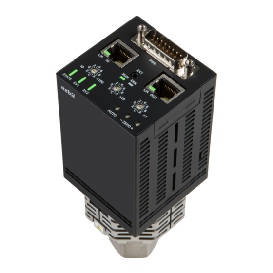
Page 10: Appearance
Chapter 1. Overview „ Appearance Separated model Integrated model Label Description EtherCAT IN connector EtherCAT OUT connector ID × 100 Rotary switches for ID selector ×100 (hex.) ×10 Rotary switch for ID selector ×10 (hex.) ×1 Rotary switch for ID selector ×1 (hex.) Link Activity EtherCAT IN Link Activity EtherCAT OUT EtherCAT status LED... -
Page 11: Connector Pin Assignment
Chapter 1. Overview „ Connector pin assignment The network ports of this device are used as follows. Pin No. Signal Description TX + Transmitted data (+) TX − Transmitted data (−) RX + Received data (+) – 75 Ω terminating resistor connection –... -
Page 12: Led Indicator And Switches
Safe-operational status (SAFEOP) Communication of cyclic data is in progress. The input data (TxPDO) is valid, but the output data (RxPDO) is not output. Note: Data sent from the master (RxPDO) will not be saved on the V8. Flickering BOOT (Bootstrap status) An EtherCAT error has not occurred or the device is not turned on. - Page 13 Chapter 1. Overview Rotary switches for ID selector To specify an EtherCAT device ID, use the three rotary switches with hexadecimal symbols (0–F). The specified value is used as an Explicit Device Identification, as defined in the EtherCAT specifications. The switches with ×100, ×10, and ×10 labels correspond to the 3rd, 2nd, and 1st digit of a hexadecimal number respectively.
-
Page 14: Pressure Value
Chapter 1. Overview „ Pressure value The pressure (“Value”) is calculated with the following formula, using the pre- compensation pressure: Pressure = GCS × (pre-compensation pressure + AZO) + OCS The values of GCS, AZO, and OCS are determined by the following objects. Term Name Index... - Page 15 Chapter 1. Overview The functions available for each trip point are indicated in the table below. TPn means the number n trip point (n= 1, 2, 3, or 4). ✓: supported – : not supported Name TP1/TP2 TP3/TP4 ✓ High Trip Enable ...
-
Page 16: Event Output
Chapter 1. Overview „ Event output This device has four (PhotoMOS) event output ports. The following functions can be assigned to an event. The polarity of the output can be changed. Name Abbrev. Function selection • Event 1 Outputs trip point (TP1) •... - Page 17 Chapter 1. Overview Warm-up status output Warm-up completion status is output. The definition differs depending on the model. Product Warm-up status output Model without self-heating Model with self-heating function function Warm-up is not completed.* Always ON Warm-up is completed.* * Warm-up is complete when the following condition is met: •...
-
Page 18: Pdo Mapping
Chapter 1. Overview „ PDO mapping The default TxPDO mapping is as follows. PDO Index PDO Entry PDO Entry Data type Name SubIndex Index Subindex 0x1A00 0x01 6001 0x01 BOOL Reading Valid* 0x02 6001 0x02 BOOL Overrange Exceeded 0x03 6001 0x03 BOOL Underrange Exceeded... -
Page 19: Object Dictionary
Chapter 2. Object Dictionary The general structure of the CoE object dictionary is as follows (all the index numbers in the following tables are in hexadecimal notation). Index Object dictionary areas 1000–1FFF Communication profile area 2000–5FFF Manufacturer-specific profile area 6000–6FFF Input area 7000–7FFF Output area... - Page 20 Chapter 2. Object Dictionary • The value of an object with Access = RW and nv (nonvolatile) attributes can be stored in nonvolatile memory (NVRAM). To do so, execute the Store Parameters Command (0xFBF2). Note that, if the power is turned off or the setting is reset without saving the value to NVRAM, a change in the value will be invalid (the setting will revert to the previously stored value).
-
Page 21: Communication Profile Objects (0X1000-0X1Fff)
Data type Access Value Name 1000 UDINT 0x138b Device Type 1001 USINT 0x00 Error register* 1008 V_STRING “V8” Manufacturer Device name 1009 V_STRING E.g., “1.1.1.1” Manufacturer Hardware Version 100A V_STRING E.g., “1.2.51” Manufacturer Software Version 100B V_STRING “0.0.00” Manufacturer Bootloader Version... - Page 22 Chapter 2. Object Dictionary Index Object Code/SI Data type Access Value Name 1C00 ARRAY Sync Manager Type 0x01 USINT 0x01 MailBox write 0x02 USINT 0x02 MailBox read 0x03 USINT 0x03 Process output data 0x04 USINT 0x04 Process input data 1C12 ARRAY Sync Manager 2 Assignment (max.
-
Page 23: Sync Manager Parameter (0X1C32, 0X1C33)
Chapter 2. Object Dictionary „ Sync Manager Parameter (0x1C32, 0x1C33) Sync Manager Parameter Values (0x1C32, 0x1C33) Name Access Value Note Synchronization Type 0x0000 or 0x0001 FreeRun, SM synchronous Cycle Time* Local cycle time of application controller Synchronization Types Supported 0x4003 FreeRun, SM synchronous Minimum Cycle Time 0x41eb0... - Page 24 *1. Abbreviations; rx: RxPDO mappable object, tx: TxPDO mappable object, nv: nonvolatile data User's Manual for Smart Loader Package Model SLP-V8 for Sapphire Capacitance Diaphragm Gauge Model V8, CP-SP-1472E. *3. A warning will be issued if an invalid parameter value was specified.
- Page 25 10 V is output by forced 0–10 V output can be written.* *1. Unit of pressure set in Data Units (0xF840.0x01). User's Manual for Smart Loader Package Model SLP-V8 for Sapphire Capacitance Diaphragm Gauge Model V8, CP-SP-1472E (for detailed operation).
- Page 26 Chapter 2. Object Dictionary Relay 3 Configuration (0x4001) Name Unit Description Setting range Default 0x01 Output mode – Enables or disables the Bit 0: Polarity Bit 0: 0 (positive) High/Low Trip Point Limit (0: positive, 1: negative) Bit 1: 0 (disabled) judgment.
- Page 27 Chapter 2. Object Dictionary Relay 4 Configuration (0x4002) Name Unit Description Setting range Default 0x01 Output mode – Enables or disables the Bit 0: Polarity Bit 0: 0 (positive) High/Low Trip Point Limit (0: positive, 1: negative) Bit 1: 0 (disabled) judgment.
- Page 28 *2. The value set in 0x5001.0x09 is valid as the self-heating temperature setting. User's Manual for Smart Loader Package Model SLP-V8 for Sapphire Capacitance Diaphragm Gauge Model V8, CP-SP-1472E. *4. The selectable DI function and the default setting differ depending on the model number. For details on the DI function...
-
Page 29: Input Area (0X6000-0X6Fff)
Chapter 2. Object Dictionary „ Input Area (0x6000–0x6FFF) Index Object Code/SI Data type Access rx/tx, nv Name 6000 RECORD Input Common 0x0D BOOL New message in the diagnosis history 0x0E BOOL TxPDO state (0: invalid, 1: valid) 0x0F BIT2 Input cycle counter 0x11 REAL Sensor value... -
Page 30: Output Area (0X7000-0X7Fff)
Chapter 2. Object Dictionary „ Output Area (0x7000–0x7FFF) Index Object Code/SI Data type Access rx/tx, nv Name 7000 RECORD Output Common 0x0F BIT2 Output cycle counter „ Configuration Area (0x8000–0x8FFF) Index Object Code/SI Data type Access rx/tx, nv Name 8001 RECORD Configuration Capacitance Diaphragm 0x11... - Page 31 Chapter 2. Object Dictionary Configuration Capacitance Diaphragm (0x8001) Name Unit Description Setting range Default 0x11 Sensor Temperature °C Specify the self-heating Select* temperature setting. 0x12 OCS: Offset The offset for the pressure −20 to +20 % FS of the 0 % FS of the pressure Customer Specific* reading can be changed.
- Page 32 Chapter 2. Object Dictionary Configuration Trip Point 2 (0x800F) Name Unit Description Setting range Default 0x01 High Trip Enable – Enables or disables the High False: disabled False: disabled Trip Point Limit judgment. True: enabled 0x02 Low Trip Enable – Enables or disables the Low False: disabled True: enabled...
-
Page 33: Information Area (0X9000-0X9Fff)
Chapter 2. Object Dictionary „ Information Area (0x9000–0x9FFF) Index Object Code/SI Data type Access rx/tx, nv Name 9000 RECORD Information Common 0x01 REAL Accumulated zero offset 0x02 REAL Highest Informational Measurement Value 0x03 REAL Highest Precision Measurement Value 0x04 REAL Lowest Precision Measurement Value 0x05 REAL... -
Page 34: Device Area (0Xf000-0Xfaff)
Chapter 2. Object Dictionary „ Device Area (0xF000–0xFAFF) Index Object Code/SI Data type Access Value Name F000 RECORD Semiconductor device profile 0x01 UINT 0x10 Index distance 0x02 UINT Maximum number of modules F010 ARRAY Module profile list 0x01 UDINT 0x0820 SubIndex 001 Index Object Code/SI Data type... - Page 35 Chapter 2. Object Dictionary Active Exception Status (0xF380.0x01) Description Value Bits 4–7 Reserved Bit 3 Manufacturer error Bit 3 = F384.0x01 & F3A4.0x01 Bit 2 Device error Bit 2 = F383.0x01 & F3A3.0x01 || F387.0x01 & F3A7.0x01 Bit 1 Manufacturer warning Bit 1 = F382.
- Page 36 Chapter 2. Object Dictionary Active Global Device Warning/Error (0xF385.0x01, 0xF387.0x01) V8 code ETG.5003.2080 definition Warnings (0xF385) Errors (0xF387) Bits 16–31 Reserved – – Bit 15 Reserved – – Bit 14 Reset exception – Bit 13 Notify vendor – – Bit 12 Scheduled maintenance due –...
- Page 37 Chapter 2. Object Dictionary Active Device Error (0xF383.0x01) ETG.5003.2080 definition V8 code Bit 31 Configuration exception Bits 3–30 Reserved – Bit 2 Electronics over-temperature Bit 1 Electronics failure Bit 0 Diaphragm failure 2-19...
-
Page 38: Manufacturer Error/Warning (0Xf384.0X01, 0Xf382.0X01)
Chapter 2. Object Dictionary „ Manufacturer Error/Warning (0xF384.0x01, 0xF382.0x01) V8 code ETG.5003.2080 definition 0xF384.0x01 0xF382.0x01 Bit 31 CPU exception error – Bit 30 Run-time error – Bit 29 Initializing error – Bit 28 Program ROM – Bit 27 Parameter NVRAM –... - Page 39 Chapter 2. Object Dictionary CDP Device Specific Inputs Index Object Code/SI Data type Access rx/tx, nv Name F641 RECORD Trip Point Output All 0x01 UDINT Trip Point Output All Instance* F6F0 ARRAY Input Latch Local Timestamp 0x01 UDINT SubIndex 001 F6F2 ARRAY Input Latch ESC Timestamp (64 bits)
- Page 40 SubIndex 001 F9F6 UDINT – – Time since power-on F9F7 UDINT – – Total time powered F9F8 UDINT – Firmware update functional generation number* *1. Azbil Corporation *2. Firmware update is supported, but it is not a public function. 2-22...
-
Page 41: Device Command (0Xfb00-0Xfbff)
Chapter 2. Object Dictionary „ Device Command (0xFB00–0xFBFF) Index Object Code/SI Data type Access tx/rx, nv Name FB40 RECORD Zero Adjust Command 0x01 ARRAY [0–5] OF BYTE – Command* 0x02 USINT – Status 0x03 ARRAY [0–2] OF BYTE – Response FBF0 RECORD Device Reset Command... - Page 42 Chapter 2. Object Dictionary Index Object Code/SI Data type Access tx/rx, nv Name FBF3 RECORD Calculate Checksum Command 0x01 ARRAY [0–3] OF BYTE – Command Read: byte [0]: 0x81 Write: byte [0]: 0x01 Byte [1–3]: Shall be zero Write bit 0: Use default checksum algorithm of the slave.
-
Page 43: Zero Point Adjustment Process
Chapter 2. Object Dictionary The following response will be returned. Value of Description SI=3 (response) Description SI=2 No errors, no reply available 254 (= no previous Zero Adjust After power-on, an attempt to read was command issued) made, but there was no previous Zero Adjust command.* No errors, reply available 0 (= command resp. -
Page 44: Zero Adjust Command Operation
Chapter 2. Object Dictionary „ Zero Adjust command operation When the EtherCAT Zero Adjust command (FB40) is issued with the setting “0” (zero adjustment without specified offset), the AZO value is rewritten so that pre- compensation pressure + AZO = zero, regardless of the OCS value. When the setting is “1”... -
Page 45: Diagnosis History
DiagCode Diagnosis code to identify the diagnosis message Bits 0–15 = 0x0000-0xDFFF Not used Bits 0–15 = 0xE000-0xE7FF Azbil-specific code (see the following section) Bits 0–15 = 0xE802 Module related messages (incl. module number assignment) Bits 16–23: Module No, 1 = 1'st module Bits 24–31: 0x00... - Page 46 Chapter 2. Object Dictionary Azbil-specific diagnosis code Value Exception Note 0x0000e000 Auto zero adjustment – 0x0000e802 User parameter – 0x0002e000 FRAM access error – 0x0003e000 FLASH write times over – 0x0004e000 Pressure range over – 0x0005e000 Aux. pressure range over –...
-
Page 47: Other
Chapter 2. Object Dictionary „ Other Complete Access Writing by SDO Complete Access is not supported for the objects below. If attempted, an Unsupported Access error will be returned. Index Description 4000 Analog Output Configuration 4001 Event 3 Configuration 4002 Event 4 Configuration 4003 Misc. -
Page 49: Exception Status
Chapter 3. Exception Status There are three types of exception status: error, alarm, and warning. Exception category Description Error There may be a problem with the product. It may be necessary to replace the device. Alarm The operating conditions exceeded the specifications, possibly affecting device performance. -
Page 50: Alarm
Chapter 3. Exception Status „ Alarm Details on alarms are given below. Code Item Conditions for detection Notes User parameter User parameter setting error Invalid values were set for user parameters (e.g., invalid EV3/EV4 value) (e.g., invalid EV3/EV4 value) This alarm is usually caused by a problem during use of the Smart Loader Package. - Page 51 Chapter 3. Exception Status Code Item Conditions for detection Notes Pressure The pressure is outside the accuracy- 0–100 % FS of the pressure range guaranteed range. Note that this warning will not be issued immediately if the pressure exceeds the accuracy-guaranteed range during power-on.
-
Page 52: Info
Chapter 3. Exception Status „ Info Code Item Conditions for detection Notes Mode time-out Automatic zero point adjustment Time-out that occurs during internal (Fixed at 3 minutes) time-out, etc. processing Ex.: Parameters must be locked by the loader when accessed, and timeout will occur if they are locked for longer than a certain period of time. -
Page 53: Esi File
Chapter 4. ESI File The ESI file for the V8 can be downloaded from the website indicated below (search for V8, “Download product documents, ” and “EtherCAT ESI file”). Compo Club URL: https://www.compoclub.com/ EtherCAT ESI file: V8-ESI-rev0x07.xml... -
Page 55: Troubleshooting
Chapter 5. Troubleshooting „ Judgment based on the EtherCAT ERROR LED lighting The type of error in this device can be known from the status of the EtherCAT ERROR LED. If the problem persists even after taking the following countermeasures, replace this device. - Page 57 Appendix „ Reference materials Document Description Version ETG.1000.2 Physical Layer Service Definition and Protocol Specification – ETG.1000.3 Data Link Layer Service Definition – ETG.1000.4 Data Link Layer Protocol Definition – Application Layer Service Definition ETG.1000.5 – ETG.1000.6 Application Link Layer Protocol Definition –...
- Page 58 Appendix „ EtherCAT terms Term Expanded Term Description EtherCAT Slave Information Slave device information Slave Information Interface Slave device basic information Process Data Objects Cyclic data TxPDO Transmit PDO Cyclic data that a master device reads out from a slave device RxPDO Receive PDO...
- Page 59 Revision History of CP-SP-1471E Date Rev. (New) Page No. Description Dec. 2022...
- Page 62 Warranty period and warranty scope 1.1 Warranty period Azbil Corporation’s products shall be warranted for one (1) year from the date of your purchase of the said products or the delivery of the said products to a place designated by you.
- Page 63 Although acceleration of the above situation varies depending on the conditions or environment of use of the products, you are required not to use any Azbil Corporation’s products for a period exceeding ten (10) years unless otherwise stated in specifications or instruction manuals.
- Page 64 Specifications are subject to change without notice. (11) 1-12-2 Kawana, Fujisawa Kanagawa 251-8522 Japan URL: https://www.azbil.com 1st edition: Dec. 2022 (S)
Need help?
Do you have a question about the V8 and is the answer not in the manual?
Questions and answers