Table of Contents
Advertisement
Quick Links
No. CP-SP-1190E
TM
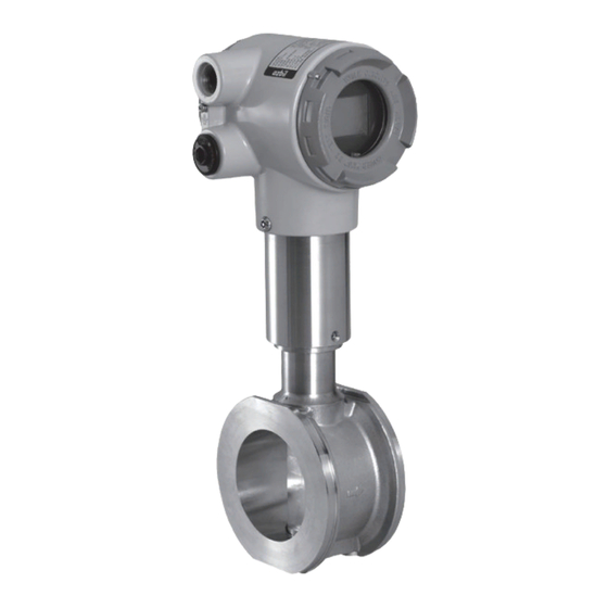
MVF050/080/100/150
Micro Flow
Vortex Gas Flowmeter
User's Manual
Thank you for purchasing an Azbil
Corporation product.
This manual contains information for
ensuring the correct use of this prod-
uct. It also provides necessary informa-
tion for installation, maintenance, and
troubleshooting.
This manual should be read by those who
design and maintain equipment that uses
this product. Be sure to keep this manual
nearby for handy reference.
Advertisement
Table of Contents

Subscribe to Our Youtube Channel
Related Manuals for Azbil MVF Series


Summary of Contents for Azbil MVF Series
- Page 1 No. CP-SP-1190E MVF050/080/100/150 Micro Flow Vortex Gas Flowmeter User’s Manual Thank you for purchasing an Azbil Corporation product. This manual contains information for ensuring the correct use of this prod- uct. It also provides necessary informa- tion for installation, maintenance, and troubleshooting.
- Page 2 If you should find an error or omission, please contact the azbil Group. In no event is Azbil Corporation liable to anyone for any indirect, special or consequential damages as a result of using this product. © 2005-2013 Azbil Corporation All Rights Reserved.
- Page 3 Conventions Used in This Manual ■ The safety precautions explained in the following section aim to prevent injury to the operator and others, and to prevent property damage. WARNING Warnings are indicated when mishandling this product might result in death or serious injury. CAUTION Cautions are indicated when mishandling this product might result in minor injury to the user, or physical damage to the product.
- Page 4 Safety Precautions WARNING If this device is used with flammable gases such as natural gas, propane or butane, mount it on the upstream side of the safety shutoff valve. When air gets in the pipe and an explosive mixture is produced, and if a sensor should make a spark due to lightning or other reasons, the mixture may explode inside the pipe.
- Page 5 The Role of This Manual A total of 2 different manuals are available for the MVF Series. Read them as necessary for your specific require- ments. If a manual you require is not available, contact the azbil Group or its dealer.
- Page 6 Organization of the Manual This manual is organized as follows. Chapter 1. INTRODUCTION This chapter describes features on this device. Chapter 2. NAMES AND FUNCTIONS OF PARTS This chapter describes the NAMES AND FUNCTIONS OF PARTS on this device. Chapter 3. INSTALLATION, MOUNTING, WIRING This chapter describes installation, mounting and wiring on this device.
-
Page 7: Table Of Contents
Contents Conventions Used in This Manual Safety Precautions The Role of This Manual Organization of the Manual Chapter 1. INTRODUCTION ■ ■ Introduction . . . . . . . . . . . . . . . . . . . . . . . . . . . . . . . . . . . . . . . . . . . . . . . . . . . . . . . . . . . . . . . . . . . . . . . . . . . . . . . . . . . . . . ■... -
Page 9: Chapter 1. Introduction
Chapter 1. INTRODUCTION ■ Introduction The MVF Series Micro Flow Vortex Gas Flowmeter (hereafter called the MVF) is a thermal vortex gas flowmeter featuring a wide measurement range. It uses the Azbil Corporation-designed Micro Flow sensor (or “µF sensor”) as a vortex generator. -
Page 10: Model Selection Table
Chapter 1. INTRODUCTION ■ Model selection table The following shows the model Nos. for this flowmeter: ● SUS304 Basic Flow and Option Pipe Model Connection Commu- model Material Output Power mounting Appended Descripton size type method type nication direction Micro Flow Vortex Flowmeter Pipe size 50A (2B) Pipe size 80A (3B) Pipe size 100A (4B) - Page 11 Chapter 1. INTRODUCTION ● SCS13A Basic Flow and Option Pipe Model Connection Commu- model Material Output Power mounting Appended Descripton size type method type nication direction Micro Flow Vortex Flowmeter Pipe size 50A (2B) Pipe size 80A (3B) Pipe size 100A (4B) Pipe size 150A (6B) With temperature and pressure compensation, standard operating pressure range 0–1.0 MPa...
-
Page 12: Chapter 2. Names And Functions Of Parts
Chapter 2. NAMES AND FUNCTIONS OF PARTS ■ Body Converter Label Terminal housing cover Wiring port Display Terminal block Gauge pressure sensor A-A cross-section of ow passage Flow direction F sensor F sensor Pipe connector (wafer) Vortex generator Display Used for the display of instantaneous flow rate, integrated flow rate, and alarm status and error of this device. -
Page 13: Display
Chapter 2. NAMES AND FUNCTIONS OF PARTS ■ Display CAUTION Before pressing the reset switch, touch a metal surface such as the housing of the device to dis- charge static electricity. Reset switch OVER setting m/min 7-segment display upper kg/h 7-segment display lower ¥... -
Page 14: Chapter 3. Installation, Mounting, Wiring
Chapter 3. INSTALLATION, MOUNTING, WIRING WARNING If this device is used with flammable gases such as natural gas, propane or butane, mount it on the upstream side of the safety shutoff valve. When air gets in the pipe and an explosive mixture is produced, and if a sensor should make a spark due to lightning or other reasons, the mixture may explode inside the pipe. -
Page 15: Installation
Chapter 3. INSTALLATION, MOUNTING, WIRING ■ Installation Avoid mounting this device in the following locations: • Locations whose ambient temperature falls below −15˚C and rises above +60˚C • Locations whose ambient humidity exceeds 90 %RH • Locations subject to sudden changes in temperature and condensation • Locations be filled with corrosive gases and flammable gases • Locations where there are lots of conductive substances (e.g. - Page 16 Chapter 3. INSTALLATION, MOUNTING, WIRING • Provide a straight pipe section in upstream side and downstream side of the in- stallation location. Use Sch 20 pipe for 50A, and Sch 40 pipe for 80A/100A/150A. D indicates the connecting port size. Secure the length of more than 5D for the downstream pipe section.
- Page 17 As shown in the above figure, provide the devices eliminating the foreign matters such as oil, water and iron powder, and install a receiver tank as the measures against pulsating flow ; at the upstream of MVF series. • Take effective countermeasures in case of installation near a pump or roots blower.
-
Page 18: Piping Work
Chapter 3. INSTALLATION, MOUNTING, WIRING ■ Piping work WARNING The mass of this device is 7 to 23 kg according to the model number. Ensure to take complete precautions and care while handling for transportation or installation. For safe handling, two or more persons are required while handling this device. Accidental dropping of the device on the foot might cause injury. - Page 19 Chapter 3. INSTALLATION, MOUNTING, WIRING ● Flange shape Use a flange which can secure a large contacting area with a gasket. Good example Bad example Flange gasket (As the contacting Welded Welded area with a gasket is portion portion small, there is a fear of leakage.) Pipe ●...
-
Page 20: Wiring
Chapter 3. INSTALLATION, MOUNTING, WIRING ■ Wiring CAUTION When connecting the load to the output terminals, do not exceed the rated value shown in the specifications. Doing to do so might cause the damage of this device. Before wiring, be sure to turn the power OFF. Before supplying power, be sure to check that there is no wiring error. - Page 21 Chapter 3. INSTALLATION, MOUNTING, WIRING (3) Remove the terminal cover. (4) Put the packing on the supplied waterproof gland. (5) Pass the cable through the waterproof gland, and mount the waterproof gland in the wiring port. Handling precautions • Never remove the packing from the waterproof gland. • Use a cable that is 6 to 12 mm in diameter.
- Page 22 Chapter 3. INSTALLATION, MOUNTING, WIRING (3) When leading out the wiring from two ports, remove the plug also. (4) Remove the terminal cover. (5) Connect an electrical wiring conduit. (6) Pass the wiring through the electrical wiring conduit and then connect the wiring to the terminal block.
- Page 23 Chapter 3. INSTALLATION, MOUNTING, WIRING ● Terminal layout Wiring label Terminal No. Signal name Description RS-485 communication DA RS-485 communication DB Unused Do not use Unused Do not use Pulse output (NPN open collector) Common RS-485 communication common +24V 24 V power Common 4 to 20 mA output Ground terminal...
-
Page 24: Chapter 4. Troubleshooting
Make sure that the correct power voltage being applied and the polarity are correct. Make sure that the electric wires are connected. ■ Error message (faulty operation) When an error message is displayed, contact the azbil Group. Repair at Azbil Corporation is required. Error... -
Page 25: Alarm Display
Chapter 4. TROUBLESHOOTING ■ Alarm display If conditions exceed the device's specified range, an alarm message and the instan- taneous flowrate are displayed alternately. In order to use this device within an al- lowable range, change the conditions of the fluid. Alarm Cause display... -
Page 26: Chapter 5. Specifications
Output intervals of less than 1s: duty ratio 50 % Communication function 1 RS-485 interface, Transmission line: 3-wire system Communication distance: 300 m max. Compatible with Azbil Corporation's products (CMC15G, etc.) Transmission speed: 2400, 4800, 9600, 19200 bps Integrated value, instantaneous, value/warning, and settings can be recorded. -
Page 27: Specifying Accuracy
Chapter 5. SPECIFICATIONS Item Specifications MVF050 MVF080 MVF100 MVF150 Wiring port Connection port: 2 locations, Connection standard: G1/2 female thread Accessories: 2 water-proof glands attached Sealing IP67 (JIS C 0920 and IEC 529 Water-proof and dust-proof structure on the assumption of outdoor installation) Applicable standard EN61326-2-3: 2006, EN61326-1: 2006... - Page 28 Chapter 5. SPECIFICATIONS We will calculate the following items: 1. Minimum measurable flow rate 2. Maximum measurable flow rate 3. Accuracy after temperature and pressure correction (examples: for 100 and 150 m /h (normal)) 1. Minimum measurable flow rate (volumetric flow rate (m /h) and mass flow rate (m /h (normal)) First, the minimum measurable velocity is determined as the larger of 0.3 m/s or...
- Page 29 Chapter 5. SPECIFICATIONS 3. Accuracy after temperature and pressure correction As an example, we will calculate the accuracy after temperature and pressure cor- rection at 100 m /h and 150 m /h (normal), using the following formula: Accuracy after volumetric flow temperature pressure (%RD) = ( (%RD)
- Page 30 Chapter 5. SPECIFICATIONS At 100 m /h (normal), the accuracy is 4.6 % RD. The calculation for the flow rate of 150 m /h (normal) is performed similarly. Re = 49517 (velocity = 1.2 m/s). Since the Reynolds number is more than 35000, the volumetric flow rate accuracy is ±2 % RD.
-
Page 31: Tables For Specifying Volumetric Flow Rate Accuracy (In Air)
Chapter 5. SPECIFICATIONS ■ Tables for specifying volumetric flow rate accuracy (in air) Flow rate unit of measurement: m /h (normal) Accuracy is measured at a fluid temperature of 23 °C. Accuracy differs according to operating pressure and flow rate ranges. ●... -
Page 32: Tables For Accuracy After Temperature And Pressure Correction (In Air)
Chapter 5. SPECIFICATIONS ■ Tables for accuracy after temperature and pressure correction (in air) Flow rate unit of measurement: m /h (normal) Accuracy is measured at a fluid temperature of 23 °C. Accuracy differs according to operating pressure and flow rate ranges. (1) Operating pressure range 0-0.1 MPa: MVF_ _ _1 ●... - Page 33 Chapter 5. SPECIFICATIONS (2) Operating pressure range 0-0.3 MPa: MVF_ _ _3 ● MVF0503 ● MVF0803 Minimum Minimum Operating Operating measurable measurable pressure Accuracy pressure Accuracy flow rate flow rate (MPa) (MPa) Q min Q min ±Q min ±5.4 %RD ±4.1 %RD ±Q min ±5.4 %RD ±4.1 %RD...
- Page 34 Chapter 5. SPECIFICATIONS (3) Operating pressure range 0-1.0 MPa: MVF_ _ _0 ● MVF0500 ● MVF0800 Minimum Minimum Operating Operating measurable measurable pressure Accuracy pressure Accuracy flow rate flow rate (MPa) (MPa) Q min Q min ±Q min ±5.1 %RD ±3.8 %RD ±Q min ±5.1 %RD ±3.8 %RD...
-
Page 35: Pressure Loss
Chapter 5. SPECIFICATIONS ■ Pressure loss MVF050 (Pipe size 50A) MVF080 (Pipe size 80A) MVF100 (Pipe size 100A) MVF150 (Pipe size 150A) ● Primary pressure 0.01 MPa ● Primary pressure 0.3 MPa 800 1000 1200 1400 1600 1800 2000 1000 2000 3000 4000 5000 6000... -
Page 36: External Dimensions
Chapter 5. SPECIFICATIONS ■ External dimensions ● MVF050_S (Pipe size 50A) Unit : mm Φ59 52.5 ● MVF080_S (Pipe size 80A) Φ59... - Page 37 Chapter 5. SPECIFICATIONS ● MVF050_C (Pipe size 50A) Φ59 52.5 ● MVF080_C (Pipe size 80A) Φ59...
- Page 38 Chapter 5. SPECIFICATIONS ● MVF100_S (Pipe size 100A) Φ59 96.8 ● MVF150_S (Pipe size 150A) Φ59 Eyebolt...
- Page 39 Chapter 5. SPECIFICATIONS ● MVF100_C (Pipe size 100A) Φ59 96.8 ● MVF150_C (Pipe size 150A) Φ59 Eyebolt...
- Page 41 Revision History (CP-SP-1190E) Printed Edn. Revised pages Description Sep. 2005 ii, iii Warning about disassembling added to WARNING section. Order of Feb. 2006 CAUTION items changed. System section: “Integrated pulse output” changed to “Pulse output. ” “Rotary switch” changed to “Station address setting switch. ” . “DIP switch” changed to “Communications parameters switch.
- Page 42 In the case of products that Azbil Corporation has repaired for a fee, the repaired part only shall be warranted for three (3) months from the time of delivery to the location designated by the customer.
- Page 43 Azbil Corporation's products every 5 to 10 years unless otherwise specified in specifications or instruction manuals.
- Page 44 Specifications are subject to change without notice. (09) 1-12-2 Kawana, Fujisawa Kanagawa 251-8522 Japan URL: http://www.azbil.com 1st edition: Sep. 2005 (W) 6th edition: Dec. 2013 (F)
Need help?
Do you have a question about the MVF Series and is the answer not in the manual?
Questions and answers