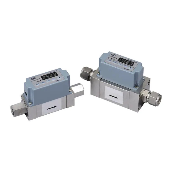
Azbil Micro Flow CMS9500 User Manual

Azbil Micro Flow CMS9500 User Manual

Gas mass flow meter

Advertisement

No. CP-SP-1189E
TM
Gas Mass Flow Meter
SUS/SUS316 Models
CMS9500/0002/0005/
0020/0050/0200/0500
User's Manual
Thank you for purchasing an Azbil
Corporation product.
This manual contains information
for ensuring the correct use of this
product. It also provides necessary
information for installation, main-
tenance, and troubleshooting.
This manual should be read by
those who design and maintain
equipment that uses this product.
Be sure to keep this manual nearby
for handy reference.

Advertisement

Table of Contents
loading
Need help?

Need help?

Do you have a question about the Micro Flow CMS9500 and is the answer not in the manual?

Questions and answers

Summary of Contents for Azbil Micro Flow CMS9500

  • Page 1 No. CP-SP-1189E Gas Mass Flow Meter SUS/SUS316 Models CMS9500/0002/0005/ 0020/0050/0200/0500 User's Manual Thank you for purchasing an Azbil Corporation product. This manual contains information for ensuring the correct use of this product. It also provides necessary information for installation, main- tenance, and troubleshooting.
  • Page 2 If you should find an error or omission, please contact the azbil Group. In no event is Azbil Corporation liable to anyone for any indirect, special or consequential damages as a result of using this product. © 2006-2019 Azbil Corporation. All Rights Reserved.
  • Page 3 Conventions Used in This Manual „ To prevent injury to the operator and others, and to prevent property damage, the following types of safety precautions are indicated: Warnings are indicated when mishandling this product might WARNING result in death or serious injury. Cautions are indicated when mishandling this product might result CAUTION in minor injury to the user, or physical damage to the product.
  • Page 4: Safety Precautions

    Safety Precautions WARNING When using a combustible gas, install the device upstream of the safety shutoff valve. If air or oxygen somehow enters the piping, resulting in an explosive mixture, and the sensor makes a spark due to some cause like a lightning strike, an explosion could occur inside the pipe.
  • Page 5 CAUTION When installing, fasten firmly to prevent vibration. If using Rc connections, take care not to coat with too much sealant. Foreign mat- ter or burrs in the pipes may cause measurement error. Before connecting pipes with Swagelok or VCR connections, check the instructions in the manual provided by the connecting joint manufacturer.
  • Page 6: The Role Of This Manual

    There are two different manuals related to SUS/SUS316 models of CMS/CMF High-Flow Mass Flow Meters. Read them as necessary for your specific requirements. If a manual you require is not available, contact the azbil Group or its dealer. Gas Mass Flow Meter SUS/SUS316 Models CMS 9500/0002/0005/ 0020/0050/0200/0500 User's Manual Document No.
  • Page 7: Table Of Contents

    Contents Conventions Used in This Manual Safety Precautions The Role of This Manual Chapter 1. Overview „ Overview ..........1 „...
  • Page 9: Chapter 1. Overview

    „ Overview SUS/SUS316 models of CMS 9500/0002/0005/0020/0050/0200/0500 Gas Mass Flow Meters measure mass flow by means of a Micro Flow thermal mass flow sensor (hereafter, μF sensor) developed by Azbil Corporation Integrating the µF sensor with advanced channel design technology has achieved high accuracy and high rangeability.
  • Page 10: X84; Model Selection Guide

    Chapter 1. Overview „ Model selection guide z SUS model Example: CMS9500BSRN200000 Basic Flow Gas-con- Con- Out- Option Option Option Option Appended model rate Model tacting nection Description type range material method Gas mass flow meter 9500 0–500 mL/min (standard)* 0002 0–2 L/min (standard)* 0005...
  • Page 11 Chapter 1. Overview z SUS 316 model Basic Flow Gas-con- Con- Out- model rate Model tacting nection pend- Description type tion 1 tion 2 tion 3 tion 4 range material method ed No. Gas mass flow meter 9500 0–500 mL/min (standard)* 0002 0–2 L/min (standard)* 0005...
  • Page 12 Chapter 1. Overview z Optional parts (sold separately) Product Model No. Description Harness with dedicated 81446594-005 For non-communication models, 2 m harness (8-core) connector (One harness is without crimp terminals required for one CMS unit.) 81446594-006 For non-communication models, 5 m harness (8-core) without crimp terminals 81446594-007 For communication models, 2 m harness (10-core) with M3.5 spade terminals...
  • Page 13: Chapter 2. Names And Functions Of Parts

    Chapter 2. Names and Functions of Parts EV1 and EV2 indicators: Lit when event output is generated. Flow rate display: Shows the ow rate using a 4-digit 7-segment LED. During setup, the rst two digits and the last two Instantaneous ow digits show the function and the setting respectively.
  • Page 14: Chapter 3. Mounting And Wiring

    Chapter 3. Mounting and Wiring WARNING When using combustible gas, install the device upstream of the safety shutoff valve. If air somehow enters the piping, resulting in an explosive mixture, and the sensor makes a spark due to some cause like a lightning strike, an explosion could occur inside the pipe. Never allow a gas that is within explosive limits to pass through this device.
  • Page 15: X84; Installation

    Chapter 3. Mounting and Wiring CAUTION Observe the following when using this flowmeter for oxygen gas: • Piping should be done by a specialist experienced in handling oxygen gas, observing general precautions related to oxygen gas. • Use degreased pipes and parts. •...
  • Page 16: X84; Piping

    Metallic mesh Spacers z Filter installation • For a dedicated filter, contact the azbil Group. • For applications with compressed air or propane, which regularly contain oil mist, or applications where rust in the piping is expect- ed, be sure to install a filter. Recommended type:...
  • Page 17 Chapter 3. Mounting and Wiring z Straight pipe length If the flowmeter and the pipe have different internal diameters (diameters A and B are different), a straight pipe section is required. Upstream expansion Downstream reduction Di erent diameter socket, etc. Di erent diameter socket, etc.
  • Page 18 Chapter 3. Mounting and Wiring z Rc connection • Coating sealant Coat the pipe threads, except the two nearest the tip, with an appro- priate amount of sealant. Remove dirt or burrs from the inside of the pipe. Right Wrong Sealant Sealant •...
  • Page 19: X84; Installing The Flowmeter

    Chapter 3. Mounting and Wiring „ Installing the flowmeter CAUTION Mount this device horizontally. If it is mounted vertically, drift may occur when the flow rate is zero, resulting in an erroneous measurement. Do not mount with the top surface facing down. Doing so might cause measurement error or device failure.
  • Page 20 Chapter 3. Mounting and Wiring (2) Mount the flowmeter on the dedicated mounting bracket, and then attach the bracket with four screws from the top of the bracket. Mounting bracket model number 81446628-001: For CMS9500/0002/0005/0020/0050 81446721-001: For CMS0200 81446856-001: For CMS0500 Hole dimensions when mounting bracket is used Unit: mm CMS9500/0002/0005/0020/0050...
  • Page 21: X84; Wiring

    Chapter 3. Mounting and Wiring „ Wiring CAUTION When using a relay as the contact for totalized flow count reset input, use a relay designed for minute currents (with gold contacts). Failure to do so could cause faulty contact, resulting in malfunction. If there is a risk of a power surge caused by lightning, use a surge absorber (surge protector).
  • Page 22 Chapter 3. Mounting and Wiring z Connector signal names Pin No. Signal Description Notes DC OUT+ Instantaneous flow rate positive output DC OUT- Instantaneous flow rate negative output Power + (12 to 24 V DC) Power GND For RS-485 communications Connect only when an RS-485 model is used.
  • Page 23 Chapter 3. Mounting and Wiring z Wiring for inputting totalizer pulse output into a counter • Non-voltage input type Input Counter EV COM • Voltage input type Pull-up resistor 30 V DC or less Input Counter EV COM z Wiring for using flow rate serial data output •...
  • Page 24: Chapter 4. Operation

    Chapter 4. Operation CAUTION Do not operate the console keys using a sharp object such as a mechanical pencil or screwdriver. Doing so might damage the console. Make sure that the selected analog output type matches the input type of the receiving device.
  • Page 25: X84; Function Setup

    Chapter 4. Operation „ Function setup • To enter the setup mode, press the [MODE] key. The first two digits on the display will begin blinking. The first two digits show the function setup item No., and the last two digits show the setting. •...
  • Page 26 Chapter 4. Operation z Function setup menu Function Default Function Setting Description Notes setup setting Key lock When the key lock is ON, function set- tings and parameters can be checked, but cannot be changed. Measurement mode Measure the instantaneous flow rate only.
  • Page 27 Chapter 4. Operation Function Function Setting Description Default setting Notes setup Low flow cutoff No low flow cutoff If the gas type is set to 08 (user Below the minimum displayed specified), the low flow cutoff point flow rate* is the set value multiplied by the 1 % FS CF .
  • Page 28 Chapter 4. Operation *3. The user can specify the desired gas conversion factor to handle gas mixtures and gases other than standard compatible ones. For details regarding gas conversion factors, contact the azbil Group. *4. Changing the gas type and changing the gas type conversion factor ( P-08 ) affect the opera- tion of analog output scaling differently.
  • Page 29: X84; Parameter Setup

    Chapter 4. Operation „ Parameter setup If the key lock is ON, parameters cannot be changed. Press the [ENT] key and [▼] key for 3 seconds or longer to change to parameter setup mode. If the function setup item does not relate to any parameters, P--- will be displayed.
  • Page 30 Chapter 4. Operation z CMS9500 Condition for display (setting Parameter Item Default setting Setting range in function setup mode) Event output 1 (EV1) 0 to 9999 (mL/min) 03 is set to 0 1, or 02. P-0 1 0 to 99999999 (× 10mL) 03 is set to 03 or 04 00000000.
  • Page 31 Chapter 4. Operation z CMS0020/0050 Condition for display (setting Parameter Item Default setting Setting range in function setup mode) Event output 1 (EV1) 0 to 999.9 (L/min)* 03 is set to 0 1, or 02. P-0 1 0 to 99999999 (L) 03 is set to 03 or 04.
  • Page 32: X84; Display Off Mode

    Chapter 4. Operation „ Display OFF mode If the [DISP] key is pressed for at least three seconds, only the instan- taneous flow rate indicator will begin blinking, and the rest of the display will turn off. If the [DISP] key is pressed in display OFF mode, the instantaneous flow rate will be displayed.
  • Page 33: X84; Event On-Delay

    Chapter 4. Operation „ Event ON-delay An ON-delay time (0 to 60 s) can be set for both events 1 and 2. Event output -delay time Event ON Instantaneous ow rate Time Event detection „ Zero flow rate calibration When the indicated flow rate is not zero even though the actual flow rate is zero, if an incorrect sensor zero point is likely to be causing the problem, execute zero flow rate calibration as shown below.
  • Page 34: Chapter 5. Troubleshooting

    • Check if the gas contains oil, moisture, or a foreign substance such as dust or rust. rate is lower than If foreign matter is found in the piping, flow path, etc., contact the azbil Group and ask expected. for repair.
  • Page 35 -MEMO-...
  • Page 36: Chapter 6. Specifications

    Horizontal mounting. (The display unit should not face downward.) If this device is mounted vertically, drift may occur due to the mounting orientation when the flow rate is zero. For details, contact the azbil Group. Rated voltage 12 to 24 V DC Supply voltage range 11.4 to 25.2 V DC...
  • Page 37 Horizontal mounting. (The display unit should not face downward.) If this device is mounted vertically, drift may occur due to the mounting orientation when the flow rate is zero. For details, contact the azbil Group. 12 to 24 V DC 11.4 to 25.2 V DC...
  • Page 38 Weight Approx. 800 g *1. Gas types other than those listed above can be handled by using a conversion factor. For details, contact the azbil Group. *2. For fuel gas 13A, the device is calibrated based on the following two types of gases. If the composition of the fuel gas that you use does not match either of these types, please contact Azbil Corporation.
  • Page 39 Chapter 6. Specifications CMS0020 CMS0050 CMS0200 CMS0500 4-digit 7-segment LED (the instantaneous flow rate and totalized flow displays can be switched) 0.1 L/min (0.05 L/min)* 0.1 L/min 1 L/min (0.5 L/min)* 1 L/min 0.1 L/min (0.05 L/min)* 0.1 L/min 1 L/min (0.5 L/min)* 1 L/min 10 L 0 to 99999999...
  • Page 40 Chapter 6. Specifications z Maximum measurable flow rate and output voltage for various gas types The tables below show output corresponding to the maximum mea- surable flow rate when 0–5 V analog output scaling is selected. CMS9500 CMS0002 Maximum mea- Setting and dis- Maximum mea- Setting and dis-...
  • Page 41: X84; Korea Certification Mark

    Chapter 6. Specifications CMS0050 CMS0200 Maximum mea- Setting and dis- Maximum mea- Setting and dis- Gas type Output voltage Output voltage surable flow rate play resolution surable flow rate play resolution [L/min] [L/min] [L/min] [L/min] Air/nitrogen Argon Carbon dioxide (CO Oxygen* Fuel gas 13A 3.75...
  • Page 42: X84; External Dimensions

    L/min X10L DISP MODE Connector*: DF11-10DP-2DS, Mounting bracket made by Hirose Electric Co., Ltd. (4.5) Azbil Corporation MADE IN JAPAN 18.5 15.7 15.7 Connection threads : Rc 1/4 (2) M4 threaded holes (2), 5 mm deep (for retaining screws) *Optional part (sold separately) Harness with dedicated connector: model No.
  • Page 43 MODE Mounting Mounting bracket: bracket model No. 81446721-001 Connector*: DF11-10DP-2DS, made by Hirose Electric Co., Ltd. Azbil Corporation MADE IN JAPAN 16.4 16.4 Connection thread: Rc 1/2 (2) 98.6 M5 threaded holes (4), 8 mm deep (for retaining screws) 80 0.3...
  • Page 44 L/min X10L DISP MODE Mounting bracket (4.5) Connector*: DF11-10DP-2DS, made by Hirose Electric Co., Ltd. Azbil Corporation MADE IN JAPAN 2-3/4-16 UNF 18.7 18.7 3/4-16 UNF connection type 98.6 M4 threaded holes (4), 6 mm deep (for retaining screws) Azbil Corporation...
  • Page 45 Mass Flow Meter L/min X10L DISP MODE Mounting bracket Connector*: DF11-10DP-2DS, made by Hirose Electric Co., Ltd. Azbil Corporation MADE IN JAPAN 3/4-16 UNF connection type (standard) 16.4 16.4 2-3/4-16 UNF 98.6 M5 threaded holes (4), 8 mm deep (for retaining screws)
  • Page 46 Chapter 6. Specifications z Harness with dedicated connector 81446594-ITEM ITEM: 005, 006 No. of ITEM L (mm) wire 2000 +250 5000 2000 5000 +250 ITEM: 007, 008 z 81446957-001 AC adapter 1800 Note The 81446594-030 AC adapter connection harness is necessary when supplying AC power to the CMS.
  • Page 47 Chapter 6. Specifications z Mounting bracket, 81446628-001 (for CMS9500/0002/0005/0020/0050) Material: SUS304 Unit: mm 13.5 Mounting hole for SUS models A (4 places) Mounting hole for resin models B (2 places) z Mounting bracket, 81446721-001 (for CMS0200) Material: SUS304 Unit: mm A (4 places) z Mounting bracket, 81446856-001 (for CMS0500) Material: SUS304...
  • Page 48: X84; Pressure Loss

    Chapter 6. Specifications „ Pressure loss The graphs below show the data for air. If a gas other than air is used, multiply by the specific gravity in the table below. Specific gravity (with air as 1.0) Argon 1.38 Carbon dioxide (CO 1.53 Oxygen 1.11...
  • Page 49 Chapter 6. Specifications CMS0002 50.0 Primary pressure 45.0 0.5 kPa 40.0 100 kPa 300 kPa 35.0 500 kPa 30.0 700 kPa 25.0 20.0 15.0 10.0 Flow rate (L/min, standard) CMS0005 180.0 Primary pressure 160.0 0.5 kPa 140.0 100 kPa 300 kPa 120.0 500 kPa 700 kPa...
  • Page 50 Chapter 6. Specifications CMS0050 800.0 Primary pressure 700.0 1 kPa 100 kPa 600.0 300 kPa 500.0 500 kPa 700 kPa 400.0 300.0 200.0 100.0 Flow rate (L/min, standard) CMS0200 800.0 Primary pressure 700.0 1 kPa 600.0 100 kPa 300 kPa 500.0 500 kPa 400.0...
  • Page 51 Revision History of CP-SP-1189E Printed Edn. Revised pages Description Dec. 2006 Apr. 2012 Company name changed. Oct. 2019 The manual name was changed. “City gas” and “natural gas” were changed to “fuel gas. ” Inside front cover IMPORTANT notice was added. i, 1, “CMS Series flowmeter”...
  • Page 52 Specifications are subject to change without notice. (11) 1-12-2 Kawana, Fujisawa Kanagawa 251-8522 Japan 1st edition: Dec. 2006 (U) URL: https://www.azbil.com 3rd edittion: Oct. 2019 (V)

Table of Contents