Table of Contents
Advertisement
Quick Links
No. CP-SP-1190E
TM
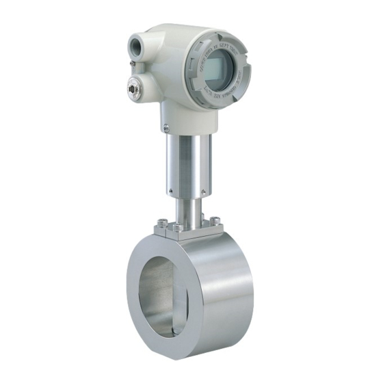
MVF Series
Micro Flow Vortex Gas Flowmeter
User's Manual
Thank you for purchasing an MVF Series
flowmeter.
This manual contains information for
ensuring the correct use of the MVF
Series flowmeter. It also provides nec-
essary information for installation,
maintenance, and troubleshooting.
This manual should be read by those
who design and maintain equipment
that uses the MVF Series flowmeter. Be
sure to keep this manual nearby for
handy reference.
Advertisement
Table of Contents

Related Manuals for Azbil mF MVF Series


Summary of Contents for Azbil mF MVF Series
- Page 1 No. CP-SP-1190E MVF Series Micro Flow Vortex Gas Flowmeter User's Manual Thank you for purchasing an MVF Series flowmeter. This manual contains information for ensuring the correct use of the MVF Series flowmeter. It also provides nec- essary information for installation, maintenance, and troubleshooting.
- Page 2 RESTRICTIONS ON USE This product has been designed, developed and manufactured for general-purpose application in machinery and equipment. Accordingly, when used in applications outlined below, special care should be taken to implement a fail-safe and/or redundant design concept as well as a periodic maintenance program.
-
Page 3: Safety Precautions
SAFETY PRECAUTIONS ■ About Icons The safety precautions described in this manual are indicated by various icons. Please be sure you read and understand the icons and their meanings described below before reading the rest of the manual. Safety precautions are intended to ensure the safe and correct use of this prod- uct, to prevent injury to the operator and others, and to prevent damage to proper- ty. - Page 4 WARNING If this device is used with flammable gases such as natural gas, propane or butane, mount it on the upstream side of the safety shutoff valve. When air gets in the pipe and an explosive mixture is produced, and if a sensor should make a spark due to lightning or other reasons, the mix- ture may explode inside the pipe.
- Page 5 CAUTION This device is a precision instrument. Do not drop it or subject it to shock. Doing so might damage the device. When connecting flanges, tighten with the specified torque. Otherwise gas could leak from the pipe, causing injury. When mounting the device, firmly fasten to prevent vibration. Do not peel off the pipe connector port seals until immediately before you connect the piping.
-
Page 6: Organization Of This User's Manual
Organization of This User's Manual This manual is organized as follows: Chapter 1. INTRODUCTION This chapter describes features on this device. Chapter 2. NAMES AND FUNCTIONS OF PARTS This chapter describes the NAMES AND FUNCTIONS OF PARTS on this device. Chapter 3. -
Page 7: Table Of Contents
Contents SAFETY PRECAUTIONS Organization of This User's Manual Conventions Used in This Manual Chapter 1. INTRODUCTION ■ Introduction • • • • • • • • • • • • • • • • • • • • • • • • • • • • • • • • • • • • • • • • • • • • • • • • • • • • • • • • • • • • • ■... -
Page 9: Chapter 1. Introduction
Chapter 1. INTRODUCTION ■ Introduction The MVF Series Micro Flow Vortex Gas Flowmeter (hereafter called "the device" or "the MVF") is a thermal vortex gas flowmeter featuring a wide measurement range. It uses the Yamatake-designed Micro Flow sensor (or "µF sensor") as a vor- tex generator. -
Page 10: Model Selection Table
Chapter 1. INTRODUCTION ■ Model selection table The following shows the model Nos. for this flowmeter: Basic Pipe Model Material Connecti- Output Power Commu- Flow and moun- Option 1 Option 2 Appended Descripton model No. size type on method type nication ting direction Micro Flow Vortex Flowmeter... -
Page 11: Chapter 2. Names And Functions Of Parts
Chapter 2. NAMES AND FUNCTIONS OF PARTS ■ Body Converter Label Terminal housing cover Wiring connection port Display Terminal block Gauge pressure sensor A-A cross-section of flow passage Flow direction µF sensor µF sensor Pipe connector (wafer) Vortex generator Display Used for the display of instantaneous flow rate, integrated flow rate, and alarm status and error of this device. -
Page 12: Display
Chapter 2. NAMES AND FUNCTIONS OF PARTS ■ Display CAUTION Before pressing the reset switch, touch a metal surface such as the housing of the device to discharge static electricity. Reset switch OVER setting m/min 7-segment display upper SCFM kg/h 7-segment display lower Station address setting switch Loader jack... -
Page 13: Chapter 3. Installation, Mounting, Wiring
Chapter 3. INSTALLATION, MOUNTING, WIRING WARNING If this device is used with flammable gases such as natural gas, propane or butane, mount it on the upstream side of the safety shutoff valve. When air gets in the pipe and an explosive mixture is produced, and if a sensor should make a spark due to lightning or other reasons, the mixture may explode inside the pipe. -
Page 14: Installation
Chapter 3. INSTALLATION, MOUNTING, WIRING ■ Installation Avoid mounting this device in the following locations: • Locations whose ambient temperature falls below -15˚C and rises above +60˚C • Locations whose ambient humidity exceeds 90%RH • Locations subject to sudden changes in temperature and condensation •... - Page 15 Chapter 3. INSTALLATION, MOUNTING, WIRING • Provide a straight pipe section in upstream side and downstream side of the installation location. Refer to the drawings below for the length of upstream pipe section. D indicates the connecting port size. Secure the length of more than 5D for the downstream pipe section.
- Page 16 Chapter 3. INSTALLATION, MOUNTING, WIRING • Do not install at a location receiving the influence of pulsating flow. Handling Precautions • Do not install this device at the location near the exit of compressor. At the location near the exit of compressor the strong pulsating flow is caused and there might be a dispersing of iron powder depending on the compressor type, there is a possibility of causing faulty operation.
-
Page 17: Piping Work
Chapter 3. INSTALLATION, MOUNTING, WIRING ■ Piping work WARNING The mass of this device is 7 to 23kg according to the model number. Ensure to take complete precautions and care while handling for transportation or installation. For safe handling, two or more persons are required while handling this device. - Page 18 Chapter 3. INSTALLATION, MOUNTING, WIRING ● Flange shape Use a flange which can secure a large contacting area with a gasket. Good example Bad example Flange gasket (As the contacting area Welded Welded with a gasket is small, portion portion there is a fear of leakage.) Pipe ●...
-
Page 19: Wiring
Chapter 3. INSTALLATION, MOUNTING, WIRING ■ Wiring CAUTION When connecting the load to the output terminals, do not exceed the rated value shown in the specifications. Doing to do so might cause the damage of this device. Before wiring, be sure to turn the power OFF. Before supplying power, be sure to check that there is no wiring error. - Page 20 Chapter 3. INSTALLATION, MOUNTING, WIRING (3) Remove the terminal cover. (4) Put the packing on the supplied waterproof gland. (5) Pass the cable through the waterproof gland, and mount the waterproof gland in the wiring connection port. Handling Precautions • Never remove the packing from the waterproof gland. •...
- Page 21 Chapter 3. INSTALLATION, MOUNTING, WIRING (2) Remove the red cap from the wiring connection port. (3) When leading out the wiring from two ports, remove the plug also. (4) Remove the terminal cover. (5) Connect an electrical wiring conduit. (6) Pass the wiring through the electrical wiring conduit and then connect the wiring to the terminal block.
- Page 22 Chapter 3. INSTALLATION, MOUNTING, WIRING ● Terminal layout Wiring label Terminal Signal Description name RS-485 communication DA RS-485 communication DB Unused Do not use Unused Do not use Pulse output (NPN open collector) Common RS-485 communication common +24V 24V power Common 4 to 20mA output Ground terminal...
-
Page 23: Chapter 4. Troubleshooting
Chapter 4. TROUBLESHOOTING If there is a problem with this device, refer to the table below. ■ Nothing on display Make sure that the correct power voltage being applied and the polarity are correct. Make sure that the electric wires are connected. ■... -
Page 24: Alarm Display
Chapter 4. TROUBLESHOOTING ■ Alarm display If conditions exceed the device's specified range, an alarm message and the instan- taneous value are alternately displayed. In order to use this device within an allow- able range, change the conditions of the fluid. Alarm Cause display... -
Page 25: Chapter 5. Specifications
Chapter 5. SPECIFICATIONS ■ Specifications Specifications Item MVF050 MVF080 MVF100 MVF150 Pipe size 50A (2B) 80A (3B) 100A (4B) 150A (6B) Flowrate measurement 13 to 1280m /h (normal) 29 to 2826m /h (normal) 44 to 4352m /h (normal) 94 to 9364m /h (normal) range (@23°C for air) (at a pressure of 0.5MPa) "Normal"... -
Page 26: Specifying Accuracy
Chapter 5. SPECIFICATIONS ■ Specifying accuracy See the tables for specifying accuracy on pages 20 and following. The accuracy tables show the ranges when the gas is air. To convert to other application condi- tions, calculate as shown below. The Reynolds number (Re) used below is calculated using the formula Re = (V ×... - Page 27 Chapter 5. SPECIFICATIONS /h(normal)) = 5.2 × ((273+0)/(273+23)) × ((101.3+700)/101.3) = 38 Qnormal (m Amount of temperature Amount of pressure compensation compensation Therefore, mass flow rate can be measured starting from a minimum of 38m (normal). 2. Maximum measurable flow rate (volumetric flow rate (m /h) and mass flow rate (m /h (normal)) MVF flowmeters can measure velocity up to 30m/s.
- Page 28 Chapter 5. SPECIFICATIONS With Re = 33139 (flow rate = 0.8m/s), since the velocity is 0.5m/s or more and Re is in the 10000-35000 range, the volumetric flow rate accuracy is ±4% RD. ● Specifying volumetric flow rate accuracy (below) Volumetric flow rate accuracy = 4% RD Temperature accuracy = 2% RD Pressure accuracy = 0.01 / fluid pressure (MPa) = 0.01/0.7 = 1.4% DR...
-
Page 29: Tables For Specifying Volumetric Flow Rate Accuracy (In Air)
Chapter 5. SPECIFICATIONS ■ Tables for specifying volumetric flow rate accuracy (in air) Unit of flow rate: m /h (actual @ 23°C) Accuracy differs according to operating pressure and flow rate ranges. ● MVF050 (Pipe size 50A) ● MVF080 (Pipe size 80A) Operating Minimum Accuracy Operating Minimum... - Page 30 Chapter 5. SPECIFICATIONS ■ Tables for accuracy after temperature and pressure compensation (in air) Unit of flow rate: m /h (actual @ 23°C) Accuracy differs according to operating pressure and flow rate range. ● MVF050 (Pipe size 50A) Operating Minimum mea- pressure surable flow rate Accuracy...
- Page 31 Chapter 5. SPECIFICATIONS ● MVF100 (Pipe size 100A) Operating Minimum mea- pressure surable flow rate Accuracy (MPa) Q min 0.10 14.6 ±Qmin ±6.7% RD ±5.7% RD 14.6 ≤ Q ≤ 39 39 < Q < 156 156 ≤ Q ≤ 1457 0.15 18.2 ±Qmin...
-
Page 32: Pressure Loss
Chapter 5. SPECIFICATIONS ■ Pressure loss MVF050 (Pipe size 50A) MVF080 (Pipe size 80A) MVF100 (Pipe size 100A) MVF150 (Pipe size 150A) ● Inlet pressure 0.01MPa ● Inlet pressure 0.3MPa 600 800 1000 1200 1400 1600 1800 2000 1000 2000 3000 4000 5000... -
Page 33: External Dimensions
Chapter 5. SPECIFICATIONS ■ External dimensions Unit : mm ● MVF050 (Pipe size 50A) φ ● MVF080 (Pipe size 80A) φ... - Page 34 Chapter 5. SPECIFICATIONS ● MVF100 (Pipe size 100A) φ ● MVF150 (Pipe size 150A) φ Eyebolt...
- Page 35 MEMO...
- Page 37 Revision History Printed Manual Number Edition Revised pages Description date CP-SP-1190E 1st Edition Sep. 2005 2nd Edition ii, iii Warning about disassembling added to WARNING Feb. 2006 section.Order of CAUTION items changed. System section: “Integrated pulse output” changed to “Pulse output.” "Rotary switch"...
- Page 39 Specifications are subject to change without notice. Advanced Automation Company 1-12-2 Kawana, Fujisawa Kanagawa 251-8522 Japan Printed in Japan. URL: http://www.azbil.com 1st Edition: Issued in Sep. 2005 (W) 3rd Edition: Issued in June 2007 (B) Printed on recycled paper. (07)
Need help?
Do you have a question about the mF MVF Series and is the answer not in the manual?
Questions and answers