Table of Contents
Advertisement
Quick Links
User's Manual
Smart Loader Package
Model SLP-F7M
Micro Flow Rate Liquid Flow Meter
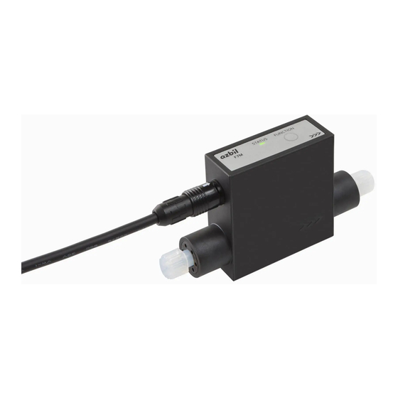
Model F7M
for
for
Thank you for purchasing this Azbil
Corporation product. This manual contains
information for ensuring the correct use of
the smart loader package.
Those designing, configuring, or
maintaining equipment that uses this
product should first read and understand
this manual. It provides necessary
information not only for initial setup,
but also for changing of settings,
troubleshooting, etc. Be sure to keep the
manual nearby for handy reference.
No. CP-SP-1423E
Advertisement
Table of Contents

Subscribe to Our Youtube Channel
Related Manuals for Azbil SLP-F7M


Summary of Contents for Azbil SLP-F7M
- Page 1 User’s Manual Smart Loader Package Model SLP-F7M Micro Flow Rate Liquid Flow Meter Model F7M Thank you for purchasing this Azbil Corporation product. This manual contains information for ensuring the correct use of the smart loader package. Those designing, configuring, or...
- Page 2 If you should find an error or omission, please contact the azbil Group. In no event is Azbil Corporation liable to anyone for any indirect, special or consequential damages as a result of using this product. © 2018-2019 Azbil Corporation. All Rights Reserved.
- Page 3 Conventions Used in This Manual „ „ The safety precautions explained in the following section aim to prevent injury to the operator and others, and to prevent property damage. Warnings are indicated when mishandling this WARNING product might result in death or serious injury. CAUTION Cautions are indicated when mishandling this product might result in minor injury to the user, or...
-
Page 4: Safety Precautions
Safety Precautions CAUTION To use loader communications, remove the cable from the F7M waterproof connector and connect it to the adapter for loader communication cable. When handling the cable, make sure that the electrodes of the connector are free from water drops and dust. Otherwise, a failure or abnormal output might result. -
Page 5: The Role Of This Manual
The Role of This Manual A total of 3 different manuals are available for Model SLP-F7M. Read them as necessary for your specific requirements. If a manual you require is not available, contact the azbil Group or its dealer. User’s Manual for Smart Loader Package Model SLP-F7M for Micro Flow Rate Liquid Flow Meter Model F7M Manual No. -
Page 6: Table Of Contents
Contents Conventions Used in This Manual Safety Precautions The Role of This Manual Chapter 1. INTRODUCTION 1 - 1 Overview Features of the loader „ „ Applicable versions „ „ 1 - 2 System Requirements „ „ System Environment Hardware Configuration „... - Page 7 3 - 7 List of Monitoring Parameters 3-18 [Monitor] tab 3-18 „ „ 3 - 8 Operating the Device 3-20 „ „ Adjusting the zero point 3-20 Chapter 4. TROUBLESHOOTING Types of abnormal status „ „ Abnormal status and corrective actions „...
- Page 8 -MEMO-...
-
Page 9: Chapter 1. Introduction
1 - 1 Overview The SLP-F7M Smart Loader Package (hereafter “the loader”) is a simplified engineering tool for the F7M Micro Flow Rate Liquid Flow Meter (“the device”). The user can configure various settings of the device and monitor the flow rate and the operational status. -
Page 10: System Requirements
A mouse or an equivalent device compatible with Windows. USB port 1 port Other hardware Adapter for loader Adapter for loader communication cable (azbil brand, model No. communication cable F9Y7A1) USB loader cable USB loader cable (azbil brand, model No. 81441177-001)* Cable for waterproof connector Cable (azbil brand, model No. -
Page 11: X84; „ Hardware Configuration
Chapter 1. INTRODUCTION Hardware Configuration „ „ The hardware configuration for loader communication is explained below. „ Connection method • Turn off the supply of power to the device. • Remove the cable from the waterproof connector on the device, and connect the cable to the adapter for loader communication cable with cable B, which is supplied with the adapter. - Page 12 Chapter 1. INTRODUCTION Note • It is also possible, without using cable B, to directly connect the adapter for loader communication cable to the cable removed from the waterproof connector on the device. Handling Precautions • To use loader communications, remove the cable from the device waterproof connector and connect it to the adapter for loader communication cable.
-
Page 13: Installation
Chapter 1. INTRODUCTION 1 - 3 Installation Please download the installer for the loader from the following website (in Japanese only): https://www.compoclub.com/ The installer file is compressed. Expand it before use. (Expanded file name example: setup_SLPSP7_en_V1_0_15.msi) Installing the Loader „ „... - Page 14 Chapter 1. INTRODUCTION >> The following screen is displayed. (3) If you accept the software license agreement and wish to install the software, check the check box for [I accept the terms in the License Agreement] and click the [Next] button. >>...
- Page 15 Chapter 1. INTRODUCTION >> The following screen is displayed. (5) Click the [Install] button. >> When installation is complete, the following screen is displayed. Handling Precautions • A warning message about user account control might appear, depending on the PC settings. Allow the software to make changes to the computer. (6) Click the [Finish] button.
-
Page 16: X84; „ Installing The Usb Loader Cable Device Driver
Chapter 1. INTRODUCTION Installing the USB Loader Cable Device Driver „ „ A device driver must be installed before using the USB loader cable. Follow the procedure below to install the device driver on the PC. Installing the device driver „... - Page 17 Chapter 1. INTRODUCTION >> The installer is launched and the following window is displayed. Handling Precautions • A warning message about user account control might appear, depending on the PC settings. Click the [Yes] button to allow the software to make changes to the computer.
- Page 18 Chapter 1. INTRODUCTION (3) Select the label code A, B, or C of your USB loader cable in the window, and click the [Next] button. >> The following screen is displayed. Handling Precautions • If a message saying that the USB loader cable driver has already been installed on your computer appears even if you uninstalled the driver in the past, follow the procedure described in „...
- Page 19 Chapter 1. INTRODUCTION (5) Click the [Next ] button. >> The following screen is displayed. (6) If you accept the software license agreement and wish to install the software, select [AGREE] and click the [Next] button. >> Installation of the device driver starts and the following window is displayed.
-
Page 20: X84; „ If The Usb Loader Cable Device Driver Cannot Be Installed
Chapter 1. INTRODUCTION (7) Click the [Finish] button. >> The following screen is displayed. (8) Click the [Finish] button. Installation of the device driver is complete. If the USB loader cable device driver cannot be installed „ „ When attempting to install the device driver on a PC on which a USB loader cable was used in the past, the following window may appear, and it may not be possible to install the driver, even if the previous device driver has already been uninstalled. - Page 21 Chapter 1. INTRODUCTION (1) Click the [Next ] button. >> Once the installation process is complete, the following screen is displayed. (2) Click the [Finish] button. >> The installer for the device driver closes. Step 2. Follow the procedure described in „...
-
Page 22: X84; „ Checking And Installing Microsoft .Net Framework
Chapter 1. INTRODUCTION Checking and Installing Microsoft .NET Framework „ „ (1) Right-click the [Start] button and select [Programs and Features]. >> The following screen is displayed. (2) Select [Turn Windows features on or off ]. >> The following screen appears: (3) Check that .NET Framework is enabled. -
Page 23: Uninstallation
(1) Right-click the [Start] button and select [Programs and Features]. >> The following screen is displayed. (2) Double-click “SLP-F7M (F7M) English” under [Name]. >> The following screen is displayed. (3) Click the [Yes] button. The program and related files will be deleted. - Page 24 Chapter 1. INTRODUCTION (1) Right-click the [Start] button and select [Programs and Features]. >> The following screen is displayed. (2) Double-click “Azbil Loader Cable Driver.” >> The following screen is displayed. (3) Click the [Yes] button. >> The device driver is deleted and the following window is displayed.
-
Page 25: Chapter 2. Starting And Exiting The Loader
„ Double-click the [SLP-F7M (F7M) English] icon on the desktop, or click the [Start] button at the bottom left of the screen and select [All Apps] → [SLP] → [SLP-F7M (F7M) English]. >> The following splash screen is displayed for 3 seconds. -
Page 26: X84; „ Exiting The Loader
Chapter 2. STARTING AND EXITING THE LOADER Note • For details on the OS or the mouse, see the user’s manuals provided with those products. „ „ Exiting the loader Select [File] → [Exit] or click the [×] icon in the upper right corner of the screen. >>The loader closes. -
Page 27: Chapter 3. How To Use The Loader
Chapter 3. HOW TO USE THE LOADER 3 - 1 Overview Overview of functions „ „ Connect the loader to the device in order to change the parameters, monitor the flow rate and device status, and for other operations (zero point adjustment, etc.). Parameters and monitoring results can be saved to a file. -
Page 28: X84; „ Loader Functions
Device Zero point adjustment Automatically adjusts the zero point of the instantaneous flow rate. operation Help User's Manual for SLP-F7M The user's manual for the loader can be viewed.* – – Smart Loader Package for F7M (PDF) F7M Micro Flow Rate The user's manual for the device can be viewed.*... -
Page 29: Connecting The Loader To The Device
Chapter 3. HOW TO USE THE LOADER 3 - 2 Connecting the Loader to the Device In order to check or change the data on the device, the loader must first be connected to the device. The procedure for connection is as follows. Steps 1–2: Connect the PC to the device. - Page 30 Chapter 3. HOW TO USE THE LOADER (5) In the COM port field, select the COM number for the USB loader cable, and click the [OK] button. >> The window closes. Note • To identify which of multiple communication ports is used, in Windows select [Control Panel] →...
- Page 31 Chapter 3. HOW TO USE THE LOADER >> If communication activation failed, the following screen is displayed. Click the [End] button. Check the communication settings of the loader, the state of the device, and the connection to the device, and then repeat steps (1)–(8).
-
Page 32: Checking And Changing Parameters
Chapter 3. HOW TO USE THE LOADER 3 - 3 Checking and Changing Parameters Parameters can be checked or changed by the following methods. · Create a parameter file · Open a parameter file · Read all parameters from the device* Changed parameters can be written to the device or saved by the following methods. - Page 33 Chapter 3. HOW TO USE THE LOADER Handling Precautions • The following device information is displayed after a model number is selected. Model No.: The model number selected in the [Select model number] window. (The digits representing the device specifications that do not affect the loader function are displayed with hyphens.) Serial No.: Signal type:...
-
Page 34: X84; „ Checking Parameters Of The Connected Device
Chapter 3. HOW TO USE THE LOADER >> The following screen is displayed. (5) Enter any name in the [File name] field (example: F7M_N1_1.f7m) and click the [Save] button. Note • „ Writing parameters to the device (P. 3-10), „ Saving parameters to a file (P. 3-11) (for opening saved files and writing parameters to the device) Checking parameters of the connected device „... - Page 35 Chapter 3. HOW TO USE THE LOADER >> The following screen is displayed. (4) Click the [OK] button. >> The following screen is displayed. (5) Click the [Parameters] tab and select the item to check in the tree view. >> The following screen is displayed.
-
Page 36: X84; „ Writing Parameters To The Device
Chapter 3. HOW TO USE THE LOADER Writing parameters to the device „ „ This section describes the procedure for writing parameters to the device. After reading parameters to the loader, perform the following operations. Handling Precautions • Parameters cannot be written to the device if the model number of the device is different from the number in the [Device info.] tab. -
Page 37: X84; „ Saving Parameters To A File
Chapter 3. HOW TO USE THE LOADER Saving parameters to a file „ „ Parameters that were read from the device or that were changed can be saved to a file using the following procedure. (1) Select [File] → [Rename and save...] on the menu bar, or click the button on the toolbar. - Page 38 Chapter 3. HOW TO USE THE LOADER (2) Select the parameter file to open (extension: f7m) and click the [Open] button. >> The following screen is displayed. (3) Select a tab and an item in the tree view to check parameter settings. 3-12...
-
Page 39: List Of Parameters
Chapter 3. HOW TO USE THE LOADER 3 - 4 List of Parameters The following tables show the parameters that can be accessed by the loader. Note • F7M Micro Flow Rate Liquid Flow Meter User’s Manual CP-SP-1421E (for details on parameters) [Device info.] tab „... -
Page 40: X84; „ [Parameters] Tab
Chapter 3. HOW TO USE THE LOADER [Parameters] tab „ „ Parameters Unit Description Factory default DI settings DI function – Zero point adjustment Error reset Error reset Liquid type selection* DO settings DO function – Flow rate event 1 Flow rate event 1 Flow rate event 2 Error indication output... -
Page 41: Checking Measured Values And Status
Chapter 3. HOW TO USE THE LOADER 3 - 5 Checking Measured Values and Status Displaying measured values and status of the device „ „ (1) Connect the loader to the device. ( 3 - 2 Connecting the Loader to the Device (P. 3-3)) (2) Obtain device information by executing steps 1 to 4 in „... -
Page 42: Immediate Writing Of Parameters
Chapter 3. HOW TO USE THE LOADER 3 - 6 Immediate Writing of Parameters How to write monitoring parameters to the device immediately „ „ Only when monitoring is in progress, parameters with the [Write] button can be written to the device immediately. (1) Connect the loader to the device. - Page 43 Chapter 3. HOW TO USE THE LOADER The loader starts updating values and information. When monitoring is in progress, “Monitoring” at the bottom left of the screen is displayed in green and the word “Communicating... ” blinks. Under these conditions, monitoring parameters can be written to the device immediately by pressing the [Write] button.
-
Page 44: List Of Monitoring Parameters
Chapter 3. HOW TO USE THE LOADER 3 - 7 List of Monitoring Parameters [Monitor] tab „ „ Factory Parameters Unit Description default Process value Instantaneous mL/min Indicates the value calculated from the measured flow rate signal. – flow rate Abnormal status –... - Page 45 Chapter 3. HOW TO USE THE LOADER Factory Parameters Unit Description default Abnormal Abnormal status – For maintenance – status code code 0 Abnormal status – For maintenance – code 1 Abnormal status – For maintenance – code 2 Abnormal status –...
-
Page 46: Operating The Device
Chapter 3. HOW TO USE THE LOADER 3 - 8 Operating the Device Adjusting the zero point „ „ Note • To reset the zero point of a device with ID code “b” or later to the value at the time when the device was shipped, set [Zero point adjustment 1] and [Zero point adjustment 2] to “0.00”... - Page 47 Chapter 3. HOW TO USE THE LOADER (4) Check that the pipe is full of fluid and that the fluid is not moving, and then click the [OK] button. >> The following window is displayed. >> When zero point adjustment is complete, the following screen is displayed. (5) Pressing the [OK] button returns the display to the original screen.
- Page 48 -MEMO-...
-
Page 49: Chapter 4. Troubleshooting
Chapter 4. TROUBLESHOOTING Types of abnormal status „ „ There are four types of abnormal status of the device: Error, alarm, warning, and information. Abnormal status can be checked by the loader. Abnormal status of the device Description Error An error has a significant impact on the operation of this device. If an error occurs, flow rate measurement stops. - Page 50 Chapter 4. TROUBLESHOOTING Automatic No. Type Description Likely cause Corrective action recovery ✓ Wn Empty (flow path not full) The flow path of this device has Fill the flow path with the fluid. not been full for some time. Flow rate measurement A flow rate measurement error Check for problems in the error...
- Page 51 Chapter 4. TROUBLESHOOTING Automatic No. Type Description Likely cause Corrective action recovery Nonvolatile memory error The data in the device is corrupt. If the error or information – persists after changing the Backup parameter error The data in the backup area is –...
-
Page 52: X84; „ Error Messages And Corrective Actions
The selected file is for a model If a new version of the loader is the loader. available on the Azbil website that is not supported by the (Compo Club), it might be loader, so the file could not be Reading of the file failed. - Page 53 Reading of parameters failed. the loader software from the device] by the loader is specified, so Azbil website (Compo Club), parameters cannot be read install the loader, and try again. from the device. Reading of parameters failed.
- Page 54 Chapter 4. TROUBLESHOOTING Menu Message Description Corrective action [Monitor] → [Start Monitoring could not be started Monitoring could not begin The model number in the monitoring] because the model number of because the model number loader’s device information the device is different from the of the connected device is must be the same as the model number specified by the loader.
-
Page 55: X84; „ Other Troubleshooting
Chapter 4. TROUBLESHOOTING Other troubleshooting „ „ Type Message Description Corrective action Display Values are not displayed properly. If a symbol other than “. ” is set In the Windows settings, select [Control Panel] → [Region] Files cannot be opened. as the decimal point symbol in the Windows settings, the and press the [[Additional... - Page 56 -MEMO-...
- Page 57 Revision History of CP-SP-1423E Date Rev. Revised pages Description Apr. 2018 Description was added. Added “Applicable versions”. Apr. 2019 Added notes to the figure. 1-14 Changed the URL in “Note. ” Changed a screenshot. Added “Handling Precautions. ” 3-7, 3-9 Changed a screenshot.
- Page 58 Specifications are subject to change without notice. (11) 1-12-2 Kawana, Fujisawa Kanagawa 251-8522 Japan https://www.azbil.com 1st edition: Apr. 2018 (V) 2nd edition Apr. 2019 (V)
Need help?
Do you have a question about the SLP-F7M and is the answer not in the manual?
Questions and answers