Table of Contents
Advertisement
Quick Links
Advertisement
Table of Contents

Related Manuals for DFI BW551


Summary of Contents for DFI BW551
- Page 1 BW551 Embedded SBC 3.5” User’s Manual A40910952...
-
Page 2: Copyright
Copyright FCC and DOC Statement on Class B This publication contains information that is protected by copyright. No part of it may be re- This equipment has been tested and found to comply with the limits for a Class B digital produced in any form or by any means or used to make any transformation/adaptation without device, pursuant to Part 15 of the FCC rules. -
Page 3: Table Of Contents
Table of Contents COM Port Connector ........................17 Standby Power LED ........................18 Front Panel Connector ........................18 Copyright ..............2 SATA (Serial ATA) Connector ...................... 19 SATA (Serial ATA) Power Connector ..................19 Trademarks ..............2 LVDS LCD Panel Connector......................20 LCD/Inverter Power Connector .................... -
Page 4: About This Manual
About this Manual Static Electricity Precautions This manual can be downloaded from the website, or acquired as an electronic file included in It is quite easy to inadvertently damage your PC, system board, components or devices even the optional CD/DVD. The manual is subject to change and update without notice, and may be before installing them in your system unit. -
Page 5: About The Package
About the Package The package contains the following items. If any of these items are missing or damaged, please contact your dealer or sales representative for assistance. • One BW551 board • One COM port cable (Length: 300mm) • One Serial ATA data cable (Length: 500mm) •... -
Page 6: Chapter 1 - Introduction
Operating: 10 to 90% RH Triple VGA + LVDS + DP++ Storage: 10 to 90% RH Displays MTBF BW551 : 411,490 hrs @ 25°C; 250,359 hrs @ 45°C ; 160,650 hrs @ 60°C EXPANSION Interface 1 x Half-size Mini PCIe (PCIe/USB) MECHANICAL Dimensions 3.5"... -
Page 7: Features
USB 1.1 (12Mb/s). USB 3.0 reduces the time required for data transmission, reduces power consumption, and is backward compatible with USB 2.0. It is a marked improvement in device transfer speeds between your computer and a wide range of simultaneously accessible external Plug and Play peripherals. Chapter 1 Introduction www.dfi.com... -
Page 8: Chapter 2 - Hardware Installation
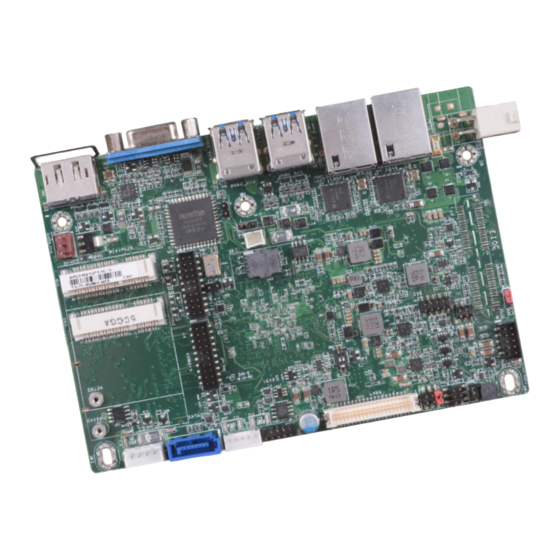
Standby NCT6106D Power LED COM 1/COM 2 COM 3/COM 4 SATA 3.0 DDR3L SODIMM Chrontel CH7517 SATA 0 Fintek Fintek F81437 F81439 SATA Power Fintek Fintek F81439 F81437 DP++ System Fan Top View Bottom View Chapter 2 Hardware Installation www.dfi.com... -
Page 9: Block Diagram
SIM (Opt.) Family 101.72 USB 2.0 USB 2x HD Audio (Line-out, Mic-in) 83.01 SMBus Digital I/O 8-bit 66.41 SMBus LPC Bus TPM (Opt.) 40.92 RS-232/422/485 2x Super IO RS-232 2x with WDT H/W Monitor 11.76 Chapter 2 Hardware Installation www.dfi.com... -
Page 10: System Memory
2. Set JP7 pins 2 and 3 to On. Wait for a few seconds and set JP7 back to its default setting, Features pins 1 and 2 On. 3. Now plug the power cord and power-on the system. • One 204-pin SODIMM up to 8GB • Single Channel DDR3L 1600MHz Chapter 2 Hardware Installation www.dfi.com... -
Page 11: Auto Power-On Select
Before powering-on the system, make sure that the power settings of JP10 match the occurs, the system may not power on if the power lost is resumed within 5 seconds (power power specification of backlight control. Selecting the incorrect voltage will seriously flicker). damage the backlight. Chapter 2 Hardware Installation www.dfi.com... -
Page 12: Panel Power Select
Switch 1 allows you to select the LVDS channel and the color of bits per pixel. Important: Before powering-on the system, make sure that the power settings of JP8 match the LCD panel’s specification. Selecting the incorrect voltage will seriously damage the LCD panel. Chapter 2 Hardware Installation www.dfi.com... -
Page 13: Rear Panel I/O Ports
The 4-pin right-angle connector on the system board co-lays with a DC-in jack (optional) or 4-pin vertical type connector (optional) as the photo displayed below. 4-pin Vertical Type (optional) 4-pin Right Angle DC-in (optional) (default) Chapter 2 Hardware Installation www.dfi.com... -
Page 14: Graphics Interfaces
VESA, delivers higher performance features than any other digital interfaces. Install the LAN drivers. Refer to Chapter 4 for more information. Driver Installation Install the graphics driver. Refer to Chapter 4 for more information. Chapter 2 Hardware Installation www.dfi.com... -
Page 15: Usb Ports
USB port cables to a connector. BIOS Setting Configure the onboard USB in the Advanced menu (“USB Configuration” submenu) of the BIOS. Refer to Chapter 3 for more information. Chapter 2 Hardware Installation www.dfi.com... -
Page 16: I/O Connectors
The front audio connector allows you to connect to the second line-out and mic-in jacks that Pins Function are at the front panel of your system. DIO7 Driver Installation DIO6 Install the audio driver. Refer to the Chapter 4 for more information. DIO5 DIO4 DIO3 DIO2 DIO1 DIO0 Chapter 2 Hardware Installation www.dfi.com... -
Page 17: Com (Serial) Ports
Make sure the colored stripe on the ribbon cable is aligned with pin 1 of the COM connector. BIOS Setting Configure the serial COM ports in the Advanced menu (“Super IO Configuration” submenu) of the BIOS. Refer to the Chapter 3 for more information. Chapter 2 Hardware Installation www.dfi.com... -
Page 18: Standby Power Led
On Suspend) state, it will blink every second. When the system is in the S3 (STR - Suspend To RAM) state, it will blink every 4 seconds. Pin Pin Assignment Pin Pin Assignment HDD_LED Reset Button RESET- HDD-LED SUS_LED Power Button PWR-BTN PWR-LED V_LED Chapter 2 Hardware Installation www.dfi.com... -
Page 19: Sata (Serial Ata) Connector
SATA power connector and the other end to your storage device. BIOS Setting Configure the Serial ATA drive in the Advanced menu (“SATA Configuration” submenu) of the BIOS. Refer to Chapter 3 for more information. Chapter 2 Hardware Installation www.dfi.com... -
Page 20: Lvds Lcd Panel Connector
Configure the LCD panel in the Advanced menu (“Video Configuration” sub- menu ) of the BIOS. Refer to Chapter 3 for more information. Note: DFI board's LVDS connector: Hirose DF13-40DP-1.25V(91)/40P/1.25mm; cable side connector: Hirose DF13-40DS-1.25C. Chapter 2 Hardware Installation www.dfi.com... -
Page 21: Expansion Slot
The mSATA port supports SATA III (6Gb/s) transmission rate and is used to connect an mSATA card. It can expand the system’s storage capacity. SIM Slot (optional) The SIM slot on the system board is used to insert a SIM card. Chapter 2 Hardware Installation www.dfi.com... -
Page 22: Smbus Connector
When the system’s power is off and a chassis intrusion occurred, the alarm will sound only when the system restarts. Chapter 2 Hardware Installation www.dfi.com... -
Page 23: Battery
Safety Measures • Danger of explosion if battery incorrectly replaced. • Replace only with the same or equivalent type recommend by the manufacturer. • Dispose of used batteries according to local ordinance Chapter 2 Hardware Installation www.dfi.com... -
Page 24: Chapter 3 - Bios Setup
When ““ appears on the left of a particular field, it indicates that a submenu which contains additional options are available for that field. To display the submenu, move the highlight to that field and press <Enter>. Chapter 3 BIOS Setup www.dfi.com... -
Page 25: Insyde Bios Setup Utility
Main Advanced Security Boot Exit This is the help for the Project Name BW551 X64 hour, minute, second BIOS Version 64.26A field. Valid range is from 0 to 23, 0 to 59, 0 to 59. Processor Type Intel(R) Celeron(R) CPU N3060 @ 1.60GHz... - Page 26 TDP. Note: For the “After G3” setting to take effect, make sure that the "AC Power Loss” op- tion is set to “Always on” in “SIO NUVOTON6106D” of the “Advanced” menu. Chapter 3 BIOS Setup www.dfi.com...
- Page 27 <24 Bit> Dimming Control <PWM Mode> LCD Panel Type 800x480 800x600 1024x768 1366x768 1280x1024 1920x1080 Help ↑/↓ Select Item F5/F6 Change Values Setup Defaults Exit ←/→ Select Item Enter Select SubMenu Save and Exit Chapter 3 BIOS Setup www.dfi.com...
- Page 28 Setup Defaults Exit ←/→ Select Item Enter Select SubMenu Save and Exit Audio Controller Set to enable or disable the onboard Azalia controller. Disabled Azalia will be unconditionally disabled. Enabled Azalia will be unconditionally enabled. Chapter 3 BIOS Setup www.dfi.com...
- Page 29 AHCI Mode This option allows the Serial ATA devices to use AHCI (Advanced Host Controller Inter- face). Serial ATA Port 0, and 1 This field is used to enable or disable the serial ATA port. Chapter 3 BIOS Setup www.dfi.com...
- Page 30 Enable or disable the PCI Express Root Port. PCIe Speed Select the speed of the PCI Express Root Port: Gen1 or Gen2. Help ↑/↓ Select Item F5/F6 Change Values Setup Defaults Exit ←/→ Select Item Enter Select SubMenu Save and Exit Chapter 3 BIOS Setup www.dfi.com...
- Page 31 Configure the settings to use the serial port. Disable Disable this serial port. Enable Enable this serial port. Type Choose RS232/RS422/RS485 (Peer-to-Peer) for the serial port type for COM port 1 and COM port 2. Chapter 3 BIOS Setup www.dfi.com...
- Page 32 Set the AC power loss to Always off or Always on. When set to Always off, the system’s status will be power-off after an AC power loss event. When set to Always on, the system’s status will be power-on after an AC power loss event. Chapter 3 BIOS Setup www.dfi.com...
-
Page 33: Security
Set the fan speed. The range is from 0 (fan stop)-100% (full speed). Remove all TPM ownership contents. Set Supervisor Password Set the administrative password and the length of the password must be greater than one character. Chapter 3 BIOS Setup www.dfi.com... -
Page 34: Boot
Select this field and then press <Enter>to exit the system setup without saving your changes. PXE Boot Capability Disables or enables PXE boot to LAN. USB Boot Enable or disable the booting to USB boot devices. Chapter 3 BIOS Setup www.dfi.com... -
Page 35: Updating The Bios
Insyde H20FFT (Flash Firmware Tool) Version (SEG) 100.00.08.10 Copyright(c) 2012 - 2016, Insyde Software Corp. All Rights Reserved. Initializing Current BIOS Model name: BW551 New BIOS Model name: BW551 Current BIOS version: 65.05A New BIOS version: 65.05A Updating Block at FFFFF000h... -
Page 36: Chapter 4 - Supported Software
Install drivers, utilities and software applications that are required to facilitate and enhance the performance of the system board. You may acquire the software from your sales representa- tives, from an optional DVD included in the shipment, or from the website download page at https://www.dfi.com/DownloadCenter. For Windows 10 Chapter 4 Supported Software... - Page 37 To install the utility, click “Intel Chipset Software Installation Utility” on the main menu. 1. Setup is ready to install the utility. Click Next. 2. Read the license agreement then click Yes. Note: This step can be ignored if the applications are standalone files. Chapter 4 Supported Software www.dfi.com...
- Page 38 1 to 2 minutes (while WinSAT is running) before the Windows 7/Windows 8.1/Windows 10 desktop appears. The “blank screen” period is the time Windows is testing the graphics performance. 2. Read the license agreement then click Yes. Chapter 4 Supported Software www.dfi.com...
- Page 39 Restarting the system will allow the new software installation to take effect. 5. Click “Yes, I want to restart this computer now” then click Finish. Restarting the system will allow the new software installation to take effect. Chapter 4 Supported Software www.dfi.com...
- Page 40 1. Setup is ready to install the driver. Click Next. 5. After completing installa- tion, click Finish. 2. Click “I accept the terms in the license agreement” then click “Next”. 3. Select the program featuers you want installed then click Next. Chapter 4 Supported Software www.dfi.com...
- Page 41 3. Click “Restart Now“ to restart your computer when the installation is complete. To install the driver, click “Kernel Mode Driver Framework” on the main menu. 1. Click “Yes“ to install the update. 2. The update is installed now. Chapter 4 Supported Software www.dfi.com...
- Page 42 1. Tick “I accept the terms in the License Agreement“ and then click “Next.” 4. Click “Finish“ when the installation is complete. 2. The step shows the components which will be installed. Then, Click Next. Chapter 4 Supported Software www.dfi.com...
- Page 43 1. Setup is ready to install the driver. 4. The wizard is ready to begin installation. Click “Install”. 2. Click “Next” to continue. 5. Please wait while the program features are being installed. Chapter 4 Supported Software www.dfi.com...
- Page 44 The screenshot displayed above is for illustrative purpose only, and may not resemble the actual screen. The BW551 HW Utility features the following tabs: Information, HW Health, HW Health set, Watchdog, DIO and Backlight. Click on the tabs to access information about the board.
- Page 45 4. Setup is currently installing the driver. After installation has com- pleted, click Next. 2. Read the license agreement care- fully. Click “I accept the terms in the cense Agreement” then click Next. 5. After completing installation, click Finish. Chapter 4 Supported Software www.dfi.com...
- Page 46 Chapter 4 3. Read the file information then click 5. Setup is now installing the Next. driver. 4. Setup is ready to install the driver. 6. Click Finish. Click Next. Chapter 4 Supported Software www.dfi.com...
- Page 47 To install the reader, click “Adobe Acrobat Reader 9.3” on the main menu. 1. Click Next to install or click Change Destination Folder to select another folder. 2. Click Install to begin installa- tion. 3. Click Finish to exit installation. Chapter 4 Supported Software www.dfi.com...
-
Page 48: Appendix A - System Error Message
The BIOS reports memory test fail if the memory has error(s). FLOPPY DISK(S) fail (80) Unable to reset floppy subsystem. FLOPPY DISK(S) fail (40) Floppy type mismatch. Hard Disk(s) fail (80) HDD reset failed. Hard Disk(s) fail (40) HDD controller diagnostics failed. Appendix A System Error Message www.dfi.com... -
Page 49: Appendix B - Troubleshooting Checklist
4. There is not enough space left on the diskette. Use another diskette with adequate storage 4. Adjust the brightness of the display by turning the monitor’s brightness control knob. space. Appendix B Troubleshooting Checklist www.dfi.com... - Page 50 Nothing happens when a key on the keyboard was pressed. 1. Make sure the keyboard is properly connected. 2. Make sure there are no objects resting on the keyboard and that no keys are pressed dur- ing the booting process. Appendix B Troubleshooting Checklist www.dfi.com...
Need help?
Do you have a question about the BW551 and is the answer not in the manual?
Questions and answers