Table of Contents
Advertisement
Quick Links
Advertisement
Table of Contents

Related Manuals for DFI BE170


Summary of Contents for DFI BE170
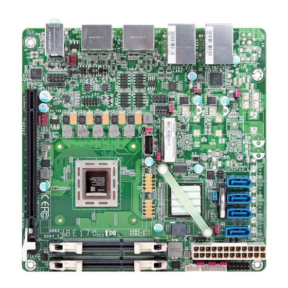
- Page 1 BE170/BE171/BE173 Mini-ITX Industrial Motherboard User’s Manual A35200522...
-
Page 2: Copyright
Copyright FCC and DOC Statement on Class B This publication contains information that is protected by copyright. No part of it may be re- This equipment has been tested and found to comply with the limits for a Class B digital produced in any form or by any means or used to make any transformation/adaptation without device, pursuant to Part 15 of the FCC rules. -
Page 3: Table Of Contents
Table of Contents ATX Power Connector ................. 24 S/PDIF Connector ..................25 Expansion Slots ..................25 Copyright ......................2 Chassis Intrusion Connector ................ 26 LPC Connector .................... 26 Trademarks ......................2 Standby Power LED ..................27 Battery ....................... 27 FCC and DOC Statement on Class B ............. -
Page 4: About This Manual
About this Manual Static Electricity Precautions An electronic file of this manual is included in the CD. To view the user’s manual in the CD, It is quite easy to inadvertently damage your PC, system board, components or devices even insert the CD into a CD-ROM drive. -
Page 5: About The Package
The package contains the following items. If any of these items are missing or damaged, please contact your dealer or sales representative for assistance. • One BE170/BE171/BE173 motherboard • One Serial ATA data cable - BE170 • One Serial ATA data with power cable - BE171/BE173 • One I/O Shield •... -
Page 6: Chapter 1 - Introduction
• Read back capability that displays temperature, voltage and fan speed • 1 Realtek RTL8111EP Ethernet controller Power • BE170-77EN-427B: 38.06W with RX-427BB at 2.7GHz and 2x 4GB DDR3L - supports DASH for remote management • Integrated 10/100/1000 transceiver SODIMM Consumption •... -
Page 7: Features
Chapter 1 • Wake-On-LAN Features This feature allows the network to remotely wake up a Soft Power Down (Soft-Off) PC. It is • Watchdog Timer supported via the onboard LAN port or via a PCI LAN card that uses the PCI PME (Power Man- agement Event) signal. -
Page 8: Power Failure Recovery
Chapter 1 • USB The system board supports the new USB 3.0. It is capable of running at a maximum transmis- sion speed of up to 5 Gbit/s (625 MB/s) and is faster than USB 2.0 (480 Mbit/s, or 60 MB/s) and USB 1.1 (12Mb/s). -
Page 9: Chapter 2 - Hardware Installation
• Supports up to 16GB system memory • SATA power connectors are populated on BE171 and BE173 only. • Supports dual channel memory interface • 24-pin ATX power connector is populated on BE170 only. Chapter 2 Hardware Installation www.dfi .com... -
Page 10: Installing The Dimm Module
Chapter 2 Installing the DIMM Module The system board supports the following memory interface. Note: Single Channel (SC) The system board used in the following illustrations may not resemble the actual Data will be accessed in chunks of 64 bits (8B) from the memory channels. board. -
Page 11: Jumper Settings
Chapter 2 Jumper Settings 6. Grasping the module by its edges, position the module above the socket with the “notch” in the module aligned with the “key” on the socket. The keying mechanism ensures the module can be plugged into the socket in only one way. Clear CMOS Data 1-2 On: Normal (default) -
Page 12: Auto Power-On Select
Chapter 2 Auto Power-on Select USB Power Select JP15 2-3 On: 1-2 On: +5V +5V_standby 1-2 On: (default) Power-on via power button (default) USB 3.0 0-1 USB 2.0 0-1/2-3 (JP8) (JP10) 2-3 On: Power-on via AC power USB 3.0 2-3 (JP9) 1-2 On: +5V (default) -
Page 13: Com 1 Rs232/422/485 Select
Chapter 2 COM 1 RS232/422/485 Select COM 1 RS422 RS232 RS485 Full Duplex COM 1: RS232/422/485 3-4 On: RS422 5-6 On: RS485 1-2 On: RS232 Full Duplex (default) JP4 and JP5 1-3, 2-4 On: 3-5, 4-6 On: RS232 (default) RS422 Full Duplex/RS485 JP3, JP4 and JP5 allow you to configure the Serial COM port 1 to RS232, RS422 (Full Duplex) Note: or RS485. -
Page 14: Sata Dom Power Select
Chapter 2 SATA DOM Power Select Digital I/O Power Select SATA 0 JP12 1-2 On: +5V_standby (default) 1-2 On: GND (default) 2-3 On: +5V 2-3 On: +5V JP2 is used to select the power level of SATA DOM. JP12 is used to select the power of DIO (Digital I/O) signal. Note: SATA port 0 provides adequate space for SATA DOM. -
Page 15: Digital I/O Output State
Chapter 2 Digital I/O Output State Mini PCIe Signal Select DIO 4-7 (JP14) 1-2 On: +5V or +5V_standby 1-4-7-10, 2-5-8-11 On: (default) DIO 0-3 PCIe (default) (JP13) 2-3 On: GND 2-5-8-11, 3-6-9-12 On: mSATA Based on the power level of DIO (Digital I/O) selected on JP12, JP13 (DIO pin 0-3) and JP14 JP6 is used to select the Mini PCIe signal: PCIe or mSATA. -
Page 16: Mini Pcie Power Select
Chapter 2 Mini PCIe Power Select 1-2 On: +3.3V_standby (Mini PCIe) (default) 2-3 On: +3.3V (mSATA) JP7 is used to select the power supplied with the Mini PCIe. Chapter 2 Hardware Installation www.dfi .com... -
Page 17: Rear Panel I/O Ports
Chapter 2 Rear Panel I/O Ports 12V DC-in (BE171)/19~24V DC-in (BE173) DC-in LAN 1 LAN 2 Line-in DP 1 DP 3 Line-out DC-in Mic-in USB 3.0 USB 3.0 DP 0 DP 2 The rear panel I/O ports consist of the following: •... -
Page 18: Graphics Interfaces
Chapter 2 Graphics Interfaces RJ45 LAN Ports The display ports consist of the followings: • 4 DP ports LAN 1 LAN 1 LAN 2 LAN 2 DP 1 DP 3 DP 0-1 DP 2-3 DP 0 DP 2 Features ® •... -
Page 19: Usb Ports
Chapter 2 USB Ports Wake-On-USB Keyboard/Mouse The Wake-On-USB Keyboard/Mouse function allows you to use a USB keyboard or USB mouse to wake up a system from the S3 (STR - Suspend To RAM) state. To use this function: • Jumper Setting JP8, JP9, JP10 and JP11 must be set to “2-3 On: +5V_standby”. -
Page 20: Audio
Chapter 2 Audio I/O Connectors SATA (Serial ATA) Connectors SATA 3 SATA 2 SATA 1 SATA 0 Rear audio SATA 2.0 3Gb/s Line-in Line-out Mic-in Front Audio Mic2-L Mic2-R Line2-R Mic2-JD Line2-JD Line2-L Features Rear Audio The system board is equipped with 3 audio jacks. A jack is a one-hole connecting interface for •... -
Page 21: Sata (Serial Ata) Power Connectors -Be171/Be173
Chapter 2 SATA (Serial ATA) Power Connectors -BE171/BE173 Digital I/O Connector Digital I/O Power Connector SATA SATA Power 2 Power 1 SATA SATA Power 3 Power 0 Digital I/O Digital I/O power +12V Ground +5V_standby The 8-bit Digital I/O connector provides powering-on function to external devices that are con- nected to these connectors. -
Page 22: Cooling Fan Connectors
Chapter 2 Cooling Fan Connectors Front Panel Connector Front Panel PWR-LED HDD-LED PWR-BTN RESET-SW 11 12 System Fan HDD-LED - HDD LED This LED will light when the hard drive is being accessed. RESET-SW - Reset Switch This switch allows you to reboot without having to power off the system. PWR-BTN - Power Switch This switch is used to power on or off the system. -
Page 23: Com (Serial) Ports
Chapter 2 COM (Serial) Ports Important: When COM 1 RS232/422/485 is selected, JP4 and JP5 must be set in accordance to JP3. COM 4 COM 3 COM 2 COM 2/COM 3/COM 4: RS232 COM 1: RS232/422/485 COM 2 to COM 4 are fixed at RS232. The pin functions of COM port 1 will vary according to JP3’s, JP4’s and JP5’s setting. -
Page 24: Smbus Connector
Chapter 2 SMBus Connector ATX Power Connector +3.3V +3.3V SMBUS Data +3.3V -12V ATX power PS_ON# SMBus PWR_OK +3.3V_standby SMBUS_Alert +5VSB SMBUS Clock +12V +12V +3.3V Use a power supply that complies with the ATX12V Power Supply Design Guide Version 1.1. The SMBus (System Management Bus) connector is used to connect SMBus devices. -
Page 25: S/Pdif Connector
Chapter 2 S/PDIF Connector Expansion Slots Mini PCI Express PCI Express x16 S/PDIF PCI Express x16 Slot Install PCI Express x16 graphics card, that comply to the PCI Express specifications, into the SPDIF out PCI Express x16 slot. To install a graphics card into the x16 slot, align the graphics card above Ground the slot then press it down firmly until it is completely seated in the slot. -
Page 26: Chassis Intrusion Connector
Chapter 2 Chassis Intrusion Connector LPC Connector 1211 Chassis Intrusion The board supports the chassis intrusion detection function. Connect the chassis intrusion The LPC connector is used for the debug function and its pin functions are listed below. sensor cable from the chassis to this connector. When the system’s power is on and a chassis intrusion occurred, an alarm will sound. -
Page 27: Standby Power Led
Chapter 2 Standby Power LED Battery Standby Power LED Battery This LED will lit red when the system is in the standby mode. It indicates that there is power The lithium ion battery powers the real-time clock and CMOS memory. It is an auxiliary source on the system board. -
Page 28: Chapter 3 - Bios Setup
Chapter 3 Chapter 3 - BIOS Setup Legends Overview Keys Function The BIOS is a program that takes care of the basic level of communication between the CPU and peripherals. It contains codes for various advanced features found in this system board. Right and Left arrows Moves the highlight left or right to select a menu. -
Page 29: Ami Bios Setup Utility
Total Memory 4080 MB (DDR3) ACPI Settings System ACPI Parameters. Trusted Computing System Language [English] DFI Wakeup Confi guration CPU Confi guration System Date [Tue 07/28/2015] DDR3 Voltage Setting System Time [09:39:23] ... - Page 30 Chapter 3 ACPI Settings Trusted Computing This section is used to configure the ACPI Settings. This section is used to configure the Trusted Computing Settings. Aptio Setup Utility - Copyright (C) 2015 American Megatrends, Inc. Aptio Setup Utility - Copyright (C) 2015 American Megatrends, Inc. Advanced Advanced ACPI Settings...
- Page 31 DFI Wakeup Configuration CPU Configuration This section configures the DFI Wakeup ACPI Power Managemnet Coniguration. This section is used to configure the CPU. It will also display the detected CPU information. Aptio Setup Utility - Copyright (C) 2015 American Megatrends, Inc.
- Page 32 Chapter 3 IDE Configuration DDR3 Voltage Setting This section is used to configure the IDE device. This section is used to configure the DDR3 Voltage Setting. Aptio Setup Utility - Copyright (C) 2015 American Megatrends, Inc. Aptio Setup Utility - Copyright (C) 2015 American Megatrends, Inc. Advanced Advanced DDR3 Voltage Setting.
- Page 33 Chapter 3 MCTP Configuration MCTP Support This section is used to configure the Management Component Transport Protocol (MCTP). Enable or disable the MCTP support. Aptio Setup Utility - Copyright (C) 2015 American Megatrends, Inc. Aptio Setup Utility - Copyright (C) 2015 American Megatrends, Inc. Advanced Advanced Realtek LAN card DASH...
- Page 34 Chapter 3 NCT6106D Super IO Configuration USB Configuration This section is used to configure USB parameters. This section is used to set the serial port functions. Aptio Setup Utility - Copyright (C) 2015 American Megatrends, Inc. Aptio Setup Utility - Copyright (C) 2015 American Megatrends, Inc. Advanced Advanced NCT6106D Super IO Confi...
- Page 35 Chapter 3 Aptio Setup Utility - Copyright (C) 2015 American Megatrends, Inc. Aptio Setup Utility - Copyright (C) 2015 American Megatrends, Inc. Advanced Advanced Serial Port 2 Confi guration Serial Port 4 Confi guration Enable or Disable Serial Enable or Disable Serial Port (COM).
- Page 36 Chapter 3 NCT6106D HW Monitor System/CPU Fan Mode This section monitors the hardware status. Select the smart fan mode. SysFan Temp Target Aptio Setup Utility - Copyright (C) 2015 American Megatrends, Inc. Advanced Enter the value for the system fan target temperature. PC Health Status Enable or Disable Smart Fan.
- Page 37 Chapter 3 NCT6106D Super IO Features Serial Port Console Redirection This section is used to configure some control functions. This section is used to configure the console redirection of serial COM port 1. Aptio Setup Utility - Copyright (C) 2015 American Megatrends, Inc. Aptio Setup Utility - Copyright (C) 2015 American Megatrends, Inc.
- Page 38 Chapter 3 Terminal Type VT-UTFB Combo Key Support Select the terminal types. Enable or disable the support of VT-UTFB combination key for ANSI/VT100 terminals. VT100 Recorder Mode ASCII char set Text will be sent on the Enabled mode to capture the terminal data. VT100+ Extend VT100+ to support color, function keys, etc.
- Page 39 Chapter 3 Network Stack Network Stack This section configures settings relevant to the network stack. Enable or disable UEFI network stack. Ipv4 PXE Support Aptio Setup Utility - Copyright (C) 2015 American Megatrends, Inc. When enabled, Ipv4 PXE boot supports. When disabled, Ipv4 PXE boot option will not Advanced be created.
-
Page 40: Chipset
Chapter 3 Chipset GFX Configuration This section configures relevant chipset functions. Aptio Setup Utility - Copyright (C) 2015 American Megatrends, Inc. Main Advanced Chipset Boot Security Save & Exit Select Primary Video Aptio Setup Utility - Copyright (C) 2015 American Megatrends, Inc. GFX Confi... - Page 41 Chapter 3 South Bridge SB SATA Configuration Aptio Setup Utility - Copyright (C) 2015 American Megatrends, Inc. Aptio Setup Utility - Copyright (C) 2015 American Megatrends, Inc. Main Advanced Chipset Boot Security Save & Exit Main Advanced Chipset Boot Security Save &...
- Page 42 Chapter 3 SB USB Configuration North Bridge Aptio Setup Utility - Copyright (C) 2015 American Megatrends, Inc. Aptio Setup Utility - Copyright (C) 2015 American Megatrends, Inc. Main Advanced Chipset Boot Security Save & Exit Chipset View Information related North Bridge Confi guration to Socket 0.
-
Page 43: Boot
Chapter 3 Boot CSM Parameters Aptio Setup Utility - Copyright (C) 2015 American Megatrends, Inc. Aptio Setup Utility - Copyright (C) 2015 American Megatrends, Inc. Main Advanced Chipset Boot Security Save & Exit Main Advanced Chipset Boot Security Save & Exit This option controls if Launch CSM [Enabled]... -
Page 44: Security
Chapter 3 Security Save & Exit Aptio Setup Utility - Copyright (C) 2015 American Megatrends, Inc. Aptio Setup Utility - Copyright (C) 2015 American Megatrends, Inc. Main Advanced Chipset Boot Security Save & Exit Main Advanced Chipset Boot Security Save & Exit Password Description Set Administrator Save Changes and Reset... -
Page 45: Updating The Bios
Chapter 3 Updating the BIOS Save as User Defaults To save changes done so far as user default, select this field and then press <Enter>. To update the BIOS, you will need the new BIOS file and a flash utility, AFUDOS.EXE. A dialog box will appear. -
Page 46: Chapter 4 - Supported Software
Chapter 4 Chapter 4 - Supported Software For Windows 7 The CD that came with the system board contains drivers, utilities and software applications required to enhance the performance of the system board. Insert the CD into a CD-ROM drive. The autorun screen (Mainboard Utility CD) will appear. If after inserting the CD, “Autorun”... - Page 47 Chapter 4 AMD Embedded GPU and Chipset Software Installation 3. After completing installation, click Finish. Utility To install the driver, click “AMD Embedded GPU and Chipset Software Installation Utility” on the main menu. 1. Select the language you would like the installation to display and then click Next.
- Page 48 Chapter 4 Intel LAN Driver 4. Click Install to begin the instal- lation. To install the driver, click “Intel LAN Drivers” on the main menu. 1. Setup is now ready to install the LAN driver. Click Next. 5. After completing installation, click Finish.
-
Page 49: Realtek Lan Drivers
Chapter 4 Realtek LAN Drivers 4. After completing installation, click Finish. To install the driver, click “Realtek LAN Drivers” on the main menu. 1. Setup is ready to install the driver. Click Next. 3. Select the program features you want to install then click Next. 3. -
Page 50: Realtek Audio Driver
Chapter 4 Realtek Audio Driver TPM Driver and Tool (optional) To install the driver, click “Realtek Audio Driver” on the main menu To install the driver, click “Infineon TPM driver and tool (optional)” on the main menu. 1. Read the message and click Yes. 1. - Page 51 Chapter 4 4. Enter the necessary information 8. The installation is completed and then click Next. and click Finish. 5. Select a setup type and then click Next. 6. Click Install to begin the installation. Chapter 4 Supported Software www.dfi .com...
- Page 52 Chapter 4 HW Utility 3. Enter “User Name” and “Organi- zation” information and then click Next HW Utility provides information about the board, HW Health, Watchdog, and DIO. To access the utility, click “HW Utility” on the main menu. Note: If you are using Windows 7, you need to access the operating system as an administrator to be able to install the utility.
- Page 53 Chapter 4 The DFI Utility icon will appear on the desktop. Double-click the icon to open the utility. HW Health Set Information HW Health WatchDog Chapter 4 Supported Software www.dfi .com...
- Page 54 DP Emulators 1. Introduction DP Emulator carries out the simulation on four DP ports of BE170/BE171/BE173 respectively. Current Status indicates that the simulation on all DP ports is enabled or disabled. Disable: means the simulation does not work. All DP ports will not be simulated and stay on the usual status.
-
Page 55: Adobe Acrobat Reader
Chapter 4 2. Status Adobe Acrobat Reader 9.3 To install the reader, click “Adobe Acrobat Reader 9.3” on the main menu. 1. Click Next to install or click Change Destination Folder to select another folder. I. The block of Enable DP Emulator is used to set the present status of the specific DP port. Checked means the simulation on the DP port is enabled;... -
Page 56: Chapter 5 - Digital I/O Programming Guide
Chapter 5 Chapter 5 - Digital I/O Programming Guide The Configuration Register (register 3) configures the direction of the I/O pins. If a bit in this register is set to 1, the corresponding port pin is enabled as an input with a high-impedence Register Description output driver. -
Page 57: Sample Code
Chapter 5 Function Description GPIO Output Process I2CWriteByte(SlaveAddr, SubAddr, Data): #defi ne SLAVE_ADDR 0x42 Write a Byte data to a specified I2C Device. #defi ne INPUT_PORT 0x00 #defi ne OUTPUT_PORT 0x01 I2CReadByte(SlaveAddr, SubAddr, *Data): 0x02 #defi ne INVERSION_PORT Read a Byte data from a specified I2C Device. 0x03 #defi... -
Page 58: Appendix A - Watchdog Sample Code
Appendix A Appendix A - Watchdog Sample Code ;Software programming example: ;--------------------------------------------- ;(1) Enter Super IO Confi guration mode ;--------------------------------------------- DX,4EH AL,87H DX,AL DX,AL ;------------------------------------------------------------------------------------------- ;(2) Confi guration Logical Device 8, register CRF0/CRF1 (WDT Control/WDT timer) ;------------------------------------------------------------------------------------------- DX,4EH AL,07H ;Ready to Program Logical Device DX,AL DX,4FH AL,08H... -
Page 59: Appendix B - System Error Message
Appendix B Appendix B - System Error Message Hard Disk(s) fail (20) When the BIOS encounters an error that requires the user to correct something, either a beep HDD initialization error. code will sound or a message will be displayed in a box in the middle of the screen and the message, PRESS F1 TO CONTINUE, CTRL-ALT-ESC or DEL TO ENTER SETUP, will be shown in Hard Disk(s) fail (10) the information box at the bottom. -
Page 60: Appendix C - Troubleshooting
Appendix C Appendix C - Troubleshooting Checklist The picture seems to be constantly moving. Troubleshooting Checklist 1. The monitor has lost its vertical sync. Adjust the monitor’s vertical sync. 2. Move away any objects, such as another monitor or fan, that may be creating a magnetic This chapter of the manual is designed to help you with problems that you may encounter field around the display. -
Page 61: Hard Drive
Appendix C Hard Drive System Board 1. Make sure the add-in card is seated securely in the expansion slot. If the add-in card is Hard disk failure. loose, power off the system, re-install the card and power up the system. 1.
Need help?
Do you have a question about the BE170 and is the answer not in the manual?
Questions and answers