Table of Contents
Advertisement
Quick Links
Advertisement
Table of Contents

Related Manuals for DFI BT101


Summary of Contents for DFI BT101
- Page 1 BT101/103 Mini-ITX Industrial Motherboard User’s Manual A32420952...
-
Page 2: Copyright
Copyright FCC and DOC Statement on Class B This publication contains information that is protected by copyright. No part of it may be re- This equipment has been tested and found to comply with the limits for a Class B digital produced in any form or by any means or used to make any transformation/adaptation without device, pursuant to Part 15 of the FCC rules. -
Page 3: Table Of Contents
Mini PCIe/mSATA Signal Select ..............19 Mini PCIe/mSATA Power Select ..............19 SATA 1/mSATA Signal Select ............... 20 Dimming Mode Select ................. 20 Rear Panel I/O Ports ................. 21 12V DC-in (BT101)/19~24V DC-in (BT103) ..........21 Graphics Interface ..................22 RJ45 LAN Ports ................... 22... -
Page 4: About This Manual
About this Manual Static Electricity Precautions This manual can be downloaded from the website, or acquired as an electronic file included in It is quite easy to inadvertently damage your PC, system board, components or devices even the optional CD/DVD. The manual is subject to change and update without notice, and may before installing them in your system unit. -
Page 5: About The Package
About the Package The package contains the following items. If any of these items are missing or damaged, please contact your dealer or sales representative for assistance. • One BT101/BT103 motherboard • One Serial ATA data with power cable •... -
Page 6: Chapter 1 - Introduction
• 1 PCIe x1 slot • 1 Mini PCIe slot Interfaces Power • BT101-BN-E45: 13.20W with E3845 at 1.91GHz and 2x 4GB DDR3L SODIMM - Supports USB, PCIe and 3G signals • BT103-BN-E45: 13.68W with E3845 at 1.91GHz and 2x 4GB DDR3L SODIMM Consumption... -
Page 7: Features
Chapter 1 Features OS Support • Windows 7 Ultimate x86 & SP1 (32-bit) • Windows 7 Ultimate x64 & SP1 (64-bit) • Windows 8.1 Enterprise x86 (32-bit) • Watchdog Timer • Windows 8.1 Enterprise x64 (64-bit) • Windows 8.1 Embedded Pro x86 (32-bit) The Watchdog Timer function allows your application to regularly “clear”... - Page 8 Chapter 1 • Wake-On-LAN • RTC Timer This feature allows the network to remotely wake up a Soft Power Down (Soft-Off) PC. It is The RTC installed on the system board allows your system to automatically power-on on the supported via the onboard LAN port or via a PCI LAN card that uses the PCI PME (Power Man- set date and time.
-
Page 9: Chapter 2 - Hardware Installation
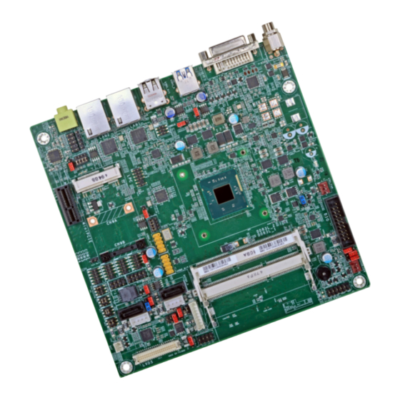
Chapter 2 Chapter 2 - Hardware Installation Important: Board Layout Electrostatic discharge (ESD) can damage your board, processor, disk drives, add-in boards, and other components. Perform installation procedures at an ESD workstation only. If such a station is not available, you can provide some ESD protection by wear- ing an antistatic wrist strap and attaching it to a metal part of the system chassis. -
Page 10: Installing The Dimm Module
Chapter 2 Installing the DIMM Module The system board supports the following memory interface. Single Channel (SC) Note: The system board used in the following illustrations may not resemble the actual Data will be accessed in chunks of 64 bits (8B) from the memory channels. board. -
Page 11: Installing The Heat Sink
Chapter 2 Installing the Heat Sink 5. Grasping the module by its edges, align the module into the socket at an approximately 30 degrees angle. Apply firm even pressure to each end of the module until it slips down into the socket. -
Page 12: Jumper Settings
Chapter 2 Jumper Settings 4. Place the heat sink assembly on top of the CPU. The 4 screws around the heat sink must match the screw holes of the retention module base. We strongly recommend using this type of heat sink assembly because it provides adequate cooling to the components of the Clear CMOS Data system board. -
Page 13: Ps/2 Keyboard/Mouse Power Select
Chapter 2 PS/2 Keyboard/Mouse Power Select USB Power Select 1-2 On: +5V (default) USB 0-1 (JP4) 1-2 On: +5V (default) 2-3 On: +5V_standby 2-3 On: +5V_standby USB 3 USB 4-5 USB 6-7 (JP3) (JP5) (JP10) JP6 is used to select the power of the PS/2 keyboard/mouse port. Selecting +5V_standby will allow you to use the PS/2 keyboard or PS/2 mouse to wake up the system. -
Page 14: Lcd/Inverter Power Select
Chapter 2 LCD/Inverter Power Select Panel Power Select 1-2 On: +12V 1-2 On: +12V (default) 3-4 On: +5V JP21 JP19 2-3 On: +5V 5-6 On: +3.3V (default) JP19 is used to select the power supplied with the LCD panel. JP21 is used to select the power level of LVDS LCD inverter connector. Important: Before powering-on the system, make sure that the power settings of JP19 match the LCD panel’s specification. -
Page 15: Backlight Power Select
Chapter 2 Backlight Power Select Auto Power-on Select 1-2 On: Power-on via power button (default) 1-2 On: +3.3V JP16 (default) JP13 2-3 On: Power-on via AC power 2-3 On: +5V JP13 is used to select the method of powering-on the system. If you want the system to JP16 is used to select the power level of backlight control: +3.3V (default) or +5V. -
Page 16: Com 1 Rs232/422/485 Select
Chapter 2 COM 1 RS232/422/485 Select 1-2 On: RS232 3-4 On: RS422 5-6 On: RS485 (default) Full Duplex COM 1 RS422 RS232 RS485 COM 1: Full Duplex RS232/422/485 Note: When COM 1 RS232/422/485 is selected, JP9 and JP11 must be set in accordance to JP8. -
Page 17: Com 1 Rs232/Power Select
Chapter 2 COM 1 RS232/Power Select SATA DOM Power Select SATA 0 1-2 On: GND (default) JP12 COM 1: RS232/422/485 2-3 On: +5V JP14 JP12 is used to select the power level of SATA DOM. Note: SATA port 0 provides adequate space for SATA DOM. 1-3 (RI), 2-4 (DCD) On: 3-5 (+5V), 4-6 (+12V) On: RS232 (default) -
Page 18: Digital I/O Power Select
Chapter 2 Digital I/O Power Select Digital I/O Output State DIO 3/5/7/9 (JP18) JP17 1-2 On: +5V or DIO 11/13/15/17 +5V_standby (JP20) (default) 1-2 On: +5V_standby (default) 2-3 On: GND 2-3 On: +5V JP17 is used to select the power of Digital I/O signal. Based on the power level of DIO (Digital I/O) selected on JP17, JP18 (DIO pin 3/5/7/9) and JP20 (DIO pin 11/13/15/17) are used to select the output state of Digital I/O: pull high or pull low. -
Page 19: Mini Pcie/Msata Signal Select
Chapter 2 Mini PCIe/mSATA Signal Select Mini PCIe/mSATA Power Select 1-2 On: +3.3V_standby (Mini PCIe) 2-3 On: +3.3V (mSATA) (default) 1-4-7-10, 2-5-8-11 On: 2-5-8-11, 3-6-9-12 On: PCIe (default) mSATA JP1 is used to select the power supplied with the Mini PCIe. JP2 is used to select the Mini PCIe signal. -
Page 20: Sata 1/Msata Signal Select
Chapter 2 SATA 1/mSATA Signal Select Dimming Mode Select 1-4-7-10, 2-5-8-11 On: SATA 1 (default) 1-2 On: PWM Mode (default) JP15 JP22 2-3 On: Voltage Mode 2-5-8-11, 3-6-9-12 On: mSATA JP22 is designed to select the SATA or mSATA signal. JP15 allows you to select the mode for the lightness control of the LVDS panel. -
Page 21: Rear Panel I/O Ports
This jack provides maximum of 100W/120W power and is considered a low power solution. Connect a DC power cord to this jack. Use a power adapter with 12V (for BT101) or 19~24V (for BT103) DC output voltage. Using a voltage higher than the recommended one may fail to boot the system or cause damage to the system board. -
Page 22: Graphics Interface
Chapter 2 Graphics Interface RJ45 LAN Ports The display port consists of the following: • 1 DVI-I port DVI-I LAN 1 LAN 1 LAN 2 LAN 2 Features • Two Intel I210AT PCI Express Gigabit Ethernet controllers ® DVI-I Port The two LAN ports allow the system board to connect to a local area network by means of a network hub. -
Page 23: Usb Ports
2.0 ports (USB 0-1) at the rear panel I/O ports. The 10-pin connectors allow you to connect 4 additional USB 2.0/1.1 ports (USB 4-5/6-7). The additional USB ports may be mounted on a Model Name BT101/BT103 card-edge bracket. Install the card-edge bracket to an available slot at the rear of the system USB 3.0 Native chassis and then insert the USB port cables to a connector. -
Page 24: Audio
Chapter 2 Audio I/O Connectors SATA (Serial ATA) Connectors SATA 2.0 3Gb/s SATA 0 Line-out Front Audio SATA 1 Features • 2 Serial ATA 2.0 ports with data transfer rate up to 3Gb/s (SATA 0 and SATA 1) • Integrated Advanced Host Controller Interface (AHCI) controller Rear Audio The Serial ATA connectors are used to connect Serial ATA devices. -
Page 25: Sata (Serial Ata) Power Connectors
Chapter 2 SATA (Serial ATA) Power Connectors Digital I/O and/or Power Connector Digital I/O SATA Power 0 +12V Ground Ground SATA Power 1 The 8-bit Digital I/O connector provides powering-on function to external devices that are connected to these connectors. The pin functions of the 8-bit digital I/O connector are listed The SATA power connectors supply power to the SATA drive. -
Page 26: Cooling Fan Connectors
Chapter 2 Cooling Fan Connectors Front Panel Connector Front RESET-SW PWR-BTN Panel HDD-LED PWR-LED CPU Fan System Fan HDD-LED - HDD LED This LED will light when the hard drive is being accessed. RESET-SW - Reset Switch This switch allows you to reboot without having to power off the system. PWR-BTN - Power Switch This switch is used to power on or off the system. -
Page 27: Com (Serial) Ports
Chapter 2 COM (Serial) Ports Important: When COM 1 RS232/422/485 is selected, JP9 and JP11 must be set in accordance to JP8. COM 2 COM 3 COM 4 COM 2/COM 3/COM 4: RS232 COM 1: RS232/422/485 COM 2 to COM 4 are fixed at RS232. The pin functions of COM port 1 will vary according to JP8’s, JP9’s and JP11’s setting. -
Page 28: Lvds Lcd Panel Connector
Panel Power Refer to the “Jumper Settings” section in this chapter for settings relevant to Panel Power Panel Power the LCD panel. Note: DFI board's LVDS connector: Hirose DF13-40DP-1.25V(91)/40P/1.25mm; cable side connector: Hirose DF13-40DS-1.25C. Chapter 2 Hardware Installation www.dfi .com... -
Page 29: Ps/2 Keyboard/Mouse Connector
Chapter 2 PS/2 Keyboard/Mouse Connector Wake-On-PS/2 Keyboard/Mouse The Wake-On-PS/2 Keyboard/Mouse function allows you to use the PS/2 keyboard or PS/2 mouse to power-on the system. To use this function: • Jumper Setting JP6 must be set to “2-3 On: 5V_standby”. Refer to “PS/2 Keyboard/Mouse Power Select” in this chapter for more information. -
Page 30: Smbus Connector
Chapter 2 SMBus Connector Expansion Slots SMBUS Data SMBus +3.3V_standby SMBUS_Alert SMBUS Clock Mini PCI Express PCI Express x1 PCI Express x1 Slot The SMBus (System Management Bus) connector is used to connect SMBus devices. It is a multiple device bus that allows multiple chips to connect to the same bus and enable each one Install PCI Express cards such as network cards or other cards that comply to the PCI Express to act as a master by initiating data transfer. -
Page 31: S/Pdif Connector
Chapter 2 S/PDIF Connector LAN LED Connector LAN 2 State LAN 2 State LAN 1 State S/PDIF LAN 1 State The S/PDIF connector is used to connect an external S/PDIF port. Your S/PDIF port may be The LAN LED connector is used to detect the connection state of RJ45 LAN ports when the mounted on a card-edge bracket. -
Page 32: Chassis Intrusion Connector
Chapter 2 Chassis Intrusion Connector LPC Connector Chassis Ground Intrusion Signal The board supports the chassis intrusion detection function. Connect the chassis intrusion sensor cable from the chassis to this connector. When the system’s power is on and a chassis intrusion occurred, an alarm will sound. -
Page 33: Standby Power Led
Chapter 2 Standby Power LED Battery Standby Power LED +3.3V Battery This LED will lit red when the system is in the standby mode. It indicates that there is power on the system board. Power-off the PC and then unplug the power cord prior to installing any Connect to the devices. -
Page 34: Chapter 3 - Bios Setup
Chapter 3 Chapter 3 - BIOS Setup Legends Overview Keys Function The BIOS is a program that takes care of the basic level of communication between the CPU and peripherals. It contains codes for various advanced features found in this system board. Right and Left arrows Moves the highlight left or right to select a menu. -
Page 35: Ami Bios Setup Utility
Chapter 3 AMI BIOS Setup Utility Advanced The Advanced menu allows you to configure your system for basic operation. Some entries are Main defaults required by the system board, while others, if enabled, will improve the performance of your system or let you set some features according to your preference. The Main menu is the first screen that you will see when you enter the BIOS Setup Utility. - Page 36 Chapter 3 Super IO Configuration Serial Port 1 Configuration to Serial Port 4 Configuration This section is used to configure the parameters of the super IO chip. Sets the parameters of serial port 1 (COM A) and serial port 4 (COM D). Aptio Setup Utility - Copyright (C) 2013 American Megatrends, Inc.
- Page 37 Chapter 3 Serial Port Aptio Setup Utility - Copyright (C) 2013 American Megatrends, Inc. Enable or disable the serial COM port. Advanced Change Settings Serial Port 3 Confi guration Enable or Disable Serial Port (COM) Serial Port [Enabled] Select the IO/IRQ settings for the super I/O device. Device Settings IO=3E8h;...
- Page 38 Chapter 3 System Smart Fan Control PC Health Status When this feature is set to Automatic, the System’s fan speed will rotate according to This section is used to monitor the hardware status. the System’s temperature. The higher the temperature, the faster the speed of rotation. Aptio Setup Utility - Copyright (C) 2013 American Megatrends, Inc.
- Page 39 Chapter 3 CPU Configuration SATA Configuration This section is used to configure the CPU. It will also display the detected CPU information. This section is used to enable or disable SATA devices. Aptio Setup Utility - Copyright (C) 2013 American Megatrends, Inc. Aptio Setup Utility - Copyright (C) 2013 American Megatrends, Inc.
- Page 40 Chapter 3 Network Stack Configuration Ipv4 PXE Support This section is used to enable or disable network stack settings. When enabled, Ipv4 PXE boot supports. When disabled, Ipv4 PXE boot option will not be created. Aptio Setup Utility - Copyright (C) 2013 American Megatrends, Inc. Ipv6 PXE Support Advanced Network Stack...
- Page 41 Chapter 3 CSM Configuration Trusted Computing This section configures the CSM settings. This section configures settings relevant to Trusted Computing innovations. Aptio Setup Utility - Copyright (C) 2013 American Megatrends, Inc. Aptio Setup Utility - Copyright (C) 2013 American Megatrends, Inc. Advanced Advanced Enables or Disables...
- Page 42 USB type in table 2 below. Optimized Defaults Save & Reset ESC: Exit Table 2. The Type of USB Ports Version 2.16.1242 Copyright (C) 2013 American Megatrends, Inc. Model Name BT101/BT103 Legacy USB Support USB 3.0 Native Enabled USB 0 Native Enable legacy USB.
- Page 43 Chapter 3 Security Configuration Intel(R) I210 Gigabit Network Connection - 00:01:29:5D... This section only displays the setting relevant to the Intel(R) Anti-Theft Technology. This section is used to configure the parameters of Gigabit Ethernet device. Aptio Setup Utility - Copyright (C) 2013 American Megatrends, Inc. Aptio Setup Utility - Copyright (C) 2013 American Megatrends, Inc.
- Page 44 Chapter 3 NIC Configuration Intel(R) I210 Gigabit Network Connection - 00:01:29:5D... This field is used to configure the network device. This section is used to configure the parameters of Gigabit Ethernet device. Aptio Setup Utility - Copyright (C) 2013 American Megatrends, Inc. Aptio Setup Utility - Copyright (C) 2013 American Megatrends, Inc.
-
Page 45: Chipset
Chapter 3 Chipset NIC Configuration This field is used to configure the network device. This section configures relevant chipset functions. Aptio Setup Utility - Copyright (C) 2013 American Megatrends, Inc. Aptio Setup Utility - Copyright (C) 2013 American Megatrends, Inc. Advanced Main Advanced... - Page 46 Chapter 3 North Bridge Intel IGD Configuration This section configures the North bridge parameters. Aptio Setup Utility - Copyright (C) 2013 American Megatrends, Inc. Chipset Aptio Setup Utility - Copyright (C) 2013 American Megatrends, Inc. GOP Information Chipset Intel(R) GOP Driver [N/A] ...
- Page 47 Chapter 3 LCD Control LCD Panel Type Select the LCD panel used by Internal Graphics Device by selecting the appropriate Aptio Setup Utility - Copyright (C) 2013 American Megatrends, Inc. setup item. Please refer to the screen shown below. Chipset LCD Control Select the Video Device Aptio Setup Utility - Copyright (C) 2013 American Megatrends, Inc.
- Page 48 Chapter 3 South Bridge Memory Configuration This field is used to configure the parameters of the South Bridge. This section only displays the parameter of memory configuration. Aptio Setup Utility - Copyright (C) 2013 American Megatrends, Inc. Aptio Setup Utility - Copyright (C) 2013 American Megatrends, Inc. Chipset Chipset Memory Information...
- Page 49 Chapter 3 Azalia HD Audio PCI Express Configuration This section configues Azalia HD Audio options. This section configues settings relevant to PCI Express devices. Aptio Setup Utility - Copyright (C) 2013 American Megatrends, Inc. Aptio Setup Utility - Copyright (C) 2013 American Megatrends, Inc. Chipset Chipset Control Detection of the...
-
Page 50: Security
Chapter 3 Security Boot Aptio Setup Utility - Copyright (C) 2013 American Megatrends, Inc. Aptio Setup Utility - Copyright (C) 2013 American Megatrends, Inc. Main Advanced Main Advanced Chipset Security Boot Save & Exit Chipset Security Boot Save & Exit Number of seconds to Password Description Set Administrator... -
Page 51: Save & Exit
Chapter 3 Save & Exit Updating the BIOS To update the BIOS, you will need the new BIOS file and a flash utility, AFUDOS. EXE. Please contact technical support or your sales representative for the files. Aptio Setup Utility - Copyright (C) 2013 American Megatrends, Inc. Main Advanced Chipset... -
Page 52: Notice: Bios Spi Rom
Chapter 3 Notice: BIOS SPI ROM 1. The Intel Management Engine has already been integrated into this system board. Due to ® the safety concerns, the BIOS (SPI ROM) chip cannot be removed from this system board and used on another system board of the same model. 2. -
Page 53: Chapter 4 - Supported Software
Install drivers, utilities and software applications that are required to facilitate and enhance the performance of the system board. You may acquire the software from your sales representa- tives, from an optional DVD included in the shipment, or from the website download page at https://www.dfi.com/DownloadCenter. For Windows 8.x Note: This step can be ignored if the applications are standalone files. - Page 54 Chapter 4 Intel Chipset Software Installation Utility 3. Go through the readme docu- ment for more installation tips then click Next. The Intel Chipset Device Software is used for updating Windows INF files so that the Intel ® chipset can be recognized and configured properly in the system. To install the utility, click “Intel Chipset Software Installation Utility”...
- Page 55 Chapter 4 Intel HD Graphics Drivers 3. Go through the readme docu- ment for system requirements and installation tips then click To install the driver, click “Intel HD Graphics Drivers” on the main menu. Next. 1. Setup is now ready to install the graphics driver.
- Page 56 Chapter 4 Intel LAN Drivers 4. Click Install to begin the installation. To install the driver, click “Intel LAN Drivers” on the main menu. 1. Setup is ready to install the driver. Click Next. 5. After completing installa- tion, click Finish. 2.
- Page 57 Chapter 4 Kernel Mode Driver Framework (For Windows 7 only) Intel Trusted Execution Engine Driver To install the driver, click “Kernel Mode Driver Framework” on the main menu. To install the driver, click “Intel Trusted Execution Engine Driver” on the main menu. 1.
- Page 58 Chapter 4 Realtek Audio Drivers 3. The step displays the installing status in the progress. To install the driver, click “Realtek Audio Drivers” on the main menu 1. Setup is now ready to install the audio driver. Click Next. 2. Follow the remainder of the steps on the screen;...
- Page 59 Chapter 4 Intel Sideband Fabric Device (MBI) Driver 3. The step performs setup operations. Click “Next“ to continue. (For Windows 8 only) To install the driver, click “Intel Sideband Fabric Device (MBI) Driver” on the main menu. 1. The setup program will be installed.
- Page 60 Chapter 4 HW Utility 3. Enter “User Name” and “Organi- zation” information and then click Next HW Utility provides information about the board, HW Health, Watchdog, DIO, and Backlight. To access the utility, click “HW Utility” on the main menu. Note: If you are using Windows 7, you need to access the operating system as an administrator to be able to install the utility.
- Page 61 Chapter 4 The HW Utility icon will appear on the desktop. Double-click the icon to open the utility. Information HW Health Set WatchDog HW Health Chapter 4 Supported Software www.dfi .com...
- Page 62 Chapter 4 Infineon TPM Driver and Tool (option) To install the driver, click “Infineon TPM driver and tool (option)” on the main menu. 1. The setup program is preparing to install the driver. 2. The setup program is now ready to install the utility.
- Page 63 Chapter 4 4. Enter the necessary information 7. TPM requires installing the Micro- and then click Next. soft Visual C++ package prior to installing the utility. Click Install. 5. Select a setup type and then click 8. The setup program is currently Next.
- Page 64 Chapter 4 Intel USB 3.0 Drivers (For Windows 7 Only) 10. Click “Yes“ to restart your system. To install the driver, click “Intel USB 3.0 Driver” on the main menu. 1. Setup is ready to install the driver. Click Next. 2.
- Page 65 Chapter 4 Adobe Acrobat Reader 9.3 3. Go through the readme docu- ment for more installation tips then click Next. To install the reader, click “Adobe Acrobat Reader 9.3” on the main menu. 1. Click Next to install or click Change Destination Folder to select another folder.
-
Page 66: Chapter 5 - Digital I/O Programming Guide
Chapter 5 Chapter 5 - Digital I/O Programming Guide The Configuration Register (register 3) configures the direction of the I/O pins. If a bit in this register is set to 1, the corresponding port pin is enabled as an input with a high-impedence Register Description output driver. - Page 67 Chapter 5 Function Description GPIO Output Process I2CWriteByte(SlaveAddr, SubAddr, Data): #defi ne SLAVE_ADDR 0x42 Write a Byte data to a specified I2C Device. #defi ne INPUT_PORT 0x00 #defi ne OUTPUT_PORT 0x01 I2CReadByte(SlaveAddr, SubAddr, *Data): 0x02 #defi ne INVERSION_PORT Read a Byte data from a specified I2C Device. 0x03 #defi...
-
Page 68: Appendix A - Watchdog Sample Code
Appendix A Appendix A - Watchdog Sample Code ;Software programming example: ;--------------------------------------------- ;(1) Enter Super IO Confi guration mode ;--------------------------------------------- DX,4EH AL,87H DX,AL DX,AL ;------------------------------------------------------------------------------------------- ;(2) Confi guration Logical Device 8, register CRF0/CRF1 (WDT Control/WDT timer) ;------------------------------------------------------------------------------------------- DX,4EH AL,07H ;Ready to Program Logical Device DX,AL DX,4FH AL,08H... -
Page 69: Appendix B - System Error Message
Appendix B Appendix B - System Error Message Standard Status Codes When the BIOS encounters an error that requires the user to correct something, either a beep PEI Status Codes code will sound or a message will be displayed in a box in the middle of the screen and the message, PRESS F1 TO CONTINUE, CTRL-ALT-ESC or DEL TO ENTER SETUP, will be shown in the information box at the bottom. - Page 70 Appendix B DXE Phase Codes ACPI Checkponts Beep Code DXE Error Codes Appendix B System Error Message www.dfi .com...
-
Page 71: Appendix C - Troubleshooting
Appendix C Appendix C - Troubleshooting Checklist The picture seems to be constantly moving. Troubleshooting Checklist 1. The monitor has lost its vertical sync. Adjust the monitor’s vertical sync. 2. Move away any objects, such as another monitor or fan, that may be creating a magnetic This chapter of the manual is designed to help you with problems that you may encounter field around the display. - Page 72 Appendix C Hard Drive System Board 1. Make sure the add-in card is seated securely in the expansion slot. If the add-in card is Hard disk failure. loose, power off the system, re-install the card and power up the system. 1.
Need help?
Do you have a question about the BT101 and is the answer not in the manual?
Questions and answers