Sign In
Upload
Download
Table of Contents
Contents
Add to my manuals
Delete from my manuals
Share
URL of this page:
HTML Link:
Bookmark this page
Add
Manual will be automatically added to "My Manuals"
Print this page
×
Bookmark added
×
Added to my manuals
Manuals
Brands
DFI Manuals
Motherboard
BT551
User manual
DFI BT551 User Manual
Embedded sbc 3.5”
Hide thumbs
1
2
Table Of Contents
3
4
5
6
7
8
9
10
11
12
13
14
15
16
17
18
19
20
21
22
23
24
25
26
27
28
29
30
31
32
33
34
35
36
37
38
39
40
41
42
43
44
45
46
47
48
49
50
51
52
53
54
55
56
57
58
59
60
61
62
63
64
page
of
64
Go
/
64
Contents
Table of Contents
Troubleshooting
Bookmarks
Table of Contents
Copyright
FCC and DOC Statement on Class B
Trademarks
Table of Contents
About this Manual
Safety Measures
Static Electricity Precautions
Warranty
About the Package
Chapter 1 - Introduction
Specifications
Features
Chapter 2 - Hardware Installation
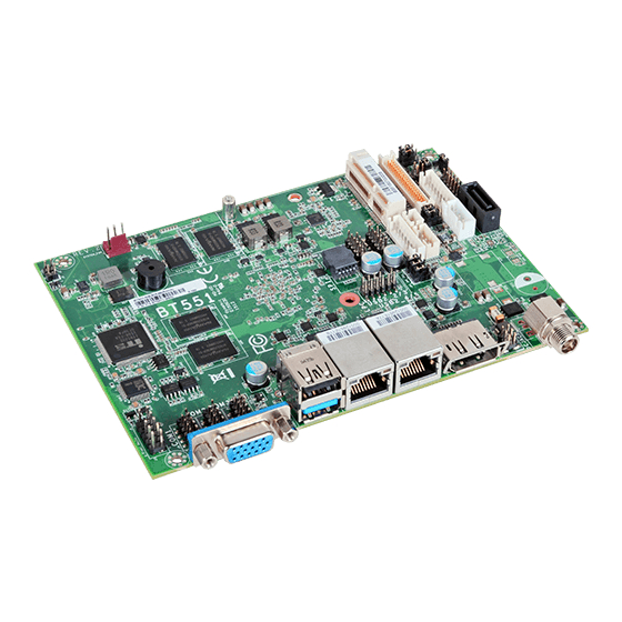
Board Layout
Block Diagram
Mechanical Diagram
System Memory
Jumper Settings
Clear CMOS Data
Auto Power-On Select
Backlight Power Select
Panel Power Select
Lcd/Inverter Power Select
Dimming Mode Select
Digital I/O Power Select
Digital I/O Output State
Rear Panel I/O Ports
DC-In (BT551)/15~36V DC-In (BT553)
Graphics Interfaces
RJ45 LAN Ports
USB Ports
I/O Connectors
Digital I/O Connector
Digital I/O Power Connector
Front Audio Connector
COM (Serial) Ports
Front Panel Connector
SATA (Serial ATA) Connector
SATA (Serial ATA) Power Connector
LVDS LCD Panel Connector
Lcd/Inverter Power Connector
Expansion Slot
Cooling Fan Connector
Smbus Connector
Chassis Intrusion Connector
LPC Connector
Standby Power LED
Battery
Chapter 3 - BIOS Setup
Overview
Insyde BIOS Setup Utility
Main
Advanced
Security
Power
Boot
Exit
Notice: BIOS SPI ROM
Chapter 4 - Supported Software
Intel Chipset Software Installation Utility
Intel Lan Drivers
Realtek Audio Drivers
Chapter 5 - Digital I/O Programming Guide
Sample Code
Gpio Configuration
Chapter 6 - Install Windows 7 32-Bit into Emmc Storage Devices
Chapter 7 - Install Windows 7 64-Bit into SD and Emmc Storage Devices
Appendix A - Watchdog Sample Code
Appendix B - System Error Message
Appendix C - Troubleshooting
Hard Drive
System Board
Serial Port
Advertisement
Quick Links
1
Chapter 3 - Bios Setup
2
Advanced
3
Insyde Bios Setup Utility
4
Power
5
Chapter 7 - Install Windows 7 64-Bit into Sd and Emmc Storage Devices
Download this manual
BT551/BT553
Embedded SBC 3.5"
User's Manual
A35300517
1
Table of
Contents
Previous
Page
Next
Page
1
2
3
4
5
Advertisement
Table of Contents
Need help?
Do you have a question about the BT551 and is the answer not in the manual?
Ask a question
Questions and answers
Related Manuals for DFI BT551
Motherboard DFI BT700 User Manual
Qseven board (52 pages)
Motherboard DFI BT553 User Manual
Embedded sbc 3.5” (64 pages)
Motherboard DFI BT253 User Manual
Embedded sbc 4” (62 pages)
Motherboard DFI BT160 User Manual
Industrial motherboard (71 pages)
Motherboard DFI BT100 Quick Reference
(4 pages)
Motherboard DFI BT101 User Manual
Mini-itx industrial motherboard (72 pages)
Motherboard DFI BL631-D User Manual
System board (122 pages)
Motherboard DFI BL100 Series User Manual
Bl100 series system board (127 pages)
Motherboard DFI BL600-DR User Manual
System board (149 pages)
Motherboard DFI BL330-BR User Manual
(123 pages)
Motherboard DFI BE170 User Manual
Mini-itx industrial motherboard (61 pages)
Motherboard DFI BL630-DR User Manual
(138 pages)
Motherboard DFI BW051 User Manual
Embedded sbc 2.5" (45 pages)
Motherboard DFI Blood-Iron LanParty Bi 785G-M35 User Manual
System board (152 pages)
Motherboard DFI LanParty BI 785G-M35 User Manual
(176 pages)
Motherboard DFI BW551 User Manual
Embedded sbc 3.5” (50 pages)
This manual is also suitable for:
Bt553
Table of Contents
Print
Rename the bookmark
Delete bookmark?
Delete from my manuals?
Login
Sign In
OR
Sign in with Facebook
Sign in with Google
Upload manual
Upload from disk
Upload from URL


Need help?
Do you have a question about the BT551 and is the answer not in the manual?
Questions and answers