Table of Contents
Advertisement
Advertisement
Table of Contents

Related Manuals for DFI BL600-DR


Summary of Contents for DFI BL600-DR
- Page 1 BL600-DR BL600-D System Board User’s Manual A04560218...
- Page 2 Copyright This publication contains information that is protected by copyright. No part of it may be reproduced in any form or by any means or used to make any transformation/adaptation without the prior writ- ten permission from the copyright holders. This publication is provided for informational purposes only.
-
Page 3: Fcc And Doc Statement On Class B
FCC and DOC Statement on Class B This equipment has been tested and found to comply with the limits for a Class B digital device, pursuant to Part 15 of the FCC rules. These limits are designed to provide reasonable protection against harmful interference when the equipment is operated in a residential installation. -
Page 4: Table Of Contents
Table of Contents About this Manual................Warranty....................Static Electricity Precaution..............Safety Measures..................About the Package................Before Using the System Board............Chapter 1 - Introduction..............Specifications........................... Features.............................. Chapter 2 - Hardware Installation............ System Board Layout ......................System Memory.......................... CPU............................... Jumper Settings..........................Rear Panel I/O Ports...................... -
Page 5: About This Manual
About this Manual An electronic file of this manual is included in the CD. To view the user’s manual in the CD, insert the CD into a CD-ROM drive. The autorun screen (Main Board Utility CD) will appear. Click “User’s Manual”... -
Page 6: Static Electricity Precaution
Introduction Static Electricity Precautions It is quite easy to inadvertently damage your PC, system board, components or devices even before installing them in your system unit. Static electrical discharge can damage computer components without causing any signs of physical damage. You must take extra care in handling them to ensure against electrostatic build-up. -
Page 7: About The Package
Introduction About the Package The system board package contains the following items. If any of these items are missing or damaged, please contact your dealer or sales representative for assistance. The system board A user’s manual One IDE cable Two USB port cables Two Serial ATA data cables Two Serial ATA power cables One “Main Board Utility”... -
Page 8: Chapter 1 - Introduction
• Intel chipset ® - Intel Q35 Express chipset ® - Intel ICH9R I/O Controller Hub (BL600-DR) ® Intel ICH9 I/O Controller Hub (BL600-D) ® System Memory • Four 240-pin DDR2 DIMM sockets • Supports dual channel (128-bit wide) memory interface •... - Page 9 • IEEE 802.3 (10/100Mbps) and IEEE 802.3ab (1Gbps) compliant Serial ATA • Supports Serial ATA interfaces which are compliant with SATA 1.0 specification • BL600-DR - Supports up to 6 SATA devices - SATA speed up to 3Gb/s - RAID 0, RAID 1, RAID 0+1 and RAID 5 •...
- Page 10 • 1 front audio connector for line-out and mic-in jacks • 1 CD-in internal audio connector • 1 S/PDIF-in/out connector • 1 connector for IrDA interface • 6 Serial ATA connectors (BL600-DR) 4 Serial ATA connectors (BL600-D) • 1 40-pin IDE connector • 1 floppy connector •...
-
Page 11: Features
Introduction Features The Watchdog Timer function allows your watchdog timer application to regularly “clear” the system at the set time interval. If the system hangs or fails to function, it will reset at the set time interval so that your system will continue to operate. - Page 12 SATA 1.0 specification. With speed of up to 3Gbps, it improves hard drive performance faster than the standard parallel ATA whose data transfer rate is 100MB/s. The BL600-DR board allows configuring RAID 0, RAID 1, RAID 0+1 and RAID 5 on Serial ATA drives connected to SATA ports 0, 1, 2, 3, 4 and 5.
- Page 13 Introduction This feature allows the system that is in the wake-on-ring Suspend mode or Soft Power Off mode to wake-up/power-on to respond to calls coming from an external mo- dem or respond to calls from a modem PCI card that uses the PCI PME (Power Management Event) signal to remotely wake up the Important: The 5V_standby power source of your power supply must sup-...
- Page 14 Introduction The RTC installed on the system board allows your rtc timer system to automatically power-on on the set date and time. The system board is designed to meet the ACPI ACPI STR (Advanced Configuration and Power Interface) speci- fication. ACPI has energy saving features that enables PCs to imple- ment Power Management and Plug-and-Play with operating systems that support OS Direct Power Management.
-
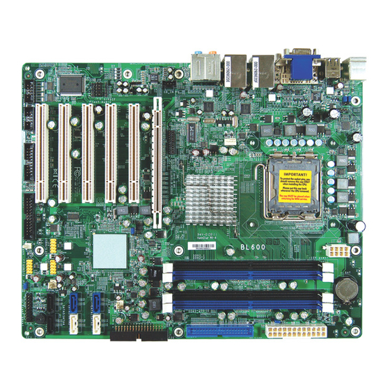
Page 15: Chapter 2 - Hardware Installation
Chassis open Front panel COM 2 COM 1 The BL600-DR board (shown above) uses the ICH9R southbridge and supports 6 SATA ports. On a BL600-D board, it uses ICH9 southbridge and supports 4 SATA ports only (SATA 0/1/4/5). Note: The DVI-I port supports DVI-D signal only. -
Page 16: System Memory
Hardware Installation Warning: Electrostatic discharge (ESD) can damage your system board, proces- sor, disk drives, add-in boards, and other components. Perform the upgrade instruction procedures described at an ESD workstation only. If such a station is not available, you can provide some ESD protec- tion by wearing an antistatic wrist strap and attaching it to a metal part of the system chassis. -
Page 17: Hardware Installation
Hardware Installation The system board supports the following memory interface. Single Channel (SC) Data will be accessed in chunks of 64 bits (8B) from the memory channels. Dual Channel (DC) Data will be accessed in chunks of 128 bits from the memory chan- nels. -
Page 18: Installing The Dim Module
Hardware Installation Installing the DIM Module Note: The system board used in the following illustrations may not resemble the actual board. These illustrations are for reference only. 1. Make sure the PC and all other peripheral devices connected to it has been powered down. 2. - Page 19 Hardware Installation 6. Grasping the module by its edges, position the module above the socket with the “notch” in the module aligned with the “key” on the socket. The keying mechanism ensures the module can be plugged into the socket in only one way. 7.
-
Page 20: Cpu
Hardware Installation Overview The system board is equipped with a surface mount LGA 775 socket. This socket is exclusively designed for installing a LGA 775 packaged Intel CPU. Important: 1. Before you proceed, make sure (1) the LGA775 socket 1. Before you proceed, make sure (1) the LGA775 socket 1. - Page 21 Hardware Installation Cover 4. The CPU socket comes with a cover that is attached with a remov- able protective cap. The Protective cap cap is used to protect the CPU socket against dust and harmful parti- Lever cles. Remove the protec- tive cap only when you are about to install the CPU.
- Page 22 Hardware Installation 8. Position the CPU above the socket. The gold mark on the CPU must align with pin 1 of the CPU socket. Important: Handle the CPU by its edges and avoid touch- ing the pins. Pin 1 of the socket Gold mark 9.
- Page 23 Hardware Installation 10. Once the CPU is in Cover place, move the cover down. 11. Push the lever down to lock the socket. The lever should hook onto the side tab to indicate that the CPU is com- pletely secured in the Lever socket.
- Page 24 Hardware Installation 2. Place the heat sink on Mounting hole top of the CPU. The 4 studs around the heat sink which are used to Mounting hole secure the heat sink onto the system board must match the 4 mounting holes around the socket.
-
Page 25: Jumper Settings
Hardware Installation Jumper Settings Clear CMOS Data 1-2 On: Normal 2-3 On: (default) Clear CMOS Data If you encounter the following, a) CMOS data becomes corrupted. b) You forgot the supervisor or user password. you can reconfigure the system with the default values stored in the ROM BIOS. - Page 26 Hardware Installation PS/2 Power Select 2-3 On: 1-2 On: 5V (default) 5V_standby JP1 is used to select the power of the PS/2 keyboard/mouse port. Selecting 5V_standby will allow you to use the PS/2 keyboard or PS/2 mouse to wake up the system. BIOS Setting Configure the PS/2 keyboard/mouse wake up function in the Inte- grated Peripherals submenu (“Super IO Device”...
-
Page 27: Usb Power Select
Hardware Installation USB Power Select USB 6/7/8/9/10/11 (JP3) 2-3 On: 1-2 On: 5V (default) 5V_standby USB 0/1/2/3/4/5 (JP2) 1-2 On: 5V 2-3 On: (default) 5V_standby JP2 and JP3 are used to select the power of the USB ports. Select- ing 5V_standby will allow you to use the USB keyboard or USB mouse to wake up the system. - Page 28 Hardware Installation PCIE x16 / DVI Select 1-10, 11-20 On: DVI (default) 11-20, 21-30 On: PCIE x16 The system board allows connecting a device to either the DVI port at the rear panel or to the PCI Express x16 card. However, you cannot use devices connected to both the DVI port and PCI Ex- press x16 card at the same time.
- Page 29 Hardware Installation Power-on Select 2-3 On: 1-2 On: Power-on via Power-on via AC power power button (default) JP6 is used to select the method of powering on the system. If you want the system to power-on whenever AC power comes in, set JP6 pins 2 and 3 to On.
-
Page 30: Rear Panel I/O Ports
Hardware Installation Rear Panel I/O Ports Center/ Subwoofer Rear R/L PS/2 LAN 1 LAN 2 Mouse Line-in USB 11 Line-out Mic-in PS/2 K/B USB 10 DVI-I USB 8/9 USB 6/7 Side R/L The rear panel I/O ports consist of the following: •... - Page 31 Hardware Installation PS/2 Mouse and PS/2 Keyboard Ports PS/2 Mouse PS/2 Keyboard These ports are used to connect a PS/2 mouse and a PS/2 key- board. The PS/2 mouse por t uses IRQ12. If a mouse is not connected to this port, the system will reserve IRQ12 for other expansion cards.
- Page 32 Hardware Installation • BIOS Setting: Configure the PS/2 wake up function in the Integrated Peripherals submenu (“Super IO Device” section) of the BIOS. Refer to chapter 3 for more information. Important: The 5V_standby power source of your power supply must sup- port ≥...
-
Page 33: Universal Serial Bus Connectors
Hardware Installation Universal Serial Bus Connectors USB 11 USB 10 USB 9 USB 8 USB 2-1 USB 7 USB 8-7 USB 6 USB 5-4 The system board supports 12 USB 2.0/1.1 ports. USB allows data exchange between your computer and a wide range of simultane- ously accessible external Plug and Play peripherals. - Page 34 Hardware Installation Driver Installation You may need to install the proper drivers in your operating system to use the USB device. Refer to your operating system’s manual or documentation for more information. Refer to chapter 4 for more information about installing the USB 2.0 drivers.
-
Page 35: Vga Port
Hardware Installation VGA Port The VGA port is used for connecting a VGA monitor. Connect the monitor’s 15-pin D-shell cable connector to the VGA port (Blue). After you plug the monitor’s cable connector into the VGA port, gently tighten the cable screws to hold the connector in place. BIOS Setting Configure the onboard VGA in the Advanced Chipset Features submenu of the BIOS. - Page 36 Hardware Installation DVI-I Port DVI-I The DVI-I port is used to connect a digital LCD monitor or LCD TV. This port supports DVI-D signal only. Connect the display device’s cable connector to the DVI port on the board. After you plug the cable connector into the DVI port, gently tighten the cable screws to hold the connector in place.
- Page 37 Hardware Installation RJ45 Fast-Ethernet Port LAN 1 LAN 2 The two onboard RJ45 LAN ports allow the system board to con- nect to a local area network by means of a network hub. BIOS Setting Configure the onboard LAN in the Advanced Chipset Features submenu (“PCI Express Root Port Func”...
- Page 38 Hardware Installation Audio Rear audio Center/ Line-in Subwoofer Line-out Rear R/L Mic-in Side R/L Front audio Rear Panel Audio (CN5) Center/Subwoofer Jack (Orange) This jack is used to connect to the center and subwoofer speak- ers of the audio system. Rear Right/Left Jack (Black) This jack is used to connect to the rear right and rear left speak- ers of the audio system.
- Page 39 Hardware Installation Line-out - Front Right/Left Jack (Lime) This jack is used to connect to the front right and front left speakers of the audio system. Mic-in Jack (Pink) This jack is used to connect an external microphone. Front Audio The front audio connector (J26) allows you to connect to the line- out and mic-in jacks that are at the front panel of your system.
-
Page 40: I/O Connectors
Hardware Installation I/O Connectors CD-in Internal Audio Connector Right audio channel Ground Ground Left audio channel The CD-in connector is used to receive audio from a CD-ROM drive, TV tuner or MPEG card. - Page 41 Hardware Installation S/PDIF Connector SPDIF out SPDIF in The S/PDIF connector is used to connect external S/PDIF ports. Your S/PDIF ports may be mounted on a card-edge bracket. Install the card-edge bracket to an available slot at the rear of the system chassis then connect the audio cable connector to this connector.
-
Page 42: Dio Connector
Hardware Installation DIO Connector The DIO (Digital I/O) connector provides powering-on function to an external device that is connected to this connector. Digital I/O Connector Function Pins Function Pins +12V DIO7 +12V DIO6 DIO5 DIO4 DIO3 DIO2 5VSB DIO1 5VSB DIO0... -
Page 43: Parallel Port
Hardware Installation Parallel Port The 25-pin connector is for connecting an external parallel port. The parallel por t connects your PC to a parallel printer. It supports SPP, ECP and EPP. Setting Function Allows normal speed operation but (Standard Parallel Port) in one direction only. - Page 44 Hardware Installation Connecting the Parallel Port Cable Your parallel port may be mounted on a card-edge bracket. Install the card-edge bracket to an available slot at the rear of the system chassis then insert the cable to this connector. Make sure the colored stripe on the ribbon cable is aligned with pin 1 of this connector.
-
Page 45: Floppy Disk Drive Connector
Hardware Installation Floppy Disk Drive Connector The 90 floppy disk drive connector supports a standard floppy disk drive. The floppy cable can be inserted into this connector only if pin 1 of the cable is aligned with pin 1 of this connector. Connecting the Floppy Disk Drive Cable Install one end of the floppy disk drive cable into the floppy connector on the system board and the other end-most connector... -
Page 46: Serial Ata Connectors
SATA 1 (J18) SATA 2 (J19) SATA 3 (J20) SATA 4 (J21) SATA 5 (J22) • BL600-DR Supports up to 6 SATA devices (SATA 0/1/2/3/4/5) SATA speed up to 3Gb/s RAID 0, RAID 1, RAID 0+1 and RAID 5 • BL600-D... -
Page 47: Ide Disk Drive Connectors
Hardware Installation IDE Disk Drive Connectors The PCI IDE connector will interface two Enhanced IDE (Integrated Drive Electronics) disk drives. The IDE cable can be inserted into this connector only if pin 1 of the cable is aligned with pin 1 of the connector. - Page 48 Hardware Installation Adding a Second IDE Disk Drive When using two IDE drives, one must be set as the master and the other as the slave. Follow the instructions provided by the drive manufacturer for setting the jumpers and/or switches on the drives. The system board suppor ts Enhanced IDE or ATA-2, ATA/33, ATA/66 and ATA/100 hard drives.
- Page 49 Hardware Installation Serial (COM) Port COM 2 COM 1 The two 9-pin connectors are for connecting external serial ports. The serial port cable is an optional item and must be purchased separately. Insert the connector that is attached to the serial port cable to COM 1 or COM 2 then install the serial port bracket to an available bracket slot at the rear of the system chassis.
-
Page 50: Irda Connector
Hardware Installation IrDA Connector IRRX N. C. Ground IRTX Connect the cable connector from your IrDA module to the IrDA connector on the system board. Note: The sequence of the pin functions on some IrDA cable may be reversed from the pin function defined on the system board. Make sure to connect the cable to the IrDA connector accord- ing to their pin functions. -
Page 51: Cooling Fan Connectors
Hardware Installation Cooling Fan Connectors Ground Power Sense Speed Power Control Ground Sense CPU fan 2nd fan Power Ground Sense System fan Connect the CPU fan’s cable connector to the CPU fan connector on the system board. The 2nd fan and system fan connectors are used to connect additional cooling fans. - Page 52 Hardware Installation Chassis Open Connector Chassis signal Ground The system board supports the chassis intrusion detection function. Connect the chassis intrusion sensor cable from the chassis to the chassis open connector. Whenever a chassis component has been removed, the sensor sends signal to the connector alerting you of a chassis intrusion event.
-
Page 53: Power Connectors
Hardware Installation Power Connectors Use a power supply that complies with the ATX12V Power Supply Design Guide Version 1.1. An ATX12V power supply unit has a standard 24-pin ATX main power connector that must be inserted onto CN9. 1 2 2 4 +3.3VDC +12VDC +5VDC... - Page 54 Hardware Installation The system board requires a minimum of 300 Watt power supply to operate. Your system configuration (CPU power, amount of memory, add-in cards, peripherals, etc.) may exceed the minimum power requirement. To ensure that adequate power is provided, we strongly recommend that you use a minimum of 400 Watt (or greater) power supply.
-
Page 55: Front Panel Connectors
Hardware Installation Front Panel Connectors ATX-SW PWR-LED HD-LED SPEAKER RESET HD-LED: Primary/Secondary IDE LED and SATA HDD LED This LED will light when the IDE and/or SATA hard drive is being accessed. RESET: Reset Switch This switch allows you to reboot without having to power off the system thus prolonging the life of the power supply or system. - Page 56 Hardware Installation PWR-LED: Power/Standby LED When the system’s power is on, this LED will light. When the system is in the S1 (POS - Power On Suspend) or S3 (STR - Suspend To RAM) state, it will blink every second. Note: If a system did not boot-up and the Power/Standby LED did not light after it was powered-on, it may indicate that the CPU...
- Page 57 Hardware Installation Standby Power LED Standby Power LED This LED will light when the system is in the standby mode. Warning: When the Standby Power LED lit red, it indicates that power is present on the PCI slots. Power-off the PC then unplug the power cord prior to installing any add-in cards.
- Page 58 Hardware Installation PCIE Slot PCIE x16 slot PCI Express x16 Install PCI Express x16 graphics card, that comply to the PCI Ex- press specifications, into the PCI Express x16 slot. To install a graph- ics card into the x16 slot, align the graphics card above the slot then press it down firmly until it is completely seated in the slot.
- Page 59 Hardware Installation Battery The lithium ion battery powers the real-time clock and CMOS memory. It is an auxiliary source of power when the main power is shut off. Safety Measures • Danger of explosion if battery incorrectly replaced. • Replace only with the same or equivalent type recommend by the manufacturer.
-
Page 60: Chapter 3 - Bios Setup
BIOS Setup Chapter 3 - BIOS Setup Award BIOS Setup Utility The Basic Input/Output System (BIOS) is a program that takes care of the basic level of communication between the processor and pe- ripherals. In addition, the BIOS also contains codes for various ad- vanced features found in this system board. -
Page 61: Standard Cmos Features
BIOS Setup Standard CMOS Features Use the arrow keys to highlight “Standard CMOS Features” then press <Enter>. A screen similar to the one below will appear. Phoenix - AwardBIOS CMOS Setup Utility Standard CMOS Features Wed, Oct 8 2008 Date <mm:dd:yy> Item Help Time <hh:mm:ss>... -
Page 62: Ide Hdd Auto Detection
BIOS Setup IDE Channel 0 Master to IDE Channel 4 Slave To configure the IDE drives, move the cursor to a field then press <Enter>. The following screen will appear. Phoenix - AwardBIOS CMOS Setup Utility IDE Channel 0 Master IDE HDD Auto-Detection Press Enter Item Help... -
Page 63: Bios Setup
BIOS Setup Capacity Displays the approximate capacity of the disk drive. Usually the size is slightly greater than the size of a formatted disk given by a disk checking program. Cylinder This field displays the number of cylinders. Head This field displays the number of read/write heads. Precomp This field displays the number of cylinders at which to change the write timing. - Page 64 BIOS Setup Video This field selects the type of video adapter used for the primary system monitor. Although secondary monitors are supported, you do not have to select the type. The default setting is EGA/VGA. EGA/VGA Enhanced Graphics Adapter/Video Graphics Array. For EGA, VGA, SVGA and PGA monitor adapters.
- Page 65 BIOS Setup Extended Memory Displays the amount of extended memory detected during boot-up. Total Memory Displays the total memory available in the system.
-
Page 66: Advanced Bios Features
BIOS Setup Advanced BIOS Features The Advanced BIOS Features allows you to configure your system for basic operation. Some entries are defaults required by the system board, while others, if enabled, will improve the performance of your system or let you set some features according to your preference. Phoenix - AwardBIOS CMOS Setup Utility Advanced BIOS Features Item Help... - Page 67 BIOS Setup CPU Feature This field is used to configure the CPU that is installed on the sys- tem board. Move the cursor to this field then press <Enter>. Phoenix - AwardBIOS CMOS Setup Utility CPU Feature PPM Mode Native Mode Item Help Limit CPUID MaxVal Disabled...
- Page 68 BIOS Setup Virtualization Technology When this field is set to Enabled, the VMM can utilize the additional hardware capabilities provided by Vanderpool Technology.
- Page 69 BIOS Setup Hard Disk Boot Priority This field is used to select the boot sequence of the hard drives. Move the cursor to this field then press <Enter>. Use the Up or Down arrow keys to select a device then press <+> to move it up or <->...
- Page 70 BIOS Setup CPU L3 Cache This field is used to enable or disable the CPU’s L3 cache. Quick Power On Self Test This field speeds up Power On Self Test (POST) after you power on the system. When Enabled, the BIOS will shorten or skip some check items during POST.
- Page 71 BIOS Setup Typematic Rate Setting Disabled Continually holding down a key on your keyboard will cause the BIOS to report that the key is down. Enabled The BIOS will not only report that the key is down, but will first wait for a moment, and, if the key is still down, it will begin to report that the key has been depressed repeatedly.
- Page 72 BIOS Setup MPS Version Control for OS This field is used to select the MPS version used by the system. OS Select for DRAM > 64MB This field allows you to access the memory that is over 64MB in OS/2. The options are: Non-OS2 and OS2. Report No FDD For WIN 95 The options are Yes and No.
-
Page 73: Advanced Chipset Features
BIOS Setup Advanced Chipset Features Phoenix - AwardBIOS CMOS Setup Utility Advanced Chipset Features System BIOS Cacheable Enabled Item Help Memory Hole At 15M-16M Disabled Menu Level PCI Express Root Port Func Press Enter ** VGA Setting ** PEG/Onchip VGA Control Auto On-Chip Frame Buffer Size DVMT Mode... - Page 74 BIOS Setup Memory Hole At 15M-16M In order to improve system performance, certain space in memory can be reserved for ISA cards. This memory must be mapped into the memory space below 16MB. When enabled, the CPU assumes the 15- 16MB memory range is allocated to the hidden ISA address range instead of the actual system DRAM.
- Page 75 BIOS Setup PEG/OnChip VGA Control This field is used to select the graphics controller that will serve as the primary boot device. The options are Auto, Onchip VGA and PEG Port. On-Chip Frame Buffer Size This field is used to select the onboard VGA’s frame buffer size that is shared from the system memory.
-
Page 76: Integrated Peripherals
BIOS Setup Integrated Peripherals Phoenix - AwardBIOS CMOS Setup Utility Integrated Peripherals Press Enter OnChip IDE Device Item Help Press Enter Onboard Device Menu Level Super IO Device Press Enter USB Device Setting Press Enter ↑↓→← : Move Enter: Select +/-/PU/PD: Value F10: Save ESC: Exit... - Page 77 BIOS Setup IDE HDD Block Mode Enabled The IDE HDD uses the block mode. The system BIOS will check the hard disk drive for the maximum block size the system can transfer. The block size will depend on the type of hard disk drive. Disabled The IDE HDD uses the standard mode.
-
Page 78: Onboard Device
BIOS Setup Onboard Device Move the cursor to this field and press <Enter>. The following screen will appear. Phoenix - AwardBIOS CMOS Setup Utility Onboard Device AHCI ROM Control Enabled Item Help Enabled High Definition Audio Menu Level Onboard LAN Boot ROM Disabled ↑↓→←... - Page 79 BIOS Setup Onboard LAN Boot ROM Enable this field if you wish to use the boot ROM (instead of a disk drive) to boot-up the system and access the local area network directly. If you wish to change the boot ROM’s settings, type the <Shift> and <F10>...
-
Page 80: Super Io Device
BIOS Setup Super IO Device Move the cursor to this field and press <Enter>. The following screen will appear. Phoenix - AwardBIOS CMOS Setup Utility Super IO Device KBC input clock 12 MHz Item Help Power On Function BUTTON ONLY Menu Level x Hot Key Power ON Ctrl-F1... - Page 81 BIOS Setup Mouse Right When this option is selected, double-click the right button of the mouse to power-on the system. Any Key Press any key to power-on the system. Hot Key Power On This field is used to select a function key that you would like to use to power-on the system.
- Page 82 BIOS Setup UR2 Duplex Mode Half Data is completely transmitted before receiving data. Full Transmits and receives data simultaneously. Use IR Pins The options are IR-Rx2Tx2 and RxD2TxD2. Onboard Parallel Port 378/IRQ7, 3BC/IRQ7, 278/IRQ5 Selects the I/O address and IRQ for the onboard parallel port. Disabled Disables the onboard parallel port.
- Page 83 BIOS Setup PWRON After PWR-Fail When power returns after an AC power failure, the system’s power is off. You must press the Power but- ton to power-on the system. When power returns after an AC power failure, the system will automatically power-on. Former-Sts When power returns after an AC power failure, the system will return to the state where you left off be- fore power failure occurs.
- Page 84 BIOS Setup USB Device Setting Move the cursor to this field and press <Enter>. The following screen will appear. Phoenix - AwardBIOS CMOS Setup Utility USB Device Setting USB 1.0 Controller Enabled Item Help Enabled USB 2.0 Controller Menu Level USB Keyboard Function Disabled USB Mouse Function...
- Page 85 BIOS Setup USB Mouse Function Due to the limited space of the BIOS ROM, the support for legacy USB mouse (in DOS mode) is by default set to Disabled. With more BIOS ROM space available, it will be able to support more advanced features as well as provide compatibility to a wide variety of peripheral devices.
-
Page 86: Power Management Setup
BIOS Setup Power Management Setup The Power Management Setup allows you to configure your system to most effectively save energy. Phoenix - AwardBIOS CMOS Setup Utility Power Management Setup ACPI Suspend Type S1(POS) Item Help x Run VGABIOS if S3 Resume Auto Menu Level DPMS... - Page 87 BIOS Setup Video Off Method This determines the manner in which the monitor is blanked. V/H SYNC + Blank This will cause the system to turn off the ver- tical and horizontal synchronization ports and write blanks to the video buffer. Blank Screen This only writes blanks to the video buffer.
- Page 88 BIOS Setup Wake-Up By PCI Card Enabled This field should be set to Enabled only if your PCI card such as LAN card or modem card uses the PCI PME (Power Management Event) signal to remotely wake up the system. Access to the LAN card or PCI card will cause the system to wake up.
- Page 89 BIOS Setup Date (of Month) Alarm The system will power-on everyday according to the time set in the “Time (hh:mm:ss) Alarm” field. 1-31 Select a date you would like the system to power-on. The system will power-on on the set date, and time set in the “Time (hh:mm:ss) Alarm”...
-
Page 90: Init Display First
BIOS Setup PnP/PCI Configurations This section shows how to configure the PCI bus system. It covers some very technical items and it is strongly recommended that only experienced users should make any changes to the default settings. Phoenix - AwardBIOS CMOS Setup Utility PnP/PCI Configurations Init Display First PCI Slot... -
Page 91: Resources Controlled By
BIOS Setup Resources Controlled By The Award Plug and Play BIOS has the capability to automatically configure all of the boot and Plug and Play compatible devices. Auto(ESCD) The system will automatically detect the settings for you. Manual Choose the specific IRQ resources in the “IRQ Re- sources”... - Page 92 BIOS Setup PCI/VGA Palette Snoop This field determines whether the MPEG ISA/VESA VGA cards can work with PCI/VGA or not. The default value is Disabled. Enabled MPEG ISA/VESA VGA cards work with PCI/VGA. Disabled MPEG ISA/VESA VGA cards does not work with PCI/ VGA.
-
Page 93: Pc Health Status
BIOS Setup PC Health Status Phoenix - AwardBIOS CMOS Setup Utility PC Health Status Case Open Detection Disabled Item Help Current System Temp C/102 Menu Level Current CPU Temperature C/93 Current AUX Temperature C/120 System Fan Speed CPU Fan Speed 2678 RPM 2nd Fan Speed CPU Voltage... - Page 94 BIOS Setup SYS Smart Fan Temperature This field is used to select the temperature at which the system fan runs at full speed. The temperature will vary within the range of the tolerance value selected in the field below. System Fan Tolerance Value This field is used to select the tolerance value of the system’s tem- perature.
-
Page 95: Spread Spectrum
BIOS Setup Frequency/Voltage Control Phoenix - AwardBIOS CMOS Setup Utility Frequency/Voltage Control Disabled Spread Spectrum Item Help Menu Level ↑↓→← : Move Enter: Select +/-/PU/PD: Value F10: Save ESC: Exit F1: General Help F5: Previous Values F6: Fail-Safe Defaults F7: Optimized Defaults The settings on the screen are for reference only. -
Page 96: Load Fail-Safe Defaults
BIOS Setup Load Fail-Safe Defaults The “Load Fail-Safe Defaults” option loads the troubleshooting de- fault values permanently stored in the ROM chips. These settings are not optimal and turn off all high performance features. You should use these values only if you have hardware problems. Highlight this option in the main menu and press <Enter>. -
Page 97: Load Optimized Defaults
BIOS Setup Load Optimized Defaults The “Load Optimized Defaults” option loads optimized settings from the BIOS ROM. Use the default values as standard values for your system. Highlight this option in the main menu and press <Enter>. Phoenix - AwardBIOS CMOS Setup Utility Standard CMOS Features Frequency/Voltage Control Advanced BIOS Features... -
Page 98: Set Supervisor Password
BIOS Setup Set Supervisor Password If you want to protect your system and setup from unauthorized entry, set a supervisor’s password with the “System” option selected in the Advanced BIOS Features. If you want to protect access to setup only, but not your system, set a supervisor’s password with the “Setup”... -
Page 99: Set User Password
BIOS Setup Set User Password If you want another user to have access only to your system but not to setup, set a user’s password with the “System” option se- lected in the Advanced BIOS Features. If you want a user to enter a password when trying to access setup, set a user’s password with the “Setup”... -
Page 100: Save & Exit Setup
BIOS Setup Save & Exit Setup When all the changes have been made, highlight “Save & Exit Setup” and press <Enter>. Phoenix - AwardBIOS CMOS Setup Utility Standard CMOS Features Frequency/Voltage Control Advanced BIOS Features Load Fail-Safe Defaults Advanced Chipset Features Load Optimized Defaults Integrated Peripherals Set Supervisor Password... -
Page 101: Exit Without Saving
BIOS Setup Exit Without Saving When you do not want to save the changes you have made, high- light “Exit Without Saving” and press <Enter>. Phoenix - AwardBIOS CMOS Setup Utility Standard CMOS Features Frequency/Voltage Control Advanced BIOS Features Load Fail-Safe Defaults Advanced Chipset Features Load Optimized Defaults Integrated Peripherals... -
Page 102: Intel Raid Bios
BIOS Setup Intel RAID BIOS The Intel RAID BIOS utility is used to configure and manage RAID on Serial ATA drives. After you power up the system and all drives have been detected, the Intel RAID BIOS status message screen will appear. Press the <Ctrl>... -
Page 103: Updating The Bios
BIOS Setup Updating the BIOS To update the BIOS, you will need the new BIOS file and a flash utility, AWDFLASH.EXE. Please contact technical support or your sales representative for the files. 1. Save the new BIOS file along with the flash utility AWDFLASH.EXE to a floppy disk. - Page 104 BIOS Setup 6. The following will appear. Do You Want to Save BIOS (Y/N) This question refers to the current existing BIOS in your system. We recommend that you save the current BIOS and its flash utility; just in case you need to reinstall the BIOS. To save the current BIOS, press <Y>...
-
Page 105: Chapter 4 - Supported Softwares
Supported Software Chapter 4 - Supported Software The CD that came with the system board contains drivers, utilities and software applications required to enhance the performance of the system board. Insert the CD into a CD-ROM drive. The autorun screen (Mainboard Utility CD) will appear. -
Page 106: Intel Chipset Software Installation Utility
Supported Software Intel Chipset Software Installation Utility The Intel Chipset Software Installation Utility is used for updating Windows ® files so that the Intel chipset can be recognized and configured properly in the system. To install the utility, click “Intel Chipset Software Installation Utility” on the main menu. -
Page 107: Supported Software
Supported Software 3. Go through the readme document for more installa- tion tips then click Next. 4. After all setup operations are done, click Next. 5. Click Finish to exit setup. - Page 108 Supported Software Microsoft DirectX 9.0C Driver (for Windows XP) To install, click “Microsoft DirectX 9.0C Driver” on the main menu. 1. Click “I accept the agree- ment” then click Next. 2. You are now ready to install DirectX. Click Next. 3.
-
Page 109: Intel Graphics Drivers
Supported Software Intel Graphics Drivers (for Windows 7 / Windows Vista) To install the driver, click “Intel Graphics Drivers” on the main menu. 1. Setup is now ready to in- stall the graphics driver. Click Next. By default, the “Automatically run WinSAT and enable the Windows Aero desktop theme”... - Page 110 Supported Software 2. Read the license agreement then click Yes. 3. Go through the readme document for system re- quirements and installation tips then click Next. 4. Setup is now installing the driver. Click Next to con- tinue.
- Page 111 Supported Software 5. Click “Yes, I want to restart this computer now” then click Finish. Restarting the system will allow the new software in- stallation to take effect.
- Page 112 Supported Software Intel Graphics Drivers (for Windows XP) To install the driver, click “Intel Graphics Drivers” on the main menu. 1. Setup is ready to install the graphics driver. Click Next. 2. Read the license agreement then click Yes.
- Page 113 Supported Software 3. Go through the readme document for more installa- tion tips then click Next. 4. Setup is currently installing the driver. After installation has completed, click Next. 5. Click “Yes, I want to restart this computer now.” then click Finish.
-
Page 114: Audio Drivers
Supported Software Audio Drivers To install the driver, click “Audio Drivers” on the main menu. 1. Setup is ready to install the driver. Click Next. 2. Click “Yes, I want to restart my computer now” then click Finish. Restarting the system will allow the new software in- stallation to take effect. -
Page 115: Lan Drivers
Supported Software LAN Drivers To install the driver, click “LAN Drivers” on the main menu. 1. Setup is ready to install the driver. Click Next. 2. Click Install to begin the installation. 3. After completing installa- tion, click Finish. -
Page 116: Hardware Monitor For Windows
Supported Software Hardware Monitor for Windows (for Windows 7 / Windows Vista) The Hardware Monitor for Windows utility is capable of monitoring the system’s temperature, fan speed, voltage, etc. and allows you to manually set a range (Highest and Lowest Limit) to the items being monitored. If the settings/values are over or under the set range, a warning message will pop-up. - Page 117 Supported Software 3. Click Next to add the pro- gram icon to the Program Folder. 4. After completing instal- lation, click Finish to exit setup. 5. Click Yes if you want to create a Hardware Doctor shortcut at your desktop.
- Page 118 Supported Software 6. Click “Yes, I want to restart my computer now” then click Finish. Restarting the system will allow the utility to take ef- fect.
- Page 119 Supported Software Using the Hardware Monitor for Windows Utility 1. When you try to run the utility, which is usually done by double-clicking the Hard- ware Doctor shortcut, an error message will appear. 2. To solve this problem, right- click the Hardware Doctor shortcut.
- Page 120 Supported Software 4. You can now access the utility.
- Page 121 Supported Software Hardware Monitor for Windows (for Windows XP) The Hardware Monitor for Windows utility is capable of monitoring the system’s temperature, fan speed, voltage, etc. and allows you to manually set a range (Highest and Lowest Limit) to the items being monitored. If the settings/values are over or under the set range, a warning message will pop-up.
- Page 122 Supported Software 3. Click Install to begin the installation. 4. After completing installa- tion, click Finish.
-
Page 123: F6 Floppy Configuration Utility
Supported Software F6 Floppy Configuration Utility This is used to create a floppy driver diskette needed when you install Windows ® XP using the F6 installation method. This will allow you to install the operating system onto a hard drive when in AHCI mode. 1. -
Page 124: Adobe Acrobat Reader
Supported Software Adobe Acrobat Reader 9.3 To install the reader, click “Adobe Acrobat Reader 9.3” on the main menu. 1. Click Next to install or click Change Destination Folder to select another folder. 2. Click Install to begin instal- lation. 3. -
Page 125: Chapter 5 - Raid
RAID Chapter 5 - RAID The system board allows configuring RAID on Serial ATA drives. It supports RAID 0, RAID 1, RAID 0+1 and RAID 5. RAID Levels RAID 0 (Striped Disk Array without Fault Tolerance) RAID 0 uses two new identical hard disk drives to read and write data in parallel, interleaved stacks. - Page 126 RAID Settings To enable the RAID function, the following settings are required. 1. Connect the Serial ATA drives. 2. Configure Serial ATA in the Award BIOS. 3. Configure RAID in the RAID BIOS. 4. Install the RAID driver during OS installation. 5.
- Page 127 RAID Step 4: Install the RAID Driver During OS Installation The RAID driver must be installed during the Windows XP or Windows 2000 in- ® ® stallation using the F6 installation method. This is required in order to install the operating system onto a hard drive or RAID volume when in RAID mode or onto a hard drive when in AHCI mode.
- Page 128 RAID Step 5: Install the Intel Matrix Storage Manager Utility The Intel Matrix Storage Manager utility can be installed from within Windows. It allows RAID volume management (create, delete, migrate) from within the operating system. It will also display useful SATA device and RAID volume in- formation.
- Page 129 RAID 5. Read the license agree- ment then click Yes. 6. Go through the readme document to view system requirements and installa- tion information then click Next. 7. Click “Yes, I want to restart my computer now” then click Finish.
-
Page 130: Appendix A - Watchdog Timer
Watchdog Sample Code Appendix A - Watchdog Sample Code ;Software programming example: ;---------------------------------------------------------------- ;(1) Enter Superio Configuration mode ;---------------------------------------------------------------- DX,4EH AL,87H DX,AL DX,AL ;-------------------------------------------------------------------------------- ;(2) Configuration Logical Device 8, register CRF5/CRF6/CRF7 (WDT count mode / count value / control mode) ;-------------------------------------------------------------------------------- DX,4EH AL,07H... - Page 131 Watchdog Sample Code DX,4FH AL,02H ;Set CRF6 value=02 => Watch Dog Timer=2 (unit:Min) DX,AL DX,4EH AL,F7H ;Select CRF7 DX,AL DX,4FH AL,02H ;Set CRF7[Bit:7,6]=11, WDT reset by mouse/key- board interrupt DX,AL ;------------------------------------------- ;(3) Exit extended function mode ;------------------------------------------- DX,4EH AL,AAH DX,AL...
-
Page 132: Appendix B - System Error Messages
System Error Message Appendix B - System Error Message When the BIOS encounters an error that requires the user to cor- rect something, either a beep code will sound or a message will be displayed in a box in the middle of the screen and the message, PRESS F1 TO CONTINUE, CTRL-ALT-ESC or DEL TO ENTER SETUP, will be shown in the information box at the bottom. - Page 133 System Error Message Hard Disk(s) fail (80) HDD reset failed. Hard Disk(s) fail (40) HDD controller diagnostics failed. Hard Disk(s) fail (20) HDD initialization error. Hard Disk(s) fail (10) Unable to recalibrate fixed disk. Hard Disk(s) fail (08) Sector Verify failed. Keyboard is locked out - Unlock the key The BIOS detects that the keyboard is locked.
-
Page 134: Appendix C - Troubleshooting
Troubleshooting Appendix C - Troubleshooting Troubleshooting Checklist This chapter of the manual is designed to help you with problems that you may encounter with your personal computer. To efficiently troubleshoot your system, treat each problem individually. This is to ensure an accurate diagnosis of the problem in case a problem has multiple causes. -
Page 135: Power Supply
Troubleshooting The picture seems to be constantly moving. 1. The monitor has lost its vertical sync. Adjust the monitor’s vertical sync. 2. Move away any objects, such as another monitor or fan, that may be creating a magnetic field around the display. 3. -
Page 136: Hard Drive
Troubleshooting Hard Drive Hard disk failure. 1. Make sure the correct drive type for the hard disk drive has been entered in the BIOS. 2. If the system is configured with two hard drives, make sure the bootable (first) hard drive is configured as Master and the sec- ond hard drive is configured as Slave. -
Page 137: System Board
Troubleshooting 3. Verify that the attached serial device works by attaching it to a serial port that is working and configured correctly. If the serial device does not work, either the cable or the serial device has a problem. If the serial device works, the problem may be due to the onboard I/O or the address setting. -
Page 138: Appendix D - Nlite And Ahci Installation Guide
NLITE and AHCI Installation Guide Appendix D - NLITE and AHCI Installation Guide nLite nLite is an application program that allows you to customize your XP installation disc by integrating the RAID/AHCI drivers into the disc. By using nLite, the F6 function key usually required during installation is no longer needed. - Page 139 NLITE and AHCI Installation Guide 4. Insert the XP installation disc into an optical drive. 5. Launch nLite. The Welcome screen will appear. Click Next. 6. Click Next to temporarily save the Windows installa- tion files to the designated default folder. If you want to save them in another folder, click Browse, select the folder...
- Page 140 NLITE and AHCI Installation Guide 7. Click Next. 8. In the Task Selection dia- log box, click Drivers and Bootable ISO. Click Next.
- Page 141 NLITE and AHCI Installation Guide 9. Click Insert and then se- lect Multiple driver folder to select the drivers you will integrate. Click Next. Select only the drivers appropriate for the Win- dows version that you are using and then click OK. Integrating 64-bit driv- ers into 32-bit Windows or vice versa will cause...
- Page 142 NLITE and AHCI Installation Guide If you are uncertain of the southbridge chip used on your motherboard, select all RAID/AHCI con- trollers and then click Click Next.
- Page 143 NLITE and AHCI Installation Guide The program is currently integrating the drivers and applying changes to the installation. 14. When the program is fin- ished applying the chang- es, click Next.
- Page 144 NLITE and AHCI Installation Guide To create an image, se- lect the Create Image mode under the General section and then click Next. 16. Or you can choose to burn it directly to a disc by selecting the Direct Burn mode under the General section.
- Page 145 NLITE and AHCI Installation Guide You have finished cus- tomizing the Windows XP installation disc. Click Finish. Enter the BIOS utility to configure the SATA con- troller to RAID/AHCI. You can now install Windows...
- Page 146 NLITE and AHCI Installation Guide AHCI The installation steps below will guide you in configuring your SATA drive to AHCI mode. 1. Enter the BIOS utility and configure the SATA controller to IDE mode. 2. Install Windows XP but do not press F6. 3. Download relevant RAID/AHCI driver files supported by the motherboard chipset from Intel’s website. Transfer the downloaded driver files to C:\AHCI. 4. Open Device Manager and right click on one of the Intel Serial ATA Storage Controllers, then select...
- Page 147 NLITE and AHCI Installation Guide 5. In the Hardware Update Wizard dialog box, select “No, not this time” then click Next. 6. Select “Install from a list or specific location (Ad- vanced)” and then click Next. 7. Select “Don’t search. I will choose the driver to install”...
- Page 148 NLITE and AHCI Installation Guide 8. Click “Have Disk”. 9. Select C:\AHCI\iaAHCI.inf and then click Open. Select the appropriate AHCI Controller of your hardware device and then click Next.
- Page 149 NLITE and AHCI Installation Guide A warning message ap- peared because the se- lected SATA controller did not match your hardware device. Ignore the warning and click Yes to proceed. Click Finish. The system’s settings have been changed. Win- dows XP requires that you restart the computer.
Need help?
Do you have a question about the BL600-DR and is the answer not in the manual?
Questions and answers