Table of Contents
Advertisement
Quick Links
Advertisement
Table of Contents

Related Manuals for DFI BW051


Summary of Contents for DFI BW051
- Page 1 BW051 Embedded SBC 2.5” User’s Manual A42610701...
-
Page 2: Copyright
Copyright FCC and DOC Statement on Class B This publication contains information that is protected by copyright. No part of it may be re- This equipment has been tested and found to comply with the limits for a Class B digital produced in any form or by any means or used to make any transformation/adaptation without device, pursuant to Part 15 of the FCC rules. -
Page 3: Table Of Contents
Table of Contents Digital I/O Connector ............. 14 Front Audio Connector ........... 14 COM (Serial) Ports ............15 Copyright ............... 2 Front Panel Connector ............ 15 SATA (Serial ATA) Connector ........... 16 Trademarks ..............2 Expansion Slot .............. 16 E I/O Connector ............17 LVDS LCD Panel Connector .......... -
Page 4: About This Manual
About this Manual Static Electricity Precautions An electronic file of this manual is included in the DVD. To view the user’s manual in the DVD, It is quite easy to inadvertently damage your PC, system board, components or devices even insert the DVD into a DVD-ROM drive. -
Page 5: About The Package
About the Package The package contains the following items. If any of these items are missing or damaged, please contact your dealer or sales representative for assistance. • One BW051 board • One COM port cable • One Serial ATA data cable •... -
Page 6: Chapter 1 - Introduction
® Connector 2-pin Terminal Block Intel ® Pentium ® Processor N3710, Quad Core, 2M Cache, 1.6GHz (2.56GHz), 6W Consumption BW051 Intel ® Celeron ® Processor N3160, Quad Core, 2M Cache, 1.6GHz (2.24GHz), 6W Typical: N3710:12V @ 0.47A (5.64Watt) Intel Celeron Processor N3060, Dual Core, 2M Cache, 1.6GHz (2.48GHz), 6W... -
Page 7: Features
USB 1.1 (12Mb/s). USB 3.0 reduces the time required for data transmission, reduces power consumption, and is backward compatible with USB 2.0. It is a marked improvement in device transfer speeds between your computer and a wide range of simultaneously accessible external Plug and Play peripherals. Chapter 1 Introduction www.dfi.com... -
Page 8: Chapter 2 - Hardware Installation
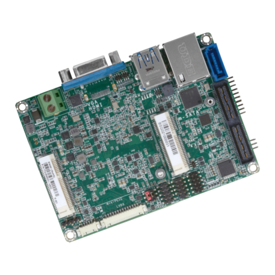
Chapter 2 Chapter 2 - Hardware Installation Board Layout mSATA Mini PCIe Top View Bottom View Chapter 2 Hardware Installation www.dfi.com... -
Page 9: Block Diagram
USB 2x (Line-out, Mic-in) SMBus Digital I/O 8-bit E I/O:DDI, PCIe 2x (Opt.) USB3.0 2x, LPC SMBus SMBus, SATA (Opt.) Line-out (Opt.) LPC Bus 3.04 RS-232/422/485 1x Super IO RS-232 1x with WDT H/W Monitor Chapter 2 Hardware Installation www.dfi.com... -
Page 10: System Memory
Before powering-on the system, make sure that the power settings of JP1 match the LCD panel’s specification. Selecting the incorrect voltage will seriously damage the LCD panel. • One 204-pin SODIMM up to 8GB • Single Channel DDR3L 1600MHz Chapter 2 Hardware Installation www.dfi.com... -
Page 11: Rear Panel I/O Ports
This 2-pin terminal block provides a maximum of 100W/120W power and is considered a low power solution. Connect a DC power cord to this terminal block. Using a voltage more than the recommended range may fail to boot the system or cause damage to the system board. Chapter 2 Hardware Installation www.dfi.com... -
Page 12: Graphics Interfaces
Configure the onboard LAN in the “ACPI Configuration” submenu of the Advanced menu in the BIOS. Refer to Chapter 3 for more information. Install the graphics driver. Refer to Chapter 4 for more information. Driver Installation Install the LAN drivers. Refer to Chapter 4 for more information. Chapter 2 Hardware Installation www.dfi.com... -
Page 13: Usb Ports
USB port cables to a connector. BIOS Settings Configure the onboard USB in the “USB Configuration” submenu of the Advanced menu in the BIOS. Refer to Chapter 3 for more information. Chapter 2 Hardware Installation www.dfi.com... -
Page 14: I/O Connectors
The front audio connector allows you to connect to line-out and mic-in jacks that are at the Pins Pin Name front panel of your system. DIO7 Driver Installation DIO6 Install the audio driver. Refer to Chapter 4 for more information. DIO5 DIO4 DIO3 DIO2 DIO1 DIO0 Chapter 2 Hardware Installation www.dfi.com... -
Page 15: Com (Serial) Ports
Configure the serial ports in the “Super IO” submenu of the Advanced menu in the BIOS. RAM) state, it will blink every 4 seconds. Refer to Chapter 3 for more information. Pin Pin Name Pin Pin Name HDD_LED Reset Button RESET- HDD-LED SUS_LED Power Button PWR-BTN PWR-LED V_LED Chapter 2 Hardware Installation www.dfi.com... -
Page 16: Sata (Serial Ata) Connector
Configure the Serial ATA drive in the Advanced menu (“SATA Configuration” submenu) of the It can expand the system’s internal I/O connectivity. Please refer to the following table for pin BIOS. Refer to Chapter 3 for more information. assignment. Chapter 2 Hardware Installation www.dfi.com... -
Page 17: E I/O Connector
USB_SSRX0- USB_SSTX1- AUD_GND LINE_JD LINE1_L LINE1_R USB_SSTX0+ NPTH NPTH USB_SSTX0- Note: DFI board's E I/O connector: SATA0_RX+ Manufacturer: Samtec SATA0_RX- Part No: QSE-040-01-L-D-A-K-TR Description: Board-to-board connector, 80 pin, 0.8mm (pitch), 3.25mm (height), PCIE_WAKE# SMT type, 180 degree SATA0_TX+ SATA0_TX- SMB_STB_CK... -
Page 18: Lvds Lcd Panel Connector
Part No: 0110-3221140 Description: Wafer connector, 14 pin, 1.25mm (pitch), 3.45mm (height), SMT type, LCD/Inverter power 90 degree 2. DFI board's LCD/Inverter power connector: Manufacturer: E-call Part No: 0110-3221050 Description: Wafer connector, 5 pin, 1.25mm (pitch), 3.45mm (height), SMT type,... -
Page 19: Smbus Connector
The System Management Bus (SMBus) connector is used to connect SMBus devices. It is a multiple device bus that allows multiple chips to connect to the same bus and enable each one to act as a master by initiating data transfer. Chapter 2 Hardware Installation www.dfi.com... -
Page 20: Chapter 3 - Bios Setup
“Press DEL to run setup” will appear on the screen. If the message that field and press <Enter>. disappears before you respond, restart the system or press the “Reset” button. You may also restart the system by pressing the <Ctrl> <Alt> and <Del> keys simultaneously. Chapter 3 BIOS Setup www.dfi.com... -
Page 21: Insyde Bios Setup Utility
Main Advanced Security Boot Exit This is the help for the Project Name BW051 X64 hour, minute, second BIOS Version 64.27A field. Valid range is from 0 to 23, 0 to 59, 0 to 59. Processor Type Intel(R) Atom(TM) x5-E8000 CPU @ 1.04GHz... - Page 22 TDP. Note: For the “After G3” setting to take effect, make sure that the "AC Power Loss” op- tion is set to “Always on” in “SIO FINTEK81803 ” of the “Advanced” menu. Chapter 3 BIOS Setup www.dfi.com...
- Page 23 <24 Bit> Dimming Control <PWM Mode> LCD Panel Type 800x480 800x600 1024x768 1366x768 1024x600 1280x800 Help ↑/↓ Select Item F5/F6 Change Values Setup Defaults Exit ←/→ Select Item Enter Select SubMenu Save and Exit Chapter 3 BIOS Setup www.dfi.com...
- Page 24 Setup Defaults Exit ←/→ Select Item Enter Select SubMenu Save and Exit Audio Controller Set to enable or disable the onboard Azalia controller. Disabled Azalia will be unconditionally disabled. Enabled Azalia will be unconditionally enabled. Chapter 3 BIOS Setup www.dfi.com...
- Page 25 The mode selection determines how the SATA controller(s) operates. AHCI Mode This option allows the Serial ATA devices to use AHCI (Advanced Host Controller Inter- face). Serial ATA Port 0, and 1 Enable or disable each serial ATA port. Chapter 3 BIOS Setup www.dfi.com...
- Page 26 Enable or disable the PCI Express Root Port. PCIe Speed Select the speed of the PCI Express Root Port: Gen1 or Gen2. Help ↑/↓ Select Item F5/F6 Change Values Setup Defaults Exit ←/→ Select Item Enter Select SubMenu Save and Exit Chapter 3 BIOS Setup www.dfi.com...
- Page 27 ® Configure the settings of the system’s serial ports. Disable Disable this serial port Enable Enable this serial port Type Choose the serial port type from RS232, RS422 or RS485 for COM port 2 only. Chapter 3 BIOS Setup www.dfi.com...
- Page 28 Set the AC power loss to Always off or Always on. When set to Always off, the sys- tem’s status will be power-off after an AC power loss event. When set to Always on, the system’s status will be power-on after an AC power loss event. Chapter 3 BIOS Setup www.dfi.com...
-
Page 29: Security
Disable or enable PXE boot to LAN. Set Supervisor Password USB Boot Set the administrative password. The length of the password must be greater than one character. Enable or disable the booting to USB boot devices. Chapter 3 BIOS Setup www.dfi.com... -
Page 30: Exit
Please do not remove the AC power Insyde H20FFT (Flash Firmware Tool) Version (SEG) 100.00.08.10 Copyright(c) 2012 - 2016, Insyde Software Corp. All Rights Reserved. Initializing Current BIOS Model name: BW051 New BIOS Model name: BW051 Help ↑/↓ Select Item... -
Page 31: Notice: Bios Spi Rom
When the BIOS IC needs to be replaced, you have to populate it properly onto the system board after the EEPROM programmer has been burned and follow the technical person's instructions to confirm that the MAC address should be burned or not. Chapter 3 BIOS Setup www.dfi.com... -
Page 32: Chapter 4 - Supported Software
If after inserting the DVD, “Autorun” did not automatically start (which is, the Mainboard Utility DVD screen did not appear), please go directly to the root directory of the DVD and double- click “Setup”. For Windows 10 Chapter 4 Supported Software www.dfi.com... -
Page 33: Intel Chipset Software Installation Utility
Intel chipset can be recognized and configured properly in the system. To install the utility, click “Intel Chipset Software Installation Utility” on the main menu. 1. Setup is ready to install the utility. Click Next. 2. Read the license agreement then click Yes. Chapter 4 Supported Software www.dfi.com... -
Page 34: Intel Graphics Drivers
1 to 2 minutes (while WinSAT is running) before the Windows 7/Windows 8.1/Windows 10 desktop appears. The “blank screen” period is the time Windows is testing the graphics performance. 2. Read the license agreement then click Yes. Chapter 4 Supported Software www.dfi.com... -
Page 35: Audio Drivers
Restarting the system will allow the new software installation to take effect. 5. Click “Yes, I want to restart this computer now” then click Finish. Restarting the system will allow the new software installation to take effect. Chapter 4 Supported Software www.dfi.com... -
Page 36: Intel Lan Drivers
1. Setup is ready to install the driver. Click Next. 5. After completing installa- tion, click Finish. 2. Click “I accept the terms in the license agreement” then click “Next”. 3. Select the program featuers you want installed then click Next. Chapter 4 Supported Software www.dfi.com... - Page 37 “Next.” 2. The update is installed 2. The step shows the now. components which will be installed. Then, Click Next. 3. Click “Restart Now“ to restart your computer when the installation is complete. Chapter 4 Supported Software www.dfi.com...
- Page 38 If you are using Windows 7, you need to access the operating system as an administrator to be able to install the utility. 1. Setup is ready to install the driver. 4. Click “Finish“ when the installation is complete. 2. Click “Next” to continue. Chapter 4 Supported Software www.dfi.com...
- Page 39 “I accept the terms tion, click “Finish”. in the license agreement”. Click “Next”. 4. The wizard is ready to begin installation. Click “Install”. 5. Please wait while the program features are being installed. Chapter 4 Supported Software www.dfi.com...
- Page 40 Note: The screenshot displayed above is for illustrative purpose only, and may not resemble the actual screen. The BW051 HW Utility features the following tabs: Information, HW Health, HW Healthset, Watchdog, DIO and Backlight. Click on the tabs to access information about the board.
- Page 41 4. Setup is currently installing the driver. After installation has com- pleted, click Next. 2. Read the license agreement care- fully. Click “I accept the terms in the cense Agreement” then click Next. 5. After completing installation, click Finish. Chapter 4 Supported Software www.dfi.com...
- Page 42 Chapter 4 Chapter 4 3. Read the file information then click 5. Setup is now installing the Next. driver. 4. Setup is ready to install the driver. 6. Click Finish. Click Next. Chapter 4 Supported Software www.dfi.com...
- Page 43 To install the reader, click “Adobe Acrobat Reader 9.3” on the main menu. 1. Click Next to install or click Change Destination Folder to select another folder. 2. Click Install to begin installa- tion. 3. Click Finish to exit installation. Chapter 4 Supported Software www.dfi.com...
-
Page 44: Appendix A - Troubleshooting Checklist
4. There is not enough space left on the diskette. Use another diskette with adequate storage 4. Adjust the brightness of the display by turning the monitor’s brightness control knob. space. Appendix A Troubleshooting Checklist www.dfi.com... -
Page 45: Hard Drive
Nothing happens when a key on the keyboard was pressed. 1. Make sure the keyboard is properly connected. 2. Make sure there are no objects resting on the keyboard and that no keys are pressed dur- ing the booting process. Appendix A Troubleshooting Checklist www.dfi.com...
Need help?
Do you have a question about the BW051 and is the answer not in the manual?
Questions and answers