
Related Manuals for ADLINK Technology HPERC-IBR-MC


Summary of Contents for ADLINK Technology HPERC-IBR-MC
- Page 1 HPERC-IBR-MC/MH High Performance Extreme Rugged Computer System User’s Manual 1.00 Manual Rev.: December 20, 2016 Revision Date: 50-1Z178-1000 Part No: Advance Technologies. Automate the World.
- Page 2 Revision History Revision Reason for Change Date 1.00 Initial release 20-12-2016 Revision History...
-
Page 3: Preface
Audience This manual provides reference only for computer design engineers, including but not limited to hardware and software designers and applications engineers. ADLINK Technology, Inc. assumes you are qualified to design and implement prototype computer equipment. Preface... - Page 4 This page intentionally left blank. Preface...
-
Page 5: Table Of Contents
HPERC-IBR-M Table of Contents Revision History........................ii Preface ..........................iii List of Figures ........................vii List of Tables ........................ix 1 HPERC-IBR-M Setup ......................1 About the HPERC-IBR-M....................... 1 Using this Guide........................1 Requirements......................... 1 Device/Peripheral Connections....................1 Specifications......................... 2 Block Diagram........................ - Page 6 3.3.5 Intel Rapid Start Technology................... 29 3.3.6 Intel TXT(LT) Technology ....................30 3.3.7 PCH-FW Configuration ....................30 3.3.8 Intel Anti-Theft Technology Configuration............... 30 3.3.9 USB..........................31 3.3.10F81216 Second Super IO ....................31 3.3.11Super IO.......................... 32 3.3.12H/W Monitor ........................32 3.3.13Serial Port Console ......................33 3.3.14AMI Graphic Output Protocol Policy................
-
Page 7: List Of Figures
HPERC-IBR-M List of Figures Figure 1-1: HPERC-IBR-M Block Diagram..................4 Figure 1-2: i7-3517UE Peak In-Rush Current and Duration (without GPGPU) ........5 Figure 1-3: HPERC-IBR-M Unit with Accessories ................7 Figure 1-4: Top and Front Views of “MH” Enclosure with Mounting Dimensions .......9 Figure 1-5: Top and Front Views of “MC”... - Page 8 This page intentionally left blank. viii List of Figures...
-
Page 9: List Of Tables
HPERC-IBR-M List of Tables Table 1-1: HPERC-IBR-M Specifications....................2 Table 1-2: System Power Requirements (without GPGPU) ...............5 Table 1-3: System Power Requirements (with GPGPU) ..............6 Table 1-4: Environmental Requirements ....................6 Table 1-5: I/O Panel Connectors (Refer to Figure 1-7 for connector locations.).......13 Table 1-6: P1 Military DC Power In Connector Signals ..............13 Table 1-7: P2 Military Connector Signals..................15 Table 1-8: P3 Connector Pin Signals....................18... - Page 10 This page intentionally left blank. List of Tables...
-
Page 11: Hperc-Ibr-M Setup
HPERC-IBR-M HPERC-IBR-M Setup 1.1 About the HPERC-IBR-M The HPERC products are intended for users of embedded systems requiring long life-cycles, configuration control, and ruggedness in hardened military packages. HPERC models feature Extreme Rugged™ computer boards available with varieties of processors and memory. An optional operating system (OS) can be pre-loaded onto an optional internal storage device (two 2 ½"... -
Page 12: Specifications
1.5 Specifications VITA 75 VITA Standards • Form Factor: VITA-75.22 Conductive Coldplate • Dimension: 223.38(L) x 177.8(W) x 68.7(H) mm (with mounting brackets) • Weight: 3.12 kg Mechanical • Form Factor: VITA-75 Finned Passive Convection • Dimension: 304.8(L) x 150(W) x 101.95(H) mm (with mounting brackets) •... - Page 13 HPERC-IBR-M • Baseplate Point Extreme Rugged • -40°C to +85°C (i7-3517UE) • -40°C to +80°C (i7-3612QE) • Coldplate conduction Operating Temperature • VITA 75.22 mount • Ambient:40°C to +70°C at 1 atm air • Heatsink (free air convection) • VITA 75.21 mount -55°C to 85°C Storage Temperature Input: +10 to +36VDC input...
-
Page 14: Block Diagram
1.6 Block Diagram DDR3 1333MHz with 64bit +8bit ECC (2 Ranks) PCIe x16 Link Intel® Core™ i7 Connector Processor DDR3 1333MHz with 64bit +8bit ECC SO-DIMM PCI-32bit (2 Ranks) XIO2001 33/66MHz PEX 8618 PCIe-to-PCI PCIe x1 PCIe Bridge Switch (1 & 2) PCIe x1 Mini-PCIe 2x SATA... -
Page 15: Power Specifications (Without Gpgpu)
HPERC-IBR-M 1.7 Power Specifications (without GPGPU) Table 1-2 defines the current draw values of the HPERC-IBR-M, featuring either the 3517UE, or 3612QE i7 CPUs. The table captures In-Rush, Idle, and Burn-In-Test (BIT) currents. Table 1-2 lists the current draw values of the HPERC-IBR-M. Parameter 1.7GHz CPU (i7-3517UE) 2.1GHz CPU (i7-3612QE) -
Page 16: Power Specifications (With Gpgpu)
1.8 Power Specifications (with GPGPU) Table 1-3 defines the current draw values of the HPERC-IBR-M, 3612QE i7 CPUs. The table captures Idle, and Burn-In-Test (BIT) currents. Table 1-3 lists the current draw values of the HPERC-IBR-M Configuration CPU: Intel® Core™ i7-3612QE Processor (6M cache, up to 2.10 GHz, Max Turbo Fre- quency 3.1GHz) Memory: Micro PC3-10700 DDR3 1600 8G x2 (onboard and slot), total 16GB Storage: Transcend 256G TS256GSSD370I 2.5"... -
Page 17: What's In The Box
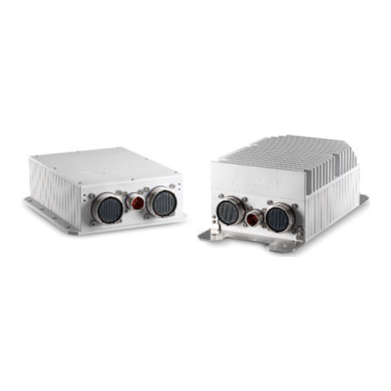
HPERC-IBR-M 1.10 What’s in the Box The Contents List identifies the items in the shipping box for the HPERC-IBR-M Unit and HPERC-IBR-M Accessories (sold separately.) See Figure 1-3. HPERC-MH Cooling Fins (pre-installed on MH version only) HPERC-MC Mounting Brackets Cold Plate (pre-installed on MC version, only) HPERC Accessories (sold separately) -
Page 18: Setup Steps
Torque Values Material: Stainless Steel Material: Stainless Steel Material: SCM3 (SCM435) Nominal Diameter A2-70 and A4-70 A2-80 and A4-80 Strength Grade: 12.9 M6 (HPERC-IBR-MC) 7.6 Nm 11.1 Nm 13.83 Nm M8 (HPERC-IBR-MH) 18.4 Nm 26.7 Nm 33.34 Nm HPERC-IBR-M Setup... -
Page 19: Figure 1-4: Top And Front Views Of "Mh" Enclosure With Mounting Dimensions
HPERC-IBR-M HPERC-IBR-MH Figure 1-4: Top and Front Views of “MH” Enclosure with Mounting Dimensions HPERC-IBR-M Setup... -
Page 20: Figure 1-5: Top And Front Views Of "Mc" Enclosure With Mounting Dimensions
HPERC-IBR-MC The HPERC-IBR-MC unit coldplate is flat to a tolerance of ±0.1 mm across the diagonal. It is recom- mended that the surface on which the HPERC-IBR-MC will be mounted is flat to a tolerance of ±0.15 mm across the diagonal. -
Page 21: Figure 1-6: Bottom View Of "Mc" Enclosure With Mounting Holes
• Mounting holes “A” and “B” are shown below in Figure 1-6. Note the surface/wall mounting or heat recommended torque values and maximum depth of hole “B”. sink (HPERC-IBR-MC only Mounting Hole “A” Size: M4 threaded Mounting Hole “B” Size: M4 threaded, max. depth 7mm Maximum Torque: 30 Kgf-cm (2.85 N-m) -
Page 22: Connecting Peripherals
• Connect the VGA or LCD display to the appropriate connector on the corresponding breakout cable. HPERC-IBR-MH P2 Military P1 DC P3 Military Connector Connector Power In HPERC-IBR-MC Figure 1-7: Front View of HPERC-IBR-M I/O Panel HPERC-IBR-M Setup... -
Page 23: P1 Military Dc Power In Connector
HPERC-IBR-M Control/Connector Description P1 DC Power In This Military Power connector accepts DC voltages from an external source. NOTE: This connector is manufactured by Amphenol. P2 Military Connector This military connector provides signals for Ethernet Ports, USB 2.0, Serial Ports, Reset Switch, Ethernet LEDs, Power LED, SATA Activity LED, UNDIO, Power Switch, Audio In/Out. -
Page 24: P2 And P3 Military Connector
1.16 P2 and P3 Military Connector The following two tables define the signals and signal maps of the two military I/O connectors (P2 and P3) on the HPERC-IBR-M. Each table lists the P2 or P3 pin numbers, the signal names and descriptions and the corresponding pins of the internal IO boards (HIBR and Interface Board.) Figure 1-9 provides the number and location of each pin on the two military connectors. -
Page 25: 1P2 Pin Definitions
HPERC-IBR-M 1.16.1 P2 Pin Definitions Table 1-7 Provides the pin definitions and signal maps for the P2 Military Connector. Interface Signal Signal Description Gigabit Ethernet 1 GbE2_MDI0_P Ethernet1 MDI0 Positive Gigabit Ethernet 1 GbE2_MDI1_N Ethernet1 MDI1 Negative Gigabit Ethernet 1 GbE2_MDI1_P Ethernet1 MDI1 Positive Ground... - Page 26 Interface Signal Signal Description Ground Ground Power +5 Volts Power Power +5 Volts Power Ground Ground Ground Ground User Defined IO UDNIO11 User Input/Output Port 11 User Defined IO UDNIO12 User Input/Output Port 12 Ground Ground Ground Ground User Defined IO UDNIO13 User Input/Output Port 13 User Defined IO...
- Page 27 HPERC-IBR-M Interface Signal Signal Description Power P3V3_S +3.3 Volts Standby Ground Ground Power Switch PWERBTN_HDR Powers on the system USB 2.0, Port 9 USB_PWR9 USB 2.0 +5V Power USB 2.0, Port 9 USB_N9 USB 2.0 Data Negative USB 2.0, Port 9 USB_P9 USB 2.0 Data Positive Ground...
-
Page 28: 2P3 Pin Definitions
1.16.2 P3 Pin Definitions Table 1-8 Provides the pin definitions and signal maps for the P3 Military Connector. Interface Signal Signal Description VGA_VSYNC Vertical Sync Ground Ground Ground Ground VGA_DDC_SCL Display Data Channel - Serial Clock VGA_DDC_SDA Display Data Channel - Serial Data Ground Ground... - Page 29 HPERC-IBR-M Interface Signal Signal Description Ground Ground Gigabit Ethernet 2 GbE3_MDI2_N Ethernet2 Negative Gigabit Ethernet 2 GbE3_MDI2_P Ethernet2 Positive Ground Ground Gigabit Ethernet 2 GbE3_MDI3_N Ethernet3 Negative Gigabit Ethernet 2 GbE3_MDI3_P Ethernet3 Positive Ground Gigabit Ethernet 2 GbE3_MDI1_N Ethernet1 Negative Gigabit Ethernet 2 GbE3_MDI1_P Ethernet1 Positive...
- Page 30 Interface Signal Signal Description DVI 2 DDIC_N2 Digital Display Interface Port C, TMDS Data 0 Negative Ground Ground Ground Ground DVI 2 DDIC_P1 Digital Display Interface Port C, TMDS Data 1 Positive DVI 2 DDIC_N1 Digital Display Interface Port C, TMDS Data 1 Negative DVI 2 DDIC_P0...
- Page 31 HPERC-IBR-M Interface Signal Signal Description Power +5 Volts Power, PCIe_ETH_2/5_LED2 Ground Ground Ground Ground Gigabit Ethernet 3 GbE4_MDI1_N Ethernet1 Negative Gigabit Ethernet 3 GbE4_MDI1_P Ethernet1 Positive Gigabit Ethernet 3 GbE4_MDI0_N Ethernet0 Negative Gigabit Ethernet 3 GbE4_MDI0_P Ethernet0 Positive Ground Ground Gigabit Ethernet 3 GbE4_MDI2_N Ethernet2 Negative...
-
Page 32: Applying Power To The Hperc-Ibr-M
1.17 Applying Power to the HPERC-IBR-M • Connect the AC Mating Cable to the AC Adapter (options.) See 1) Follow these steps to Figure 1-3. apply power to the • Plug in the DC Cable Connector from the AC Adapter (option) to HPERC-IBR-M. -
Page 33: Internal Components
HPERC-IBR-M Internal Components The HPERC-IBR-M enclosure allows installation and removal of components including Solid State Drives (SSDs), SD memory card, PCI/104-Express expansion module, SODIMM memory, and Mini PCIe Card. Opening and resealing any of the openings on the HPERC-IBR-M enclosure may compromise the IP67 ingress rating performance of the system. - Page 34 This page intentionally left blank. Internal Components...
-
Page 35: Bios Setup
HPERC-IBR-M BIOS Setup This chapter provides information on how to read information from and configure the BIOS Setup utility of the HPERC-IBR-M. Menu Structure This section presents the primary menus of the BIOS Setup Utility. Use the following table as a quick reference for the contents of the BIOS Setup Utility. -
Page 36: Main Menu
Main Menu The Main Menu provides read-only information about your system and also allows you to set the System Date and Time. Refer to the tables below for details of the submenus and settings. 3.2.1 BIOS Information Feature Options Description BIOS Vendor Info only Vendor... -
Page 37: System Date And Time
HPERC-IBR-M 3.2.5 System Date and Time Feature Options Description System Date Weekday, MM/DD/YYYY Requires the alpha-numeric entry of the day of the week, day of the month, calendar month, and all 4 digits of the year, indicating the century and year (Fri XX/XX/20XX) System Time HH/MM/SS... -
Page 38: Cpu
3.3.3 Feature Options Description Info only CPU Signature Info only Display CPU Signature Microcode Patch Info only Display CPU Microcode version Max CPU Speed Info only Display CPU Max frequency Min CPU speed Info only Display CPU Min frequency CPU Speed Info only Display CPU frequency Processor Cores... -
Page 39: Sata
HPERC-IBR-M 3.3.4 SATA Feature Options Description SATA Info only SATA Mode Selection Determines how SATA Controller(s) operate. AHCI RAID SATA Test Mode Disabled Test mode Enabled / Disabled Enabled SATA Controller Speed Indicates the maximum speed the SATA controller Default Gen1 can support. -
Page 40: Intel Txt(Lt) Technology
3.3.6 Intel TXT(LT) Technology Feature Options Description Intel TXT(LT) Configuration Info only Intel TXT(LT) Support Enables or Disables Intel(R) TXT(LT) support. Disabled Enabled 3.3.7 PCH-FW Configuration Feature Options Description ME FW Version Info only ME FW Mode Info only ME FW Type Info only ME FW SKU Info only... -
Page 41: Usb
HPERC-IBR-M 3.3.9 Feature Options Description USB Module version Info only USB Devices: Info only Legacy USB Support Enables Legacy USB support. Enabled Disabled XHCI Hand-off This is a workaround for OSes without XHCI Enabled Disabled hand-off support. EHCI Hand-off Enabled This is a workaround for OSes without EHCI hand-off support. -
Page 42: 11Super Io
3.3.11 Super IO Feature Options Description SCH3114 Super IO Configuration Info only Serial Port 0 Configuration Submenu Set Parameters of Serial Port 0. Serial Port 1 Configuration Submenu Set Parameters of Serial Port 1. Serial Port 2 Configuration Submenu Set Parameters of Serial Port 2. Super IO >... -
Page 43: 13Serial Port Console
HPERC-IBR-M 3.3.13 Serial Port Console Feature Options Description Serial Port Console Info only COM0 Info only Console Redirection Console Redirection enable or disable. Disabled Enabled Console Redirection Settings Submenu The settings specify how the host computer and the remote computer (which the user is using) will exchange data. - Page 44 Serial Port Console > Console Redirection Settings Feature Options Description COM0 Info only Console Redirection Settings Terminal Type VT100 VT100: ASCII char set. VT100+: Extends VT100 to support color, VT100+ VT-UTF8 function keys, etc. VT-UTF8: Uses UTF8 ANSI encoding to map Unicode chars onto 1 or more bytes.
-
Page 45: 14Ami Graphic Output Protocol Policy
HPERC-IBR-M 3.3.14 AMI Graphic Output Protocol Policy Feature Options Description Output Select Info only Output interface Output Select Info only Output interface Output Select Info only Output interface Output Select Info only Output interface Output Select Info only Output interface Output Select Info only Output interface... -
Page 46: 17Cpu Ppm Configuration
3.3.17 CPU PPM Configuration Feature Options Description CPU PPM Configuration Info only EIST Enable/Disable Intel SpeedStep. Enabled Disabled Turbo Mode Enable/Disable Turbo Mode. Enabled Disabled CPU C3 Report Enable/Disable CPU C3(ACPI C2) report to OS. Enabled Disabled CPU C6 Report Enable/Disable CPU C6(ACPI C3) report to OS. -
Page 47: System Agent Configuration
HPERC-IBR-M PCH-IO Configuration > PCI Azalia Configuration Feature Options Description Azalia Disabled Control Detection of the Azalia device. Disabled = Azalia will be unconditionally disabled Enabled = Enable Azalia will be unconditionally Enabled Auto = Azalia will be enabled if present, disabled otherwise. - Page 48 System Agent Configuration > Graphics Configuration > LCD Control Feature Options Description Primary IGFX Boot Display Vbios Default Select the Video Device which will be activated during POST. EFP3 EFP2 LFP2 Display Port DDI function choose to Display Port or HDMI. DDI Function choose HDMI >>Hardware: Spread is controlled by chip;...
-
Page 49: Boot
HPERC-IBR-M Boot 3.5.1 Boot Configuration Feature Options Description Boot Configuration Info only Setup Prompt Timeout Number of seconds to wait for setup activation key. 65535 (0xFFFF ) means indefinite waiting. Bootup NumLock State Select the keyboard NumLock state. Quiet Boot Enable or disables Quiet Boot option. -
Page 50: Security
Boot Configuration > CSM Configuration Feature Options Description Launch CSM Enable/Disable CSM Support. Enabled Disable Boot option filter This option controls Legacy/UEFI ROMs priority. UEFI and Legacy Legacy only UEFI only Launch PXE OpROM policy Do not launch Controls the execution of UEFI and Legacy PXE UEFI only OpROM Legacy only... -
Page 51: Safety Instructions
HPERC-IBR-M Safety Instructions For user safety, please read and follow all instructions, WARNINGS, CAUTIONS, and NOTES marked in this manual and on the associated equipment before handling/operating the equip- ment. 1. Read these safety instructions carefully. 2. Keep this user's manual for future reference. 3. - Page 52 This page intentionally left blank. Safety Instructions...
-
Page 53: Getting Service
San Jose, CA 95138, USA Tel: +1-408-360-0200 Toll Free: +1-800-966-5200 (USA only) Fax: +1-408-360-0222 Email: info@adlinktech.com ADLINK Technology (China) Co., Ltd. 300 Fang Chun Rd., Zhangjiang Hi-Tech Park Pudong New Area, Shanghai, 201203 China Tel: +86-21-5132-8988 Fax: +86-21-5132-3588 Email: market@adlinktech.com...
Need help?
Do you have a question about the HPERC-IBR-MC and is the answer not in the manual?
Questions and answers