
Related Manuals for Binks E2-60


Summary of Contents for Binks E2-60
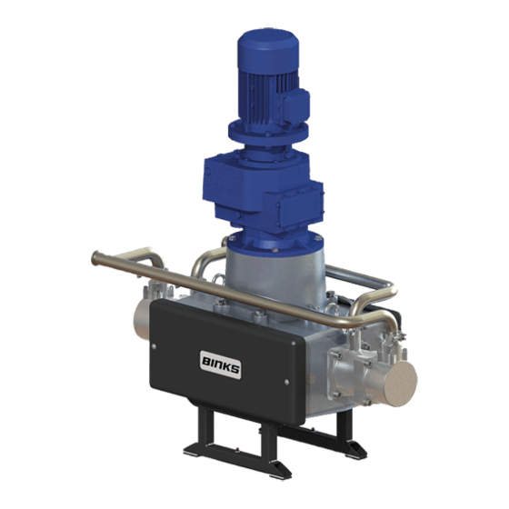
- Page 1 Service Manual E2-60 Electric Drive Pump • 104085 (EU Model) • 104086 (USA Model) • 104087 (Japan Model) 77-3228 R3.3 www.carlisleft.com...
-
Page 2: Eu Declaration Of Conformity
Product Description / Object of Declaration: Electric Pump E2, E4, EV2 This Product is designed for use with: Solvent and Water based materials Suitable for use in hazardous area: Zone 1 Protection Level: II 2 G X IIB T4 (Pump) II 2 G Exd/Exde IIB T4 IP55 (Motor) CE0722 II 2 GD ck T4 (Gearbox) Notified body details and role:... - Page 3 In this part sheet, the words WARNING, CAUTION and NOTE are used to emphasize important safety information as follows: WARNING CAUTION NOTE Hazards or unsafe practices which could result in Hazards or unsafe practices which could result in Important installation, operation or maintenance severe personal injury, death or substantial property minor personal injury, product or property information.
-
Page 4: Specification
* Pressure when used in 'Smart Mode' (Closed Loop Pressure Mode) Reduce Maximum working pressure by 2 bar [29 psi] when using in Open Loop Flow Mode e.g. E2-60 Maximum Set Pressure of 18 bar to operate Pump on a 24/7 basis 77-3228 R3.3 4/36 www.carlisleft.com... -
Page 5: Dimensions And Mounting Details
DIMENSIONS AND MOUNTING DETAILS M6 HEX. Head screw for pump earth grounding; the Pump Frame must be wired to a suitable earth ground to ensure that there is no possibility of static build up. 77-3228 R3.3 5/36 www.carlisleft.com... -
Page 6: Installation
INSTALLATION The Pump Units are designed for location in Zone 1 Hazardous areas, ATEX Category 2. Electrical connections must be in accordance with Local Regulations for installation in Hazardous Areas. It is recommended that a Local Control Box is positioned in close proximity to the pump, as a convenient local Start / Stop facility and Junction box. -
Page 7: Electric Motor
INSTALLATION Electric Motor The motor must be wired to provide a clockwise direction of the cam. Electric Motors for hazardous areas are specially designed to comply with official regulations concerning the risk of explosion. If improperly used, badly connected, or altered no matter how minor, their reliability could be in doubt. Standards relating to the connection and use of electrical apparatus in hazardous areas must be taken into consideration. - Page 8 INSTALLATION • Attach suitable flexible hoses to the inlet and outlet connections. e.g., • Suction - Ø38 I.D. [-1 to 10 bar working pressure] • Outlet - Ø32 - 38 I.D. [20 bar working pressure] • Ensure adequate air space around the Pump for maintenance and electric motor cooling requirements. •...
-
Page 9: System Operation
SYSTEM OPERATION Before starting:- • Ensure all electrical and mechanical connections are correctly made. • All required interlocks are tested and operational. • Suitable material for pumping is available at the suction hose. • The outlet connection is not blocked or isolated by any valves. •... - Page 10 PARTS LIST - Pump Assembly ITEM PART NUMBER DESCRIPTION REMARKS 193710 E2-60 MECHANICAL ASSY EU MODEL 192684 3.0KW ATEX MOTOR ELECTRIC MOTOR USA MODEL 192685 (Not Shown) GEARBOX JAPAN MODEL 192819 (Not Shown) EU MODEL 192686 ATEX GEARBOX GEARBOX USA MODEL...
- Page 11 GREASE LOCTITE TORQUE MAINTENANCE ORDER (Reverse for assembly) GREASE INTERNAL (AGMD-010) 77-3228 R3.3 11/36 www.carlisleft.com...
- Page 12 PARTS LIST - PRV and Manifold Assembly ITEM PART NUMBER DESCRIPTION REMARKS 104168 1.5'' PRESSURE RELIEF VALVE 192008 1.5'' SANITARY GASKET 192009 SANITARY CLAMP 193746 1.5'' ELBOW INLET MANIFOLD 193747 OUTLET MANIFOLD 193748 194591 1.5'' ELBOW 194593 1.5'' ELBOW GREASE LOCTITE TORQUE MAINTENANCE ORDER...
- Page 13 PARTS LIST - Mechanical Assembly ITEM PART NUMBER DESCRIPTION REMARKS M8 NYLOC NUT 163161 M12 WASHER 164470 M16 WASHER 165097 M16 SPRING WASHER 165100 M8 SPRING WASHER 165108 Ø10 SPRING WASHER 165123 Ø8 WASHER 165134 M12 SPRING WASHER 165137 164469 M12 x 40 HEX HEAD CAP SCREW 165371 M16 x 60 SCREW...
- Page 14 Parts list continued. ITEM PART NUMBER DESCRIPTION REMARKS 193430 MAIN BODY MACHINING 193434 CARRIAGE SPRING 193442 LINEAR SPRING PIN 193449 LINEAR BEARING ROD 193454 LEAK DETECTION HOSE ASSY 193455 CARRIAGE ASSEMBLY 193457 SHAFT CLAMP ASSY 193698 Ø50 COUPLING SPACER 193750 ADAPTER 193796...
- Page 15 GREASE LOCTITE TORQUE MAINTENANCE ORDER (Reverse for assembly) GREASE INTERNAL (AGMD-010) ** Tighten bolts holding carriage ends once pump is fully assembled. 77-3228 R3.3 15/36 www.carlisleft.com...
- Page 16 GREASE LOCTITE TORQUE MAINTENANCE ORDER (Reverse for assembly) GREASE INTERNAL (AGMD-010) NOTE: Part No. 5 To be pressed into housing using tool 502510 Part No. 6 To be pressed into housing using tool 502511 Part No. 9 To be tightened using tool 502509 Part No.
- Page 17 PARTS LIST - Bell Housing & Shaft Assemblies ITEM PART NUMBER DESCRIPTION REMARKS 163951 M6 x 16 CAP HEAD SCREW 163952 M6 x 20 CAP HEAD SCREW 192616 TOP BEARING CAP 192617 BOTTOM BEARING CAP 192639 Ø50 x Ø100 x 44.4 BALL BEARING 192640 Ø45 x Ø100 x 36 BALL BEARING 192644...
- Page 18 Parts list continued. ITEM PART NUMBER DESCRIPTION REMARKS 193437 BOTTOM BEARING HOUSING 194511 SHAFT ASSEMBLY 193440 CONSTANT VELOCITY CAM 193436 TOP SHAFT 193435 BOTTOM SHAFT 165571 M10 x 70 CAP HEAD SCREW 77-3228 R3.3 18/36 www.carlisleft.com...
- Page 19 PARTS LIST - Carriage Assembly ITEM PART NUMBER DESCRIPTION REMARKS 165123 M10 SPRING WASHER 165139 M20 SPRING WASHER 165947 CAP HEAD SCREW 166158 CIRCLIP 177011 M20 NYLOC NUT 177012 M10 x 25 CAP HEAD SCREW 192649 GREASE NIPPLE 192651 PLUG 192661 PUSH IN ELBOW 193103...
- Page 20 GREASE LOCTITE TORQUE MAINTENANCE ORDER (Reverse for assembly) GREASE INTERNAL (AGMD-010) 77-3228 R3.3 20/36 www.carlisleft.com...
-
Page 21: Parts List - Fluid Section
PARTS LIST - Fluid Section ITEM PART NUMBER DESCRIPTION REMARKS 160513 SPRING 164472 M8 x 25 SCREW 165077 M14 SPRING WASHER 165108 M8 SPRING WASHER 171788 1 3/8'' BALL 177032 M14 x 45 CAP HEAD SCREW 177033 M14 x 45 CAP HEAD SCREW 192505 Ø12.42 X 1.78 O-RING 192551... - Page 22 GREASE LOCTITE TORQUE MAINTENANCE ORDER (Reverse for assembly) GREASE INTERNAL (AGMD-010) 77-3228 R3.3 22/36 www.carlisleft.com...
- Page 23 PARTS LIST - Piston Assembly ITEM PART NUMBER DESCRIPTION REMARKS 160513 PISTON BALL CHECK SPRING 162805 Ø63.17 X 2.62 O-RING 162806 Ø107.62 X 2.62 O-RING 162807 Ø50.52 X 1.78 O-RING 171784 1.75'' BALL 192629 INLET SPRING KEEP 192631 SEAT 193652 Ø128 FLUID PISTON 193653 BALL CAGE...
- Page 24 PARTS LIST - Shaft & Bellows Assembly ITEM PART NUMBER DESCRIPTION REMARKS 192881 KNIFED BELLOWS 192887 RETAINING NUT 193445 BELLOWS SPACER 193452 PISTON SHAFT 193453 SHAFT SEAL 502682 BELLOWS POSITIONING TOOL TOOL 502681 BELLOWS ASSEMBLY SPIGOT TOOL Screw Item No. 6 (assembly spigot) onto the piston shaft (grease spigot with AMGD-010).
-
Page 25: General Maintenance
Maintenance General Maintenance The working life and thus the expected life prior to replacement of parts within a Paint Pump are greatly affected by three main factors: - • Abrasiveness of Fluid Pumped • Pump Duty Cycle • Fluid Pressure Output Requirement The two components which are more greatly affected by the above criteria than any other components in the pump are: The Main Piston Seal and the Cam Follower ;... -
Page 26: Maintenance Schedule
Maintenance Maintenance schedule Inspection Operation Daily Check for any fluid leakage Check for any excessive mechanical noise Weekly Check for excessive fluid pressure pulsation Check oil level within gearbox While running, apply (502375) grease to cam follower bearings, 8 strokes of a 3 Monthly standard ‘cartridge’... - Page 27 Maintenance - Gearbox WARNING Wait until the unit has cooled sufficiently after stopping and isolation. Gearbox Every 1000 hours verify the good condition of oil seals and gaskets Maintenance The gearbox is supplied factory fitted with oil and is a service free unit. However if seals start to leak and oil level is reduced, both the affected seal and oil need to be replaced as a general overhaul of the unit.
- Page 28 Maintenance - Motor WARNING Wait until the unit has cooled sufficiently after stopping and isolation. Electric Motors Maintenance of Ex Motors - are reported by EN 60079-17 standard, in particular:- • The electric connections must be correctly locked to avoid resistance-increases, with consequent contact overheating.
-
Page 29: Fault Finding
Fault Finding Mechanics Symptom Possible Cause Remedy Gearbox Output shaft does not Drive between shafts in the gear Return the unit for repair and rotate, even though the motor is unit interrupted replace gearbox running. Gearbox Oil leaking a) Defective gasket on gear unit a) Retighten screws on gear unit cover. -
Page 30: Fluid Section
Fault Finding Fluid Section Symptom Possible Cause Remedy a) Air entering the suction a) Check o-rings and hose hose/manifold connections b) Worn piston seals b) Replace piston seals. Pump will not ‘Prime’ c) Ball checks not seating correctly. c) Inspect, clean and/or replace balls and seats. - Page 31 Testing and Lubricating Testing and Lubricating after major overhaul WARNING Testing and Lubricating - Qualified personnel only Connect pump to paint system. Connect electric motor to a suitable electrical supply. Fit the gearbox vent plug. Turn on paint system and set back pressure regulator to zero. Turn the pump on at the local isolation mounted switch.
-
Page 32: Spare Parts List
Spare Parts List Recommended Replacement Spare Parts and Kits for E2-60 Pumps KIT No. PART NUMBER DESCRIPTION REMARKS 193440 CONSTANT VELOCITY CAM 192891 PISTON 193451 CAM FOLLOWER BEARING 193448 LINEAR BEARING 192881 BELLOWS (FLUID SECTION) 250632 FLUID SECTION SEAL KIT ... - Page 33 ACCESSORIES PART NUMBER DESCRIPTION REMARKS 192800 SMART CARD 502501 BPR CONTROL BOX 502483 ELECTRICAL PANEL FOR SINGLE PUMP OPERATION INC. SMART CARD 502373 GREASE GUN FOR CAM FOLLOWER (& MAIN BEARINGS) COLLET CONNECTOR 502514 GREASE GUN FOR LINEAR BEARINGS (300mm EXTENSION) HOOK CONNECTOR 502375 GREASE FOR CAM FOLLOWER (&...
- Page 34 ACCESSORIES PART NUMBER DESCRIPTION REMARKS 192450 M8 TORX SECURITY SCREWDRIVER FOR COVER FOC with a New Pump 502508 TOP BEARING LOCKNUT TOOL 502509 BOTTOM BEARING LOCKNUT TOOL 502510 TOP BEARING PRESS TOOL 502511 BOTTOM BEARING PRESS TOOL 502512 SHAFT ASSEMBLY TOOL 502681 BELLOWS ASSEMBLY TOOL 502682...
- Page 35 NOTES 77-3228 R3.3 35/36 www.carlisleft.com...
-
Page 36: Warranty Policy
© 2018 Carlisle Fluid Technologies, Inc. All rights reserved. Binks is part of Carlisle Fluid Technologies, a global leader in innovative finishing technologies. For technical assistance or to locate an authorized distributer, contact one of our international sales and customer support locations below.
Need help?
Do you have a question about the E2-60 and is the answer not in the manual?
Questions and answers