Table of Contents

Subscribe to Our Youtube Channel
Related Manuals for Binks E2-30


Summary of Contents for Binks E2-30
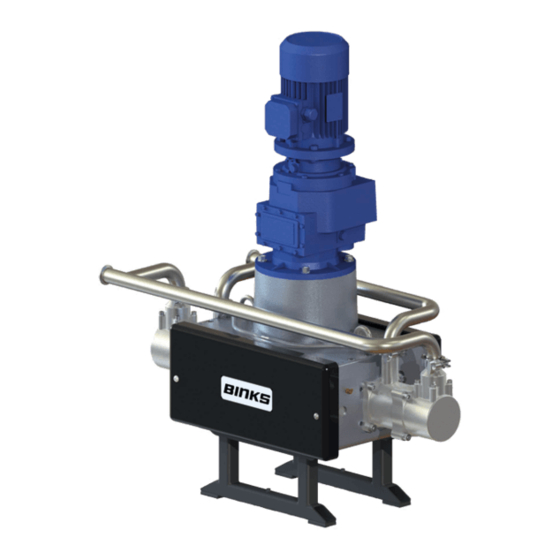
- Page 1 Instruction Manual E2-30 Electric Drive Pump • Model 107071 (EU Model) • Model 107074 (USA Model) • Model 107075 (Japan Model) E2-40 Electric Drive Pump • Model 107093 (EU Model) • Model 107094 (USA Model) • Model 107095 (Japan Model)
- Page 2 Justus-von-Liebig-Straße 31, 63128 Dietzenbach. DE EU Declaration of Conformity We: Binks declare that the above product conforms with the Provisions of Machinery Directive 2006/42/EC and the ATEX Directive 94/9/EC by complying with the following statutory documents and harmonized standards: - Machinery Safety Standards EN ISO 12100, EN ISO 4413, EN ISO 4414 &...
-
Page 3: Table Of Contents
Parts Lists – Fluid Section Assembly Maintenance - Assembly Procedure Maintenance – General Maintenance - Motor / Gearbox Maintenance - Fault Finding Maintenance – Testing / Lubrication / Draining Spare Parts Lists Accessories Page 3 of 40 Issue: 2.1 N:\Engineering\Manuals\Pump Unit E2-30 & 40 R2.1.doc... -
Page 4: General Description
AC frequency inverter between 20 and 80 HZ and can be adjusted infinitely within this working range. Complies with current relevant European and US Legislation Patents Granted Page 4 of 40 Issue: 2.1 N:\Engineering\Manuals\Pump Unit E2-30 & 40 R2.1.doc... -
Page 5: Operating Principle
Ball checks control the fluid flow into and out of the pressure chambers during these operations. Page 5 of 40 Issue: 2.1 N:\Engineering\Manuals\Pump Unit E2-30 & 40 R2.1.doc... - Page 6 If the main piston seal starts to pass fluid due to wear, any leakage passes into the inlet chamber. Suction Stroke Pressure Stroke Page 6 of 40 Issue: 2.1 N:\Engineering\Manuals\Pump Unit E2-30 & 40 R2.1.doc...
- Page 7 0.75 Litres (0.20 US Gall) E2-40 Nominal Flow Volume / Cycle 1.00 Litre (0.26 US Gall) E2-30 Fluid Output @ 20 HZ (10 cycles/min) 7.5 Litres / min (2.0 US Gall / min) E2-40 Fluid Output @ 20 HZ (10 cycles/min 10 Litres / min (2.64 US Gall / min)
-
Page 8: Dimensions And Mounting Details
Instruction Manual Dimensions and Mounting Details – Section 1.4 Page 8 of 40 Issue: 2.1 N:\Engineering\Manuals\Pump Unit E2-30 & 40 R2.1.doc... -
Page 9: Important Safety Information
These instructions including regulations and technical drawings may not be copied, distributed, used for commercial purposes or given to others either in full or in part without the consent of Binks. We reserve the right to alter drawings and specifications necessary for the technical improvement of this product without notice. -
Page 10: Operation
Moving parts, such as the cam and drive mechanism, can pinch or amputate your fingers. Keep clear of all moving parts when starting or operating the pump. • Never remove the drive section cover while operating the pump. • Page 10 of 40 Issue: 2.1 N:\Engineering\Manuals\Pump Unit E2-30 & 40 R2.1.doc... - Page 11 Instruction Manual Installation – Section 3.1 - General The E2-30 & E2-40 Pump Units are designed for location in Zone 1 Hazardous areas, ATEX Category 2. Electrical connections must be in accordance with Local regulations for installation in Hazardous areas.
- Page 12 1%, as a function of the motor load, should be used. If the line impedance (transformers + wirings) is lower than these values, it is recommended to use line reactor. Page 12 of 40 Issue: 2.1 N:\Engineering\Manuals\Pump Unit E2-30 & 40 R2.1.doc...
- Page 13 Detailed Status for 1 Channel showing 20L/min flow increase in the paint system and the immediate pump speed response increase Page 13 of 40 Issue: 2.1 N:\Engineering\Manuals\Pump Unit E2-30 & 40 R2.1.doc...
- Page 14 The vent plug is supplied in a bag attached to the gearbox. • Ensure the gearbox is filled with oil. (The gearbox is filled with the correct amount of oil at the factory) Page 14 of 40 Issue: 2.1 N:\Engineering\Manuals\Pump Unit E2-30 & 40 R2.1.doc...
- Page 15 25.0 18.75 25.0 6.61 27.5 20.63 27.5 7.27 30.0 22.50 30.0 7.93 32.5 24.38 32.5 8.59 35.0 26.25 35.0 9.25 37.5 28.13 37.5 9.91 40.0 30.00 40.0 10.57 Page 15 of 40 Issue: 2.1 N:\Engineering\Manuals\Pump Unit E2-30 & 40 R2.1.doc...
- Page 16 Instruction Manual Parts List – Section 5.1 Parts List – E2-30 & E2-40 Main Pump Assembly ITEM PART No DESCRIPTION REMARKS -- -- -- MECHANICAL DRIVE ASSEMBLY E2-30 & E2-40 192680 FLUID SECTION ASSEMBLY E2-30 192755 FLUID SECTION ASSEMBLY E2-40...
- Page 17 Instruction Manual Parts List – Section 5.1 Page 17 of 40 Issue: 2.1 N:\Engineering\Manuals\Pump Unit E2-30 & 40 R2.1.doc...
-
Page 18: Parts Lists – Mechanical Assembly
HOSE PLUG 192752 1/4 – 10mm PUSH IN ELBOW 192753 Ø10 x 6 PU HOSE 192668 SHAFT CLAMP ASSY 192662 Ø6 GREASE HOSE Fit to 33 & 76 Page 18 of 40 Issue: 2.1 N:\Engineering\Manuals\Pump Unit E2-30 & 40 R2.1.doc... - Page 19 Instruction Manual Page 19 of 40 Issue: 2.1 N:\Engineering\Manuals\Pump Unit E2-30 & 40 R2.1.doc...
- Page 20 LH CARRIAGE END 192607 CARRIAGE MIDDLE 192609 RH CARRIAGE END 192618 CARRIAGE ADAPTOR 192611 FOLLOWER GUARD WASHER 192610 CAM FOLLOWER PIN 192612 FOLLOWER NUT WASHER 192641 Ø72 CAM FOLLOWER Page 20 of 40 Issue: 2.1 N:\Engineering\Manuals\Pump Unit E2-30 & 40 R2.1.doc...
- Page 21 M8 x 25 CAP HD SCREW 165552 M8 x 20 CAP HD SCREW 163152 M16 NYLOC NUT 192649 1/8 GREASE NIPPLE - SLIP ON 192661 1/8R - 6MM PUSH IN ELBOW Page 21 of 40 Issue: 2.1 N:\Engineering\Manuals\Pump Unit E2-30 & 40 R2.1.doc...
- Page 22 Instruction Manual Parts List – E2-30 (192680) & E2-40 (192755) Fluid Section ITEM PART No DESCRIPTION REMARKS 192596 OUTLET CYLINDER E2-30 PUMP 192789 OUTLET CYLINDER E2-40 PUMP 192633 PISTON SEAL E2-30 PUMP 192798 PISTON SEAL E2-40 PUMP 192597 INLET CYLINDER...
- Page 23 Instruction Manual Parts List – Section 5.3 Page 23 of 40 Issue: 2.1 N:\Engineering\Manuals\Pump Unit E2-30 & 40 R2.1.doc...
- Page 24 (502511). Retain the bearing inner race for later assembly to the bottom shaft. 3. Fit 4 off dowels (12) into Ø12 holes. Page 24 of 40 Issue: 2.1 N:\Engineering\Manuals\Pump Unit E2-30 & 40 R2.1.doc...
- Page 25 8. Light grease the M45 locking nut (31) (use 502375). Screw the nut onto the shaft and tighten using special castellated tool (502509). Page 25 of 40 Issue: 2.1 N:\Engineering\Manuals\Pump Unit E2-30 & 40 R2.1.doc...
- Page 26 3. Assemble the two mounting legs (124) to the bottom plate, using M16 x 30 cap screws (126) and washers (125) Page 26 of 40 Issue: 2.1 N:\Engineering\Manuals\Pump Unit E2-30 & 40 R2.1.doc...
- Page 27 6. Insert the second circlip (70) to other end of the carriage block Note: - 1 off LH (60) and 1 off RH (62) carriage blocks are required to build up one sub-assembly. Page 27 of 40 Issue: 2.1 N:\Engineering\Manuals\Pump Unit E2-30 & 40 R2.1.doc...
- Page 28 (61) with 3 off per side M8 x 25 cap head screws (72) & spring washers (71) with thread lock Loctite 222. Leave the sub-assembly loose. (2 off assemblies are required.) Page 28 of 40 Issue: 2.1 N:\Engineering\Manuals\Pump Unit E2-30 & 40 R2.1.doc...
- Page 29 (approx. 14 strokes of the grease gun), until grease comes out of the hose. Clean off excess grease and connect the hose ends to the opposite cam follower pin ‘push in’ fittings. Page 29 of 40 Issue: 2.1 N:\Engineering\Manuals\Pump Unit E2-30 & 40 R2.1.doc...
- Page 30 4. Fit piston keep plate (98) and assemble with 5 off M6x30 caphead screws (101) use Loctite 222 on the threads. Tighten Evenly to 12Nm. E2-40 Piston Assembly 192754 E2-30 Piston Assembly 192678 Page 30 of 40 Issue: 2.1 N:\Engineering\Manuals\Pump Unit E2-30 & 40 R2.1.doc...
- Page 31 25Nm in ‘criss cross’ fashion and then to 50Nm 2. Pull the piston shaft until the shaft and the carriage adaptor are touching. Fit the quick release shaft clamp (48) and tighten to 20Nm Page 31 of 40 Issue: 2.1 N:\Engineering\Manuals\Pump Unit E2-30 & 40 R2.1.doc...
- Page 32 11. Screw in the 2 off Lifting eye bolts (35) 12. Finally fit the bellows indication arrangement:- 2 off elbow (46) 2 off hose (47) and 1 off hose plug (45) Page 32 of 40 Issue: 2.1 N:\Engineering\Manuals\Pump Unit E2-30 & 40 R2.1.doc...
- Page 33 Before any maintenance always switch off the pump and secure against any unintentional start up. CAM FOLLOWER REPLACEMENT CHART MONTHS MONTHS MONTHS 9 10 11 12 13 14 15 16 17 18 WORKING PRESSURE (BAR) Page 33 of 40 Issue: 2.1 N:\Engineering\Manuals\Pump Unit E2-30 & 40 R2.1.doc...
-
Page 34: Maintenance Schedule
Remove any excess grease and any dust particles present in the cam area, (Any particles present are from the cam follower tyre, this is a normal function of the bearing ‘bedding in’ with the cam surface). Page 34 of 40 Issue: 2.1 N:\Engineering\Manuals\Pump Unit E2-30 & 40 R2.1.doc... - Page 35 - For the Ex motors the repairs of parts, directly involved on the protection against the explosion risk, must be done without any modification to the original motor design. Page 35 of 40 Issue: 2.1 N:\Engineering\Manuals\Pump Unit E2-30 & 40 R2.1.doc...
- Page 36 Inspect, clean/replace balls/seats correctly b) Replace bearings b) Main shaft bearings worn c) Replace bearings c) Cam follower worn d) Ensure cam direction is clockwise d) Cam direction incorrect Page 36 of 40 Issue: 2.1 N:\Engineering\Manuals\Pump Unit E2-30 & 40 R2.1.doc...
- Page 37 4. If required to finally remove any paint from the pump, place the supply hose in a compatible solvent and run the pump until sufficiently clean. Page 37 of 40 Issue: 2.1 N:\Engineering\Manuals\Pump Unit E2-30 & 40 R2.1.doc...
-
Page 38: Spare Parts Lists
Cam upgrade Kit must be ordered as old Cam shape is no longer available. As the Cam is now unidirectional, the direction must be checked to ensure a clockwise motion. Page 38 of 40 Issue: 2.1 N:\Engineering\Manuals\Pump Unit E2-30 & 40 R2.1.doc... -
Page 39: Accessories
Top Bearing Locknut Tool 502509 Bottom Bearing Locknut Tool 502510 Top Bearing Press Tool 502511 Bottom Bearing Press Tool 502512 Shaft Assembly Tool 502377 Bellows Assembly Tool 502382 Bellows Assembly Spigot Page 39 of 40 Issue: 2.1 N:\Engineering\Manuals\Pump Unit E2-30 & 40 R2.1.doc... - Page 40 Toll Free Customer Service and Technical Support 800-992-4657 Toll Free Facsimile 800-246-5732 Binks PCE registered office Finishing Brands Germany GmbH Justus-von-Liebig-Straße 31, 63128 Dietzenbach. Amtsgericht Offenbach HRB 43560 Page 40 of 40 Issue: 2.1 N:\Engineering\Manuals\Pump Unit E2-30 & 40 R2.1.doc...
Need help?
Do you have a question about the E2-30 and is the answer not in the manual?
Questions and answers