Table of Contents
Advertisement
Quick Links
DESIGN GUIDE
Automatic
Grease Lubrication Systems
For Mobile Mining Equipment
Important Safety Instructions.
Read all warnings and instructions in this manual.
Save these instructions.
Table of Contents
. . . . . . . . . . . . . . . . . . . . . . . . . . . . . . . . . . . .
. . . . . . . . . . . . . . . . . . . . . . . . . . .
. . . . . . . . . . . . . . . . . . . . . . . . . . . .
. . . . . . . . . . . . . . . . . . . . . . . . . . . . .
. . . . . . . . . . . . . . . . . . . . . . . . . . . . . . .
. . . . . . . . . . . . . . . . . . . . . . . . . .
. . . . . . . . . . . . . . . . . .
. . . . . . . . . . . . . . . . . . . . . .
. . . . . .
2
6
9
10
14
19
22
24
26
309015B
Advertisement
Table of Contents

Subscribe to Our Youtube Channel
Related Manuals for Graco 309015B


Summary of Contents for Graco 309015B
-
Page 1: Table Of Contents
....... Graco Phone Number ...... -
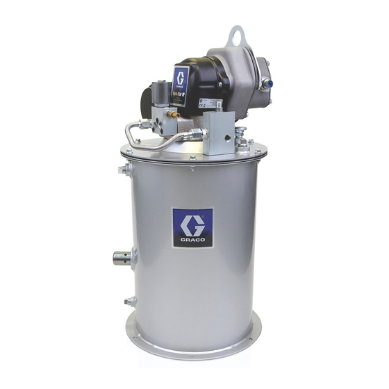
Page 2: Description
This system was designed for use on mobile mining equipment, spe- cifically haul trucks. At the heart of this system is the Graco Fireball pump, the most durable pump in the industry. The pump provides the lubricant pressure needed to activate the automatic lubrication system. - Page 3 Notes 309015...
- Page 4 Description (cont.) Controller Capabilities Low Reservoir Level Switch User must provide. Pump Power Supply Pressure Switch For System Control (air or hydraulic; air power is shown) Remote Alarm Device (Light or Horn) User must provide. KEY Fig. 1 Pump power supply Regulator Solenoid valve Pump module...
- Page 5 Description (cont.) Typical Installation The installation shown in Fig. 2 is only a guide for selecting and installing system components. Contact your Graco distributor for assistance in planning a system to suit your needs. Controller Capabilities Low Reservoir Level Switch...
-
Page 6: Product Warnings And Cautions
D This equipment is for professional use only. D Read all instruction manuals, tags, and labels before operating the equipment. D Use the equipment only for its intended purpose. If you are uncertain about usage, call your Graco distributor. D Do not alter or modify this equipment. Use only genuine Graco parts and accessories. - Page 7 Product Warnings and Cautions (cont.) WARNING SKIN INJECTION HAZARD Fluid from the dispensing valve, leaks or ruptured components can inject fluid into your body and cause extremely serious injury, including the need for amputation. Fluid splashed in the eyes or on the skin can also cause serious injury.
- Page 8 Product Warnings and Cautions (cont.) WARNING FIRE AND EXPLOSION HAZARD Improper grounding, poor ventilation, open flames or sparks can cause a hazardous condition and result in a fire or explosion and serious injury. D Ground the equipment and the object being dispensed to. See Grounding in your separate pump manual.
-
Page 9: Automatic Lube Definitions
Automatic Lubrication Definitions Definitions “Pump on” time The duration that the pump has power supplied to it. This is controlled by the timer. All injectors must fully dis- pense within this time frame in a properly designed system. “Pause interval” time The duration between automatic lubrication cycles. -
Page 10: System Components
System Components 1. Controls Timer 8852A The timer is the “brain” of the automatic lube system. It requires a constant 24 volt power supply. Its function is to supply and remove power from the pump module via a solenoid valve, at predetermined time intervals. The timer must be programmed for “pump on”... - Page 11 System Components (cont.) 2. Pump Module Model 241573 Model 247444 Model 247574 50:1 FireBall 10:1 Dynastar 10:1 Dynastar Model 243159 5:1 Dynastar Pump The pump provides the necessary lubricant pressure needed to operate the injectors. Vent valve 9037A The vent valve relieves the lubricant pressure back to the reservoir at the end of each lubrication cycle. Pressure relief 9037A The pressure relief valve is a safety item to prevent over-pressurization of the system.
- Page 12 System Components (cont.) 3. Injectors Injectors The function of the injector is to measure a preset amount of lubricant for dispense into bearing points for each au- tomatic lubrication cycle. Injector outputs can be combined for a common bearing point with a large grease require- ment but the output for a single injector can not be split into multiple bearing points.
- Page 13 System Components (cont.) 4. Lubricant Graco suggests the use of the following lubricant grades for the given temperature ranges. NLGI #1 ( 0_ F to +130_ F) NLGI #0 (–40_ F to +30_ F) 5. Distribution Lines Main supply line Line that supplies lubricant from the pump module to the injector groups or banks.
-
Page 14: Automatic Lubrication System Design Guide
Automatic Lubrication System Design Guide System Design Outlined below is a simple five step method for designing a single line parallel automatic lubrication system for a haul truck. Step 1: Identify points for lubrication Step 2: Determine grease volume requirement for each bearing size Step 3: Determine number of injectors per point, injector setting and timer setting Step 4: Determine supply line and feed line plumbing requirements Step 5: Determine bill of material... - Page 15 Automatic Lubrication System Design Guide SYSTEM WORKSHEET Fill out the worksheet below. Use the appropriate Bearing Lubricant Volume Chart (page 16) to determine the bearing lubricant volume. Use the Injector and Timer Setting Chart (page 17) to fill out the injector settings and timer settings. Lube Description Journal...
- Page 16 Automatic Lubrication System Design Guide JOURNAL BEARING LUBRICANT VOLUME CHART NOTE: Tabulated values are in cubic in. (in.#) TI0088A L = Length (in.) Dia. (in.) 0.01 0.01 0.02 0.03 0.03 0.04 0.04 0.05 0.06 0.06 0.07 0.08 0.08 0.09 0.09 0.10 0.11 0.11...
- Page 17 Automatic Lubrication System Design Guide INJECTOR AND TIMER SETTING CHART NOTE: Place a check mark for each lube point in the appropriate bearing volume column. Lube Point Bearing Volume (cu. in.) 0.05 0.10 0.15 0.20 0.25 0.30 0.35 0.40 0.45 0.50 0.55 0.60...
- Page 18 Automatic Lubrication System Design Guide Step 4: Determine supply line and feed line plumbing requirements When connecting the supply line to several groups of injectors, use a branch supply line that comes off the main supply line to prevent having to vent through a number of injector manifolds. Use the same size lines for the main supply line and branch supply lines with these systems.
-
Page 19: System Installation
Install in power supply line to pump module. Connect leads to timer output. Do not ground leads on Graco timer 115123 (refer to manual 308950). Connect either lead to the + output on timer and the other lead to the – output on timer. - Page 20 System Installation (cont.) Dimensions – Model 247574 Mounting Diagram Six 7/16 in. (11 mm) diameter holes on 13–7/8 in. (352 mm) bolt circle. Hydraulic high pressure inlet 3/8 in. nps swivel Overflow port 1/2 in. npt Hydraulic tank 3/4 in. nps swivel 35.15 in.
- Page 21 System Installation (cont.) Supply lines; 3500 psi (241 bar, 24 MPa) rating or better Install to vent valve outlet on pump module. Secure to framework to prevent abuse and abrasion. Use branch lines to connect to injector banks and groups. NOTE: Per JIC standards, copper tubing should not be used in lubricant systems.
-
Page 22: System Operation
System Operation System Operation Pump Module The pump module provides pressure and pressure relief function necessary for injector operation according to timer programming. 1. Fill and prime pump module reservoir per instruction manual 308955 for air-powered systems and manual 309098 for hydraulic-powered systems. 2. - Page 23 System Operation (cont.) Basic Injector Operation Refer to Fig. 3. Stage 1 At stage 1, the injector’s discharge chamber contains lubricant from the preceding cycle. This lubricant is not under pressure, and the piston is at rest. As the next cycle begins, pressurized lubricant enters the injector and starts to open the slide valve, which com- presses the injector spring.
-
Page 24: Troubleshooting
Troubleshooting Problem Cause Solution System does not build sufficient Pump malfunction Refer to pump manual 308955 or pressure 309098 Pump turned off too soon Increase timer “pump on” setting Solenoid valve malfunction Repair or replace Too low or no power supply Turn power supply pressure up or supply on Vent valve seal failure... - Page 25 Troubleshooting (cont.) Problem Cause Solution System does not vent properly Vent valve malfunction Repair or replace vent valve Injector malfunction Repair or replace injector Too many injectors on branch line Reconfigure branch line to correct Supply line too small Install supply line with larger diameter Grease too viscous Use lighter grease, NLGI #0 or lighter for cold temperatures...
-
Page 26: Graco Phone Number
Graco Information TO PLACE AN ORDER, contact your Graco distributor or call to identify the nearest distributor: Phone 612–623–6928, or Toll Free 1–800–533–9655 Fax: 612–378–3590 All written and visual data contained in this document reflect the latest product information available at the time of publication.
Need help?
Do you have a question about the 309015B and is the answer not in the manual?
Questions and answers