Table of Contents
Advertisement
Quick Links
Operation/Service/Parts
HP50 High Pressure
Lubricators
For dispensing non-corrosive and non-abrasive oils and synthetic-based lubricants.
Models: page 2
50,000 psi (344 MPa, 3,447 bar) Maximum Working Pressure
Important Safety Instructions
Read all warnings and instructions in this
manual. Save these instructions.
311842G
Bulletin 40240/51030
EN
TI8512
ti13802
Advertisement
Table of Contents

Summary of Contents for Graco HP50
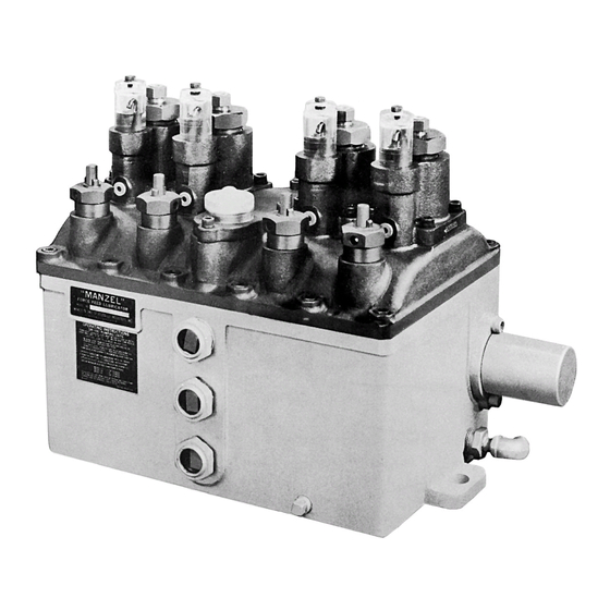
- Page 1 Operation/Service/Parts HP50 High Pressure 311842G Lubricators Bulletin 40240/51030 For dispensing non-corrosive and non-abrasive oils and synthetic-based lubricants. Models: page 2 50,000 psi (344 MPa, 3,447 bar) Maximum Working Pressure Important Safety Instructions Read all warnings and instructions in this manual. Save these instructions.
- Page 2 Models Models Model Description HP-50 Lubricator with 4 pumps and low level 258262 HP-50 Lubricator with 4 pumps, provision for flange mounted auto fill and low level 258263 in fill plate and proximity switch shaft rotations indicator on right HP-50 Lubricator with 4 pumps 562925†...
- Page 3 Warnings Warnings The following warnings are for the setup, use, grounding, maintenance, and repair of this equipment. The exclama- tion point symbol alerts you to a general warning and the hazard symbol refers to procedure-specific risk. Refer back to these warnings. Additional, product-specific warnings may be found throughout the body of this manual where applicable.
- Page 4 Warnings WARNING SKIN INJECTION HAZARD High-pressure fluid from dispense valve, hose leaks, or ruptured components will pierce skin. This may look like just a cut, but it is a serious injury that can result in amputation. Get immediate surgical treatment. •...
-
Page 5: Installation
Installation Installation Drive Mechanism NOTICE All installation, maintenance, and repair work must be completed by qualified personnel. A 1-1/4 inch diameter shaft is provided to connect the lubricator to a rotary power source. A woodruff key and Grounding key way on the shaft are provided to aid in connecting this source. - Page 6 Installation NOTE: 2. Remove the vent plug (A) on top of the sight glass and fill the housing sight well with oil to 3/8-inch • Three sight glasses (B) are provided in the res- below the discharge of the drip tube (F .
- Page 7 Installation Pumping Rate During the pump suction stroke an amount of oil equal to the pump displacement is drawn through the drip tube into the sight well. The amount of fluid in the site tube indicates the pumping rate. NOTE: Allow sufficient time to insure an accurate rate indication.
-
Page 8: Pressure Relief Procedure
Service Service Pressure Relief Procedure Service Instructions 1. Check lubricator operation by observing the drip tube. If the sight glass well pumps dry or no flow is observed, check the following points until the cause is determined and corrected. The equipment stays pressurized until pressure is •... - Page 9 Service 2. If items listed in step 1 are not the cause, check the NOTE: pump assembly. The following items should be • Keep a spare pump on hand for use during checked before removing the pump assembly from emergencies and when the pump is being the cover.
- Page 10 Service • If the sight glass continues to fill with lubricant: • When the unit is operating the sight level will vary depending on temperature variations. a. Check all terminal check valves for proper a. If the level falls to less than 1/4 inch above operation.
- Page 11 High Pressure Lubricator Parts High Pressure Lubricator Parts Part No. Description Part No. Description 556836 LABEL, operating instructions 556340 BEARING, ecc shaft 556872 LABEL, identification 556343 BEARING, slv, bronze 557062 SHAFT, crank 560148 BUSHING, reservoir 15M340 RESERVOIR 560157 NUT, fluid adjustment 560398 COVER, reservoir 560169 PIN, lever 560483 LEVER, shoe...
-
Page 12: Pump Parts
High Pressure Lubricator Parts Part No. Description 557171 COVER, oil hole 557391 PLUG, dryseal, 1/4 nptf 555451 PLUG, pipe 556517 SCREW, socket head 3/8 x 15 x 0.875 555424 PIN, 0.312 Diameter groove type Pump Parts Part No. Description 560162 NUT 560172 PIN, collar 555564 RING, retainer 560195 RING, retaining spring... - Page 13 High Pressure Lubricator Parts Check Valve Parts Drawing and Parts List 564335 - Discharge check valve 564336 - Terminal check valve *Supplied with Discharge Check Valve 564335 only. Not supplied with Terminal Check Valves. 564335 Discharge Check Valve - 3/8” OD Tube 564336 Terminal Check Valve Ref.
-
Page 14: Technical Data
Technical Data Technical Data Plunger Diameter 1/4 in. (0.64 cm) HP-50 Maximum Operating Pressure 50,000 psi (344 MPa, 3,447 bar) Reservoir Capacity 9 quarts (8.5 liters) from centerline of top gauge glass to centerline of bottom gauge glass Maximum Pumping Rate based on SAE 40 oil — (approx. 4 drops) 0.008 in (0.133 cc) per stroke Minimum Pump Rate 0.001 in... - Page 15 Dimensions Dimensions 2.75 in. 11.75 in. (6.98 cm) (29.84 cm) 3.125 in. 7.93 cm) 14.765 in. (37.5 cm) 7.68 in (19. 5 cm) 4.125 in. (10.4 cm) 16.625 in. (42.22 cm) 13.5 in. (34.29 cm) TI8514 11.56 in (29.36 cm) 311842G...
-
Page 16: Graco Standard Warranty
With the exception of any special, extended, or limited warranty published by Graco, Graco will, for a period of twelve months from the date of sale, repair or replace any part of the equipment determined by Graco to be defective.


Need help?
Do you have a question about the HP50 and is the answer not in the manual?
Questions and answers