Table of Contents
Advertisement
Quick Links
GETTING STARTED GUIDE
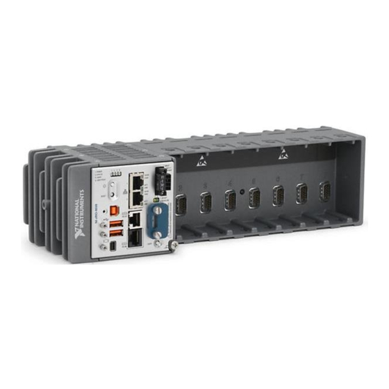
NI cRIO-9036
Embedded CompactRIO Controller with Real-Time Processor and
Reconfigurable FPGA
This document describes how to begin using the National Instruments cRIO-9036.
Safety Guidelines
Caution
Product misuse can result in a hazard. You can compromise the safety protection
built into the product if the product is damaged in any way. If the product is
damaged, return it to NI for repair.
Do not operate the cRIO-9036 in a manner not specified in this document.
Advertisement
Table of Contents

Related Manuals for National Instruments cRIO-9036


Summary of Contents for National Instruments cRIO-9036
- Page 1 Safety Guidelines Caution Do not operate the cRIO-9036 in a manner not specified in this document. Product misuse can result in a hazard. You can compromise the safety protection built into the product if the product is damaged in any way. If the product is...
-
Page 2: Safety Guidelines For Hazardous Locations
Safety Guidelines for Hazardous Locations The cRIO-9036 is suitable for use in Class I, Division 2, Groups A, B, C, D, T4 hazardous locations; Class I, Zone 2, AEx nA IIC T4 and Ex nA IIC T4 hazardous locations; and nonhazardous locations only. -
Page 3: Electromagnetic Compatibility Guidelines
30 m (100 ft). The length of any cable connected to the USB host ports must be no longer than 5 m (16 ft). Caution The USB device port is intended only for use in device configuration, application deployment, debug, and maintenance. NI cRIO-9036 Getting Started Guide | © National Instruments | 3... -
Page 4: Special Conditions For Marine Applications
In addition, take precautions when designing, selecting, and installing measurement probes and cables to ensure that the desired EMC performance is attained. Preparing the Environment Ensure that the environment in which you are using the cRIO-9036 meets the following specifications. Operating temperature -40 °C to 70 °C... -
Page 5: Verifying The Kit Contents
2. USB A-to-B Cable 3. Ferrite (x2) Installing Software on the Host Computer Before using the cRIO-9036, you must install the following application software and device drivers on the host computer in this order: LabVIEW 2014 SP1 or later LabVIEW Real-Time Module 2014 SP1 or later... -
Page 6: Installing C Series Modules
Complete the following steps to install a C Series module. Verify that power is not connected to the I/O connector(s) on the C Series module. If the system is in a nonhazardous location, the cRIO-9036 can be powered on when you install modules. - Page 7 6. Ground Screw 13. USB Device Port 7. USER1 Button 14. Power and Reset Buttons Connecting the cRIO-9036 to Ground You must connect the cRIO-9036 grounding terminal to the grounding electrode system of the facility. What to Use • Ring lug •...
- Page 8 C Series modules. The cRIO-9036 has a primary power input, V1, and a secondary power input, V2. The POWER LED on the cRIO-9036 indicates which power input is in use, as shown in the following table.
- Page 9 (24 VDC, 5 A, 100 VAC to 120 VAC/200 VAC to 240 VAC input) What to Do Complete the following steps to connect a power supply to the cRIO-9036. Ensure that your power supply is powered off. Install the ferrite on the negative and positive leads of the power supply, as shown in the following figure.
- Page 10 Power on the primary power supply and optional secondary power supply. Powering On the cRIO-9036 When you power on the cRIO-9036 for the first time, the device boots into safe mode. The POWER LED illuminates, the STATUS LED illuminates briefly, and then the STATUS LED blinks twice every few seconds.
-
Page 11: Setting A System Password
The device driver software automatically detects the cRIO-9036. If the device driver software does not detect the cRIO-9036, verify that you installed the appropriate NI software in the correct order on the host computer. You can also use the Ethernet port to connect directly to the host computer or network. - Page 12 Click Next. Select NI Scan Engine from the software add-ons. Select any additional software to install. If you plan on using the cRIO-9036 with the LabVIEW FPGA Module, you can click Next. Click NI Scan Engine if you plan on using the cRIO-9036 without the LabVIEW FPGA Module.
-
Page 13: Verify The System Ip Configuration
Set a new DHCP connection by holding the RESET button down for 5 seconds. The STATUS LED repeats the same behavior from Step If the cRIO-9036 fails to set a new DHCP address, it assigns itself a link-local IP address. If the DHCP connection is successful and appropriate for your application, skip to Step In MAX, expand your system under Remote Systems. -
Page 14: System Reset
Ensure that UDP port 44525 is open to communication on the host computer. If you are using an intelligent switch on the network, ensure that it is not disabling UDP port 44525. System Reset The following figure shows the reset behavior of the cRIO-9036. Figure 5. Reset Button Behavior Press and hold RESET button for <... - Page 15 Remove any shorts and cycle power the cRIO-9036. If the problem persists, contact NI. — The cRIO-9036 is in run mode. Software is installed and the operating system is running. NI cRIO-9036 Getting Started Guide | © National Instruments | 15...
-
Page 16: Where To Go Next
(EMC) and product safety. You can obtain the DoC for your product by visiting ni.com/certification. If your product supports calibration, you can obtain the calibration certificate for your product at ni.com/calibration. 16 | ni.com | NI cRIO-9036 Getting Started Guide... - Page 17 United States, visit the Worldwide Offices section of ni.com/ niglobal to access the branch office websites, which provide up-to-date contact information, support phone numbers, email addresses, and current events. NI cRIO-9036 Getting Started Guide | © National Instruments | 17...
- Page 18 CONTAINED HEREIN AND SHALL NOT BE LIABLE FOR ANY ERRORS. U.S. Government Customers: The data contained in this manual was developed at private expense and is subject to the applicable limited rights and restricted data rights as set forth in FAR 52.227-14, DFAR 252.227-7014, and DFAR 252.227-7015. © 2015 National Instruments. All rights reserved. 375695D-01 Oct15...
Need help?
Do you have a question about the cRIO-9036 and is the answer not in the manual?
Questions and answers