Table of Contents
Advertisement
USER MANUAL
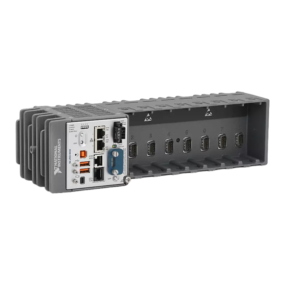
NI cRIO-9035
Embedded CompactRIO Controller with Real-Time Processor and
Reconfigurable FPGA
This document describes the features of the NI cRIO-9035 and NI cRIO-9035 Sync and
contains information about mounting and operating the device.
In this document, the NI cRIO-9035 and NI cRIO-9035 Sync are inclusively referred to as the
cRIO-9035.
For more information about timing and synchronization capabilities of NI cRIO-9035 Sync,
visit
ni.com/info
and enter the Info Code
RJ-45 Gigabit
Ethernet Port 1
RJ-45 Gigabit
Ethernet Port 2
USB 2.0
Host Port
USB 2.0
Host Port
USB 2.0
Device Port
cRIO-9035
cRIO9035sync
E3825 1.33 GHz Dual-Core
System-On-Chip
Watchdog
Kintex-7 FPGA
.
Intel Atom
+
+
Xilinx
7K70T
+
+
Mini
DisplayPort
1 GB DDR3L
4 GB SATA
Disk-On-Chip
RJ-50
RS-232
Serial Port
RJ-50
RS-485/422 (DTE)
Serial Port
SD Card
Slot
Hardware
Data
Advertisement
Table of Contents

Subscribe to Our Youtube Channel
Related Manuals for National Instruments CompactRIO cRIO-9035


Summary of Contents for National Instruments CompactRIO cRIO-9035
- Page 1 USER MANUAL NI cRIO-9035 Embedded CompactRIO Controller with Real-Time Processor and Reconfigurable FPGA This document describes the features of the NI cRIO-9035 and NI cRIO-9035 Sync and contains information about mounting and operating the device. In this document, the NI cRIO-9035 and NI cRIO-9035 Sync are inclusively referred to as the cRIO-9035.
-
Page 2: Table Of Contents
Contents Configuring the cRIO-9035...................... 2 Connecting the cRIO-9035 to the Host Computer or Network Using Ethernet....3 Configuring Startup Options..................... 4 cRIO-9035 Features........................6 Ports and Connectors......................6 Buttons..........................14 LEDs..........................16 Chassis Grounding Screw....................19 Internal Real-Time Clock....................20 CMOS Battery.........................20 File System........................20 Installing the Module Immobilization Accessory.............. -
Page 3: Connecting The Crio-9035 To The Host Computer Or Network Using Ethernet
Obtain IP settings from the host computer. Click Start»Control Panel»Network and Sharing Center. Select the primary network connection, which may appear as Local Area Connection or something similar. NI cRIO-9035 User Manual | © National Instruments | 3... -
Page 4: Configuring Startup Options
In the dialog box that appears, click Properties. Select Internet Protocol Version 4 (TCP/IPv4). Click Properties. Record the IP address, Subnet mask, and Default gateway address. You need these settings to configure the network settings of the cRIO-9035 and to restore the network settings of the host computer. - Page 5 You can also browse and edit files on the cRIO-9035 within a graphical working environment. For more information, refer to the Using the Embedded UI to Access RT Target VIs topic in the LabVIEW Help. NI cRIO-9035 User Manual | © National Instruments | 5...
-
Page 6: Crio-9035 Features
cRIO-9035 Features The cRIO-9035 provides the following features. Ports and Connectors The cRIO-9035 provides the following ports and connectors. Figure 1. cRIO-9035 Ports and Connectors 1. RJ-45 Gigabit Ethernet Ports 5. RS-485/422 (DTE) Serial Port 2. Power Connector 6. Mini DisplayPort 3. - Page 7 18 Power Connector The cRIO-9035 has a power connector to which you can connect a primary and secondary power supply. The following table shows the pinout for the power connector. NI cRIO-9035 User Manual | © National Instruments | 7...
- Page 8 Table 4. Power Connector Pinout Pinout Description Primary power input Common Secondary power input Common Caution The C terminals are internally connected to each other, but are not connected to chassis ground. This isolation is intended to prevent ground loops and does not meet UL ratings for safety isolation.
- Page 9 The RS-232 serial port cannot be accessed by the user application when the Console Out startup option is enabled. The following table shows the pinout for the RS-232 serial port. NI cRIO-9035 User Manual | © National Instruments | 9...
- Page 10 Table 7. RS-232 Serial Port Pinout Pinout Signal No Connect You can use the Ring Indicator (RI) on pin 2 to wake the controller from a low-power state. You can drive RI with a logic level high to wake the cRIO-9035. Refer to the specifications on ni.com/manuals for the RI wake voltage.
- Page 11 Caution Do not hot-swap Mini DisplayPort devices while the cRIO-9035 is in a hazardous location or connected to high voltages. The following table shows the pinout for the Mini DisplayPort. NI cRIO-9035 User Manual | © National Instruments | 11...
- Page 12 Table 11. Mini DisplayPort Pinout Signal Pinout Signal DP_PWR AUX_CH(n) ML_Lane2(n) AUX_CH(p) ML_Lane2(p) ML_Lane3(n) ML_Lane1(n) ML_Lane3(p) ML_Lane1(p) CONFIG2 ML_Lane0(n) CONFIG1 ML_Lane0(p) Hot Plug The following adapters are available to connect the Mini DisplayPort to full-size DisplayPort, VGA, or DVI. The cRIO-9035 only supports DVI single link. Refer to the cRIO-9035 pricing page on ni.com for a complete list of cables and accessories.
- Page 13 Ferrite (711849-01), included with the cRIO-9035 • USB cables What to Do Install the ferrite on the USB cables, as shown in the following figure. Figure 2. Installing a Ferrite on the USB Cables NI cRIO-9035 User Manual | © National Instruments | 13...
-
Page 14: Buttons
Pass the cables through the ferrite, leaving 50 mm to 75 mm (2 in. to 3 in.) between the ferrite and the end of the cables. The ferrite can accommodate up to two USB cables depending on the diameter of each cable. Close the ferrite around the cables. - Page 15 Press and hold RESET button for < 5 s • Network settings reset Safe Mode • RT Startup App disabled • FPGA Startup App disabled Press and hold RESET button for ≥ 5 s NI cRIO-9035 User Manual | © National Instruments | 15...
-
Page 16: Leds
USER1 Button The cRIO-9035 has a general-purpose USER1 button that is user-defined. You can read the state of the USER1 button from your LabVIEW FPGA application. CMOS Reset Button The cRIO-9035 has a CMOS reset button that you can use to reset the CMOS and the BIOS. LEDs The cRIO-9035 provides the following LEDs. - Page 17 Remove any shorts and cycle power the cRIO-9035. If the problem persists, contact NI. — The cRIO-9035 is in run mode. Software is installed and the operating system is running. NI cRIO-9035 User Manual | © National Instruments | 17...
- Page 18 User LEDs You can define the USER1 and USER FPGA1 LEDs to meet the needs of your application. The following table lists the USER1 and USER FPGA1 LED indicators. Table 18. User LEDs LED Color Description USER1 Green/Yellow Use LabVIEW Real-Time to define the USER1 LED with the RT LEDs VI.
-
Page 19: Chassis Grounding Screw
1.31 mm (16 AWG) or larger wire. Attach a ring lug to the wire and attach the wire NI cRIO-9035 User Manual | © National Instruments | 19... -
Page 20: Internal Real-Time Clock
to the chassis grounding terminal. Solder the other end of the wire to the cable shield. Use shorter wire for better EMC performance. For more information about ground connections, visit ni.com/info and enter the Info Code emcground Internal Real-Time Clock The cRIO-9035 contains an internal real-time clock that maintains system time when the cRIO-9035 is powered off. -
Page 21: Installing The Module Immobilization Accessory
Torx T10 and T20. The other set is a tamper-resistant set of screws that require a security driver type, Torx T10H and T20H. Use the tamper-resistant set to help prevent unintended modification of the system. NI cRIO-9035 User Manual | © National Instruments | 21... -
Page 22: Module Immobilization Accessory Dimensions
Ensure that all the C Series modules are installed in the cRIO-9035 and the latches are locked in place. Remove the center right panel screw from the top and bottom of the cRIO-9035 using the Torx T10 driver. Slide the bracket into place, aligning the three clearance screw holes. Install the M4 x 0.7 button-head screw in the right end of the cRIO-9035 using the appropriate Torx T20 driver. -
Page 23: Mounting The Device
Before using any of these mounting methods, record the serial number from the back of the cRIO-9035 so that you can identify the cRIO-9035 in MAX. You will be unable to read the serial number after you mount the cRIO-9035. NI cRIO-9035 User Manual | © National Instruments | 23... -
Page 24: Dimensions
Dimensions The following figures show the front and side dimensions of the cRIO-9035. For detailed dimensional drawings and 3D models, visit ni.com/dimensions and search for the module number. Figure 9. cRIO-9035 Front Dimensions 328.8 mm (12.95 in.) 107.0 mm (4.21 in.) 107.0 mm (4.21 in.) 88.1 mm (3.47 in.) -
Page 25: Ambient Temperature
Measure the ambient temperature at each side of the cRIO-9035, 63.5 mm (2.50 in.) from the side and 38.1 mm (1.50 in.) forward from the rear of the cRIO-9035, as shown in the following figure. NI cRIO-9035 User Manual | © National Instruments | 25... -
Page 26: Mounting The Device Directly On A Flat Surface
Figure 13. cRIO-9035 Ambient Temperature Location 63.5 mm 63.5 mm (2.50 in.) (2.50 in.) 38.1 mm 38.1 mm 63.5 mm 63.5 mm (1.50 in.) (1.50 in.) (2.50 in.) (2.50 in.) 1. Location for measuring the ambient temperature Mounting the Device Directly on a Flat Surface For environments with high shock and vibration, NI recommends mounting the cRIO-9035 directly on a flat, rigid surface using the mounting holes in the cRIO-9035. - Page 27 120 mm (4.72 in.) 3× 20.3 mm (0.80 in.) 3× 20.3 mm (0.80 in.) 3× 23.7 mm (0.94 in.) 9× ISO M4 × 0.7 Thread 8 mm Maximum Insertion Depth NI cRIO-9035 User Manual | © National Instruments | 27...
-
Page 28: Mounting The Crio-9035 On A Panel
Mounting the cRIO-9035 on a Panel You can use the NI panel mounting kit to mount the cRIO-9035 on a panel. What to Use • cRIO-9035 • Screwdriver, Phillips #2 • NI panel mounting kit, 157267-01 – Panel mounting plate –... -
Page 29: Mounting The Crio-9035 On A Din Rail
NI DIN rail mounting kit, 157268-01 – DIN rail clip – M4 × 10 screws (x3) What to Do Complete the following steps to mount the cRIO-9035 on a DIN rail. NI cRIO-9035 User Manual | © National Instruments | 29... - Page 30 Align the cRIO-9035 and the DIN rail clip. Fasten the DIN rail kit to the cRIO-9035 using the screwdriver and M4 × 10 screws. Tighten the screws to a maximum torque of 1.3 N · m (11.5 lb · in.). You must use the screws provided with the NI DIN rail kit because they are the correct depth and thread for the DIN rail clip.
-
Page 31: Mounting The Device On A Rack
• Screwdriver, Phillips #2 • NI desktop mounting kit, 779473-01 – Desktop mounting brackets (x2) What to Do Complete the following steps to mount the cRIO-9035 on a desktop. NI cRIO-9035 User Manual | © National Instruments | 31... -
Page 32: Bios Configuration
Align the brackets with the mounting holes on the ends of the cRIO-9035. Use the screwdriver to tighten the captive screws on the end of the brackets. Desktop Mounting Dimensions The following figures show the desktop mounting dimensions for the cRIO-9035. Figure 16. -
Page 33: Power-On Self Test Warning Messages
The Main setup menu is displayed when you first enter the BIOS setup utility. BIOS Setup Utility Keyboard Navigation Use the following keys to navigate through the BIOS setup utility: NI cRIO-9035 User Manual | © National Instruments | 33... -
Page 34: Main Setup Menu
Table 21. Navigation Keys Key(s) Function(s) Left Arrow, Right Move between the different setup menus. If you are in a submenu, Arrow these keys have no effect, and you must press <Esc> to leave the submenu first. Up Arrow, Down Move between the options within a setup menu. -
Page 35: Advanced Setup Menu
SATA Controller(s)—This setting specifies whether the onboard SATA controller is enabled or disabled. The default value is Enabled. • Onboard Storage—This item displays the onboard drive detected in the system. NI cRIO-9035 User Manual | © National Instruments | 35... -
Page 36: Boot Setup Menu
USB Configuration Submenu The USB configuration submenu contains the USB host ports settings. The factory default settings provide the most compatible and optimal configuration. • USB Devices—This item lists the total number of devices detected in the system, categorized by device type. •... - Page 37 Floppy Drive BBS Priorities Submenu The Floppy Drive BBS Priorities submenu specifies the boot priority of floppy drive devices. NI cRIO-9035 User Manual | © National Instruments | 37...
-
Page 38: Save & Exit Menu
Boot Option #1, Boot Option #2, Boot Option #3—These settings specify that the main Boot Option Priorities list displays the highest priority device. Optionally, each device can be disabled if the device is not used as a boot device. Network Device BBS Priorities Submenu The Network Device BBS Priorities submenu specifies the boot priority of network devices. -
Page 39: Worldwide Support And Services
United States, visit the Worldwide Offices section of ni.com/ niglobal to access the branch office websites, which provide up-to-date contact information, support phone numbers, email addresses, and current events. NI cRIO-9035 User Manual | © National Instruments | 39... - Page 40 NI trademarks. Other product and company names mentioned herein are trademarks or trade names of their respective companies. For patents covering NI products/technology, refer to the appropriate location: Help»Patents in your software, the file on your media, or the National Instruments Patent Notice at . You can find patents.txt ni.com/patents...
Need help?
Do you have a question about the CompactRIO cRIO-9035 and is the answer not in the manual?
Questions and answers