Table of Contents
Advertisement
Quick Links
USER MANUAL
NI cRIO-9036
Embedded CompactRIO Controller with Real-Time Processor and
Reconfigurable FPGA
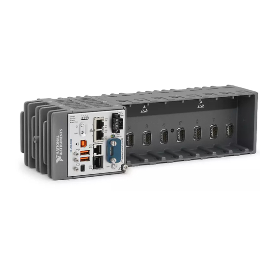
This document describes the features of the National Instruments cRIO-9036 and contains
information about mounting and operating the device.
RJ-45 Gigabit
Ethernet Port 1
RJ-45 Gigabit
Ethernet Port 2
USB 2.0
Host Port
USB 2.0
Host Port
USB 2.0
Device Port
cRIO-9036
E3825 1.33 GHz Dual-Core
System-On-Chip
Watchdog
Intel Atom
+
+
Xilinx
Kintex-7 FPGA
7K70T
+
+
Mini
DisplayPort
1 GB DDR3L
4 GB SATA
Disk-On-Chip
RJ-50
RS-232
Serial Port
RJ-50
RS-485/422 (DTE)
Serial Port
SD Card
Slot
Hardware
Data
Advertisement
Table of Contents

Related Manuals for National Instruments NI cRIO-9036


Summary of Contents for National Instruments NI cRIO-9036
- Page 1 USER MANUAL NI cRIO-9036 Embedded CompactRIO Controller with Real-Time Processor and Reconfigurable FPGA This document describes the features of the National Instruments cRIO-9036 and contains information about mounting and operating the device. RJ-45 Gigabit Intel Atom Mini Ethernet Port 1 DisplayPort E3825 1.33 GHz Dual-Core...
-
Page 2: Table Of Contents
Refer to the getting started guide on ni.com/manuals for basic configuration instructions and information about connecting to a host computer using the USB device port. NI recommends using the USB device port for configuration, debug, and maintenance. 2 | ni.com | NI cRIO-9036 User Manual... -
Page 3: Connecting The Crio-9036 To The Host Computer Or Network Using Ethernet
Obtain IP settings from the host computer. Click Start»Control Panel»Network and Sharing Center. Select the primary network connection, which may appear as Local Area Connection or something similar. NI cRIO-9036 User Manual | © National Instruments | 3... -
Page 4: Configuring Startup Options
Complete the following steps to configure the cRIO-9036 startup options in MAX. In MAX, expand your system under Remote Systems. Select the Startup Settings tab to configure the startup settings. cRIO-9036 Startup Options You can configure the following cRIO-9036 startup options. 4 | ni.com | NI cRIO-9036 User Manual... - Page 5 You can also browse and edit files on the cRIO-9036 within a graphical working environment. For more information, refer to the Using the Embedded UI to Access RT Target VIs topic in the LabVIEW Help. NI cRIO-9036 User Manual | © National Instruments | 5...
-
Page 6: Crio-9036 Features
The cRIO-9036 has two tri-speed RJ-45 Gigabit Ethernet ports. By default, both Ethernet ports are enabled and configured to obtain an IP address automatically. The Ethernet ports can be configured in MAX. The following table shows the pinout for the RJ-45 Gigabit Ethernet ports. 6 | ni.com | NI cRIO-9036 User Manual... - Page 7 18 Power Connector The cRIO-9036 has a power connector to which you can connect a primary and secondary power supply. The following table shows the pinout for the power connector. NI cRIO-9036 User Manual | © National Instruments | 7...
- Page 8 NI 9979 Strain Relief for 4-Position Power Connector 196939-01 Related Information POWER LED Indicators on page 16 SD Card Removable Storage The cRIO-9036 provides an SD card slot that can read from and write to NI-approved SD cards. 8 | ni.com | NI cRIO-9036 User Manual...
- Page 9 The RS-232 serial port cannot be accessed by the user application when the Console Out startup option is enabled. The following table shows the pinout for the RS-232 serial port. NI cRIO-9036 User Manual | © National Instruments | 9...
- Page 10 Find examples on how to use NI-Serial or NI-VISA to perform serial communication in the NI Example Finder. The NI Example Finder is located on the Help menu in the LabVIEW Help. The following table shows the pinout for the RS-485/422 (DTE) serial port. 10 | ni.com | NI cRIO-9036 User Manual...
- Page 11 Caution Do not hot-swap Mini DisplayPort devices while the cRIO-9036 is in a hazardous location or connected to high voltages. The following table shows the pinout for the Mini DisplayPort. NI cRIO-9036 User Manual | © National Instruments | 11...
- Page 12 If the cRIO-9036 is not in a hazardous location, you can connect and disconnect USB devices without affecting operation. The following table shows the pinout for the USB host ports. 12 | ni.com | NI cRIO-9036 User Manual...
- Page 13 Ferrite (711849-01), included with the cRIO-9036 • USB cables What to Do Install the ferrite on the USB cables, as shown in the following figure. Figure 2. Installing a Ferrite on the USB Cables NI cRIO-9036 User Manual | © National Instruments | 13...
-
Page 14: Buttons
Length Part Number NI Locking USB Cable 157788-01 Buttons The cRIO-9036 provides the following buttons. Figure 3. cRIO-9036 Buttons 1. Power Button 3. USER1 Button 2. RESET Button 4. CMOS Reset Button 14 | ni.com | NI cRIO-9036 User Manual... - Page 15 Press and hold RESET button for < 5 s • Network settings reset Safe Mode • RT Startup App disabled • FPGA Startup App disabled Press and hold RESET button for ≥ 5 s NI cRIO-9036 User Manual | © National Instruments | 15...
-
Page 16: Leds
Table 16. POWER LED Indicators LED Color LED Pattern Indication Green Solid The cRIO-9036 is powered from the V1 input. Yellow Solid The cRIO-9036 is powered from the V2 input. — The cRIO-9036 is powered off. 16 | ni.com | NI cRIO-9036 User Manual... - Page 17 Remove any shorts and cycle power the cRIO-9036. If the problem persists, contact NI. — The cRIO-9036 is in run mode. Software is installed and the operating system is running. NI cRIO-9036 User Manual | © National Instruments | 17...
- Page 18 100 Mbit/s data rate selected — 10 Mbit/s data rate selected SD LED Indicators The cRIO-9036 has two LEDs that indicate the SD card drive mount status and activity. The following table lists SD LED indicators. 18 | ni.com | NI cRIO-9036 User Manual...
-
Page 19: Chassis Grounding Screw
1.31 mm (16 AWG) or larger wire. Attach a ring lug to the wire and attach the wire NI cRIO-9036 User Manual | © National Instruments | 19... -
Page 20: Internal Real-Time Clock
For example, it is possible to link , where /C/ni-rt/system dynamic libraries are deployed on other LabVIEW Real-Time targets, to /usr/local/lib where they are stored on the cRIO-9036, if the application requires this. 20 | ni.com | NI cRIO-9036 User Manual... -
Page 21: Installing The Module Immobilization Accessory
Torx T10 and T20. The other set is a tamper-resistant set of screws that require a security driver type, Torx T10H and T20H. Use the tamper-resistant set to help prevent unintended modification of the system. NI cRIO-9036 User Manual | © National Instruments | 21... -
Page 22: Module Immobilization Accessory Dimensions
NI recommends using a liquid thread locker for all fasteners if the system is expected to experience vibration for an extended amount or time. Module Immobilization Accessory Dimensions The following figure shows the Module Immobilization accessory dimensions for the cRIO-9036. 22 | ni.com | NI cRIO-9036 User Manual... -
Page 23: Mounting The Device
Before using any of these mounting methods, record the serial number from the back of the cRIO-9036 so that you can identify the cRIO-9036 in MAX. You will be unable to read the serial number after you mount the cRIO-9036. NI cRIO-9036 User Manual | © National Instruments | 23... -
Page 24: Dimensions
Your installation must meet the following requirements for cooling and cabling clearance. Allow 25.4 mm (1.00 in.) on the top and the bottom of the cRIO-9036 for air circulation, as shown in the following figure. 24 | ni.com | NI cRIO-9036 User Manual... -
Page 25: Ambient Temperature
Measure the ambient temperature at each side of the cRIO-9036, 63.5 mm (2.50 in.) from the side and 38.1 mm (1.50 in.) forward from the rear of the cRIO-9036, as shown in the following figure. NI cRIO-9036 User Manual | © National Instruments | 25... -
Page 26: Mounting The Device Directly On A Flat Surface
M4 screw (x6), user provided, which must not exceed 8 mm of insertion into the cRIO-9036 What to Do Complete the following steps to mount the cRIO-9036 directly on a flat surface. 26 | ni.com | NI cRIO-9036 User Manual... - Page 27 120 mm (4.72 in.) 3× 20.3 mm (0.80 in.) 3× 20.3 mm (0.80 in.) 3× 23.7 mm (0.94 in.) 9× ISO M4 × 0.7 Thread 8 mm Maximum Insertion Depth NI cRIO-9036 User Manual | © National Instruments | 27...
-
Page 28: Mounting The Crio-9036 On A Panel
Fasten the panel mounting plate to the surface using the screwdriver and screws that are appropriate for the surface. The maximum screw size is M5 or number 10. Panel Mounting Dimensions The following figure shows the panel mounting dimensions for the cRIO-9036. 28 | ni.com | NI cRIO-9036 User Manual... -
Page 29: Mounting The Crio-9036 On A Din Rail
NI DIN rail mounting kit, 157268-01 – DIN rail clip – M4 × 10 screws (x3) What to Do Complete the following steps to mount the cRIO-9036 on a DIN rail. NI cRIO-9036 User Manual | © National Instruments | 29... - Page 30 Press down firmly to compress the spring until the clip locks in place on the DIN rail. Caution Ensure that no C Series modules are in the cRIO-9036 before removing it from the DIN rail. 30 | ni.com | NI cRIO-9036 User Manual...
-
Page 31: Mounting The Device On A Rack
• Screwdriver, Phillips #2 • NI desktop mounting kit, 779473-01 – Desktop mounting brackets (x2) What to Do Complete the following steps to mount the cRIO-9036 on a desktop. NI cRIO-9036 User Manual | © National Instruments | 31... -
Page 32: Bios Configuration
The cRIO-9036 BIOS configuration information is stored in a nonvolatile memory location that does not require a battery to preserve the settings. Additionally, the BIOS optimizes boot time by saving specific system information to memory backed up by a battery (CMOS). 32 | ni.com | NI cRIO-9036 User Manual... -
Page 33: Power-On Self Test Warning Messages
The Main setup menu is displayed when you first enter the BIOS setup utility. BIOS Setup Utility Keyboard Navigation Use the following keys to navigate through the BIOS setup utility: NI cRIO-9036 User Manual | © National Instruments | 33... -
Page 34: Main Setup Menu
System Time—This setting controls the time of day, which is stored in a battery-backed real-time clock. Most operating systems also include a way to change this setting. Use <+> and <-> in conjunction with <Enter> and <Tab> to change these values. 34 | ni.com | NI cRIO-9036 User Manual... -
Page 35: Advanced Setup Menu
SATA Controller(s)—This setting specifies whether the onboard SATA controller is enabled or disabled. The default value is Enabled. • Onboard Storage—This item displays the onboard drive detected in the system. NI cRIO-9036 User Manual | © National Instruments | 35... -
Page 36: Boot Setup Menu
Priorities menu. The system must be restarted for this setting to take effect. The default value is Disabled. • Boot Option Priorities—These settings specify the order in which the BIOS checks for bootable devices, including the local hard disk drive, removable devices such as USB 36 | ni.com | NI cRIO-9036 User Manual... - Page 37 Floppy Drive BBS Priorities Submenu The Floppy Drive BBS Priorities submenu specifies the boot priority of floppy drive devices. NI cRIO-9036 User Manual | © National Instruments | 37...
-
Page 38: Save & Exit Menu
BIOS setup options, the system will continue booting to the selected device without first rebooting. If BIOS setup options have been changed and saved, a reboot will be required and the boot override selection will not be valid. 38 | ni.com | NI cRIO-9036 User Manual... -
Page 39: Worldwide Support And Services
United States, visit the Worldwide Offices section of ni.com/ niglobal to access the branch office websites, which provide up-to-date contact information, support phone numbers, email addresses, and current events. NI cRIO-9036 User Manual | © National Instruments | 39... - Page 40 NI trademarks. Other product and company names mentioned herein are trademarks or trade names of their respective companies. For patents covering NI products/technology, refer to the appropriate location: Help»Patents in your software, the file on your media, or the National Instruments Patent Notice at . You can find patents.txt ni.com/patents...
Need help?
Do you have a question about the NI cRIO-9036 and is the answer not in the manual?
Questions and answers