
Related Manuals for National Instruments cRIO-9037


Summary of Contents for National Instruments cRIO-9037
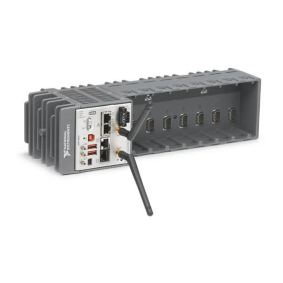
- Page 1 GETTING STARTED GUIDE NI cRIO-9037 Embedded CompactRIO Controller with Real-Time Processor and Reconfigurable FPGA This document describes how to begin using the National Instruments cRIO-9037.
-
Page 2: Safety Guidelines For Hazardous Locations
Safety Guidelines for Hazardous Locations The cRIO-9037 is suitable for use in Class I, Division 2, Groups A, B, C, D, T4 hazardous locations; Class I, Zone 2, AEx nA IIC T4 Gc and Ex nA IIC T4 Gc hazardous locations; and nonhazardous locations only. -
Page 3: Special Conditions For Hazardous Locations Use In Europe And Internationally
Special Conditions for Hazardous Locations Use in Europe and Internationally The cRIO-9037 has been evaluated as Ex nA IIC T4 Gc equipment under DEMKO 12 ATEX 1202658X and is IECEx UL 14.0089X certified. Each device is marked II 3G and is suitable for use in Zone 2 hazardous locations, in ambient temperatures of -20 °C ≤... -
Page 4: Special Conditions For Marine Applications
In addition, take precautions when designing, selecting, and installing measurement probes and cables to ensure that the desired EMC performance is attained. Preparing the Environment Ensure that the environment in which you are using the cRIO-9037 meets the following specifications. Operating temperature -20 °C to 55 °C... -
Page 5: Unpacking The Kit
Store the device in the antistatic package when the device is not in use. Verifying the Kit Contents Verify that the following items are included in the cRIO-9037 kit. Figure 1. cRIO-9037 Kit Contents 1. cRIO Device with Power Connector 4. -
Page 6: Installing Software On The Host Computer
Complete the following steps to install a C Series module. Verify that power is not connected to the I/O connector(s) on the C Series module. If the system is in a nonhazardous location, the cRIO-9037 can be powered on when you install modules. -
Page 7: Removing C Series Modules
Verify that power is not connected to the I/O connector(s) on the C Series module before you remove a module from the cRIO-9037. If the system is in a nonhazardous location, the cRIO-9037 can be powered on when you remove modules. - Page 8 6. Ground Screw 13. USB Device Port 7. WLAN LED 14. Power and Reset Buttons Connecting the cRIO-9037 to Ground You must connect the cRIO-9037 grounding terminal to the grounding electrode system of the facility. What to Use • Ring lug •...
- Page 9 C Series modules. The cRIO-9037 has a primary power input, V1, and a secondary power input, V2. The POWER LED on the cRIO-9037 indicates which power input is in use, as shown in the following table.
- Page 10 (24 VDC, 5 A, 100 VAC to 120 VAC/200 VAC to 240 VAC input) What to Do Complete the following steps to connect a power supply to the cRIO-9037. Ensure that your power supply is powered off. Install the ferrite on the negative and positive leads of the power supply, as shown in the following figure.
- Page 11 Power on the primary power supply and optional secondary power supply. Powering On the cRIO-9037 When you power on the cRIO-9037 for the first time, the device boots into safe mode. The POWER LED illuminates, the STATUS LED illuminates briefly, and then the STATUS LED blinks twice every few seconds.
- Page 12 Close the ferrite around the cables. Connecting the cRIO-9037 to the Host Computer Complete the following steps to connect the cRIO-9037 to the host computer using the USB device port. Power on the host computer.
-
Page 13: Setting A System Password
The default username for the cRIO-9037 is . There is no default admin password for the cRIO-9037, so you must leave the password field blank when logging in until you set a system password. Right-click your system and select Web Configuration. - Page 14 Select any additional software to install. If you plan on using the cRIO-9037 with the LabVIEW FPGA Module, you can click Next. Click NI Scan Engine if you plan on using the cRIO-9037 without the LabVIEW FPGA Module. You can use this wizard at anytime to install additional software.
- Page 15 Configure the IP and other network settings by completing the following steps. Use a USB A-to-B cable to connect the cRIO-9037 USB device port to a host computer. The USB driver creates a virtual network interface card and assigns an IP address to the cRIO-9037 in the format of 172.22.11.
-
Page 16: Verify The System Ip Configuration
Set a new DHCP connection by holding the RESET button down for 5 seconds. The STATUS LED repeats the same behavior from Step If the cRIO-9037 fails to set a new DHCP address, it assigns itself a link-local IP address. If the DHCP connection is successful and appropriate for your application, skip to Step In MAX, expand your system under Remote Systems. -
Page 17: Status Led Indicators
• RT Startup App disabled • FPGA Startup App disabled Press and hold RESET button for ≥ 5 s STATUS LED Indicators The following table describes the STATUS LED indicators. NI cRIO-9037 Getting Started Guide | © National Instruments | 17... -
Page 18: Wlan Status Led Indicators
Remove any shorts and cycle power the cRIO-9037. If the problem persists, contact NI. — The cRIO-9037 is in run mode. Software is installed and the operating system is running. WLAN Status LED Indicators The following table describes the WLAN Status LED indicators. -
Page 19: Where To Go Next
Table 5. WLAN Status LED Indicators LED Color LED Pattern Indication Green Continuously blinks The cRIO-9037 is attempting to connect to an existing wireless network. Solid The cRIO-9037 is connected to an existing wireless network. Yellow Solid The cRIO-9037 is operating as a wireless access point. -
Page 20: Worldwide Support And Services
NI trademarks. Other product and company names mentioned herein are trademarks or trade names of their respective companies. For patents covering NI products/technology, refer to the appropriate location: Help»Patents in your software, the file on your media, or the National Instruments Patent Notice at . You can find patents.txt ni.com/patents...
Need help?
Do you have a question about the cRIO-9037 and is the answer not in the manual?
Questions and answers