Advertisement
Quick Links
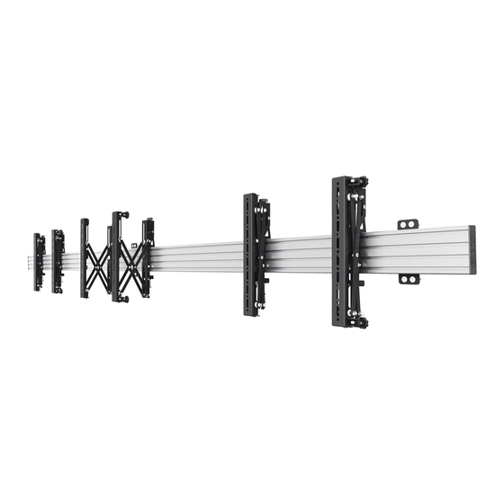
BT8331
UNIVERSAL POP-OUT MENU BOARD
MOUNTING SYSTEM
INSTALLATION GUIDE & PARTS LIST
This Pack Contains 1 Wall Mounting Kit
PLEASE KEEP THIS FOR FUTURE REFERENCE
Configurations may differ from the ones
shown in this installation manual
Installation Safety Notes.....................................................................................................................2
Parts List.............................................................................................................................................4
Installation Instructions........................................................................................................................6
Product Dimensions..........................................................................................................................18
B-Tech Contact Details.....................................................................................................................20
INSTALLATION TOOLS REQUIRED
Crosshead
screwdriver
CONTENTS
Drill
Drill bit
B-TECH AV MOUNTS
www.btechavmounts.com
FEATURES
• Universal multi-screen wall mount suitable for
all screens
• Max weight per screen: 50kg (110lbs)
• Suitable for landscape or portrait mounting
• Features pop-in, pop-out function to allow access
to the rear of screens for servicing and
maintenance and to aid installation
• Depth to wall: 104mm (+/-10mm micro-adjustment)
• Tool-less micro-adjustments for seamless
display alignment
• Safety screws help prevent unauthorised
removal of screens
• All mounting hardware included
50kg
PER SCREEN
Pencil
Level
TM
Stud finder
(optional)
Advertisement

Subscribe to Our Youtube Channel
Related Manuals for B-Tech SYSTEM X BT8331


Summary of Contents for B-Tech SYSTEM X BT8331
- Page 1 Configurations may differ from the ones 50kg shown in this installation manual PER SCREEN CONTENTS Installation Safety Notes........................2 Parts List.............................4 Installation Instructions........................6 Product Dimensions..........................18 B-Tech Contact Details........................20 INSTALLATION TOOLS REQUIRED Stud finder Crosshead Drill Drill bit Pencil Level (optional) screwdriver B-TECH AV MOUNTS www.btechavmounts.com...
- Page 2 Please check carefully to make sure there are no missing or defective parts - defective parts must never be used. B-Tech International Limited, its distributors and dealers are not liable or responsible for damage or injury caused by improper installation, improper use or failure to observe these safety instructions. In such cases, all guarantees will expire.
- Page 4 BT8331 PARTS LIST OPTIONAL OPTIONAL MOUNTING RAIL INTERFACE ADAPTOR ARMS EXTENSION KIT BT7564 BT7565 BT7566 BT8390-EXT...
- Page 5 RAIL FIXING KIT WALL PLATE M8 SLIDING NUT M8 x 12mm CSK SCREW 5AF HEX KEY MOUNTING RAIL EXTENSION KIT (OPTIONAL) SCREEN FIXING KIT SCREEN INTERFACE KIT LEFT INTERFACE ARM RIGHT INTERFACE ARM ADJUSTABLE BRACE M5 x 6mm SCREW M6 x 35mm SCREW 3AF HEX KEY 4AF HEX KEY 5AF HEX KEY...
- Page 6 EXTENDING THE MOUNTING RAIL To extend the length of the Menu Board, use the BT8390-EXT to combine mounting rails Optional: Combining Mounting Rails using the BT8390-EXT i. On one side of the mounting rail (part 5) insert 4 x joining bars (part 7) half-way into each slot.
- Page 7 INSTALLATION INSTRUCTIONS Attach Wall Plate to Rail i. For each wall plate (part 1) used, insert 4 x M8 sliding nuts (part 2) into the mounting rail (part 5). Two in the top slot / two in the bottom slot.
- Page 8 ii. Attach the wall plate (part 1) to the mounting rail (part 5) by fastening Cont... M8 x 12mm screws (part 3) into the inserted M8 sliding nuts (part 2). Required quantity of Rail Fixing Brackets 2pcs for 0 - 2000mm 3pcs for 2100mm - 3500mm 4pcs for 3600mm - 6000mm 5pcs for 6100mm - 8000mm...
- Page 9 Fix Mounting Rail to the Wall i. Fix the mounting rail (part 5) to the wall using the wall fixings (parts A1 & A2). ii. Once mounted, attach end caps (part 6) to mounting rail (part 5).
- Page 10 Attach Interface Arms to Screen Fix the interface arms (parts 9 & 10) to the back of the screens using the screen fixing kit (parts A-J). Ensure the arms are positioned the correct way round and the same holes are used on both arms. SCREEN SCREEN RECESS...
- Page 11 Connect Interface Arms with the Adjustable Brace Note: Adjustable brace (part 11) is only suitable for horizontal VESA fixings from 400 - 600mm. i. Extend the adjustable brace (part 11) and fix at desired length by tightening the 2 screws. The 3 notches show the position for interface fixings at 400mm, 500mm and 600mm.
- Page 12 Mount Screen onto Rail Hook interface arms (part 9 & 10) into the top of the mounting rail (part 5). SCREEN SCREEN WALL WALL Align First Screen i. Lateral Adjustment Slide arms along the mounting rail (part 5) to laterally adjust screen to desired position. SCREEN...
- Page 13 ii. Height Adjustment (+/-20mm) Ensure the screen is level and parallel to floor using the height adjustment hand wheels on the interface arms. LEVEL SCREEN FLOOR HEIGHT ADJUSTMENT HAND WHEEL Compatible with a 6mm hex key (not supplied) Height adjustment guides to help with accurate screen alignment Do not adjust height...
- Page 14 iii. Depth Adjustment (+/-10mm) Ensure the screen corners are equidistant from the wall using the depth adjustment hand wheels on the interface arms. WALL SCREEN Depth adjustment guides to help with accurate screen alignment Do not adjust height past the min and max guide lines DEPTH ADJUSTMENT HAND WHEELS Compatible with a 6mm hex key (not supplied)
- Page 15 Add Remaining Screens to the Menu Board Hook on remaining screens. Use adjustments to ensure screens are aligned. During installation, pop screens out for easy access to adjustment hand wheels (see Step 6). Use Height Adjustment to align bottom/top of screens WALL SCREENS Use Depth Adjustment...
- Page 16 Servicing Screens Note: Ensure pop-out function is not disabled (see Step 10). Push centrally at the left and right of the screen to pop-out the mount. The screen will rest in the 'open' position for servicing. SCREENS Push Push WARNING Be careful not to damage screen when pushing.
- Page 17 Disabling Pop-Out Function (optional) To prevent interface arms from popping out, fully insert and tighten the M6 x 35mm screws ( part 13) at the padlock* symbol at the bottom of the interface arms (parts 9 & 10). Unlocked Position Locked Position part 13 fully inserted Do not fully insert part 13 when interface arms are popped out.
- Page 18 Pop-Out VESA 400mm Interface Arms with Micro-Adjustment FRONT VIEW SIDE VIEW - OPEN 18.8mm 100.7mm 237.2mm (Tolerance 1mm) 110.9mm 68.7mm (Closed depth) +/-10mm Depth Adjustment THESE DIMENSIONS ARE INTENDED AS A GUIDE ONLY AND B-TECH ACCEPTS NO LIABILITY FOR THE ACCURACY OF THE INFORMATION...
- Page 19 BT8390-050...
- Page 20 B-Tech AV Mounts is a division of B-Tech International Design & Manufacturing Ltd. B-Tech, Better By Design & System X are registered trademarks of B-Tech International Design & Manufacturing Ltd. All other brands and product names are trademarks of their respective owners.
Need help?
Do you have a question about the SYSTEM X BT8331 and is the answer not in the manual?
Questions and answers