Advertisement
Quick Links
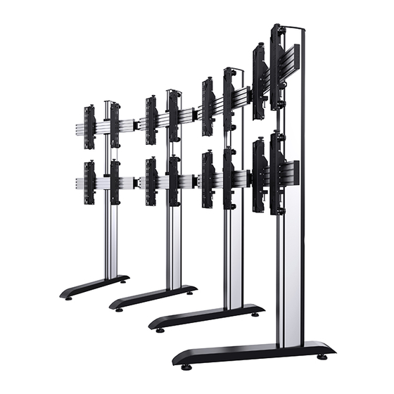
BT8373
UNIVERSAL CURVED VIDEOWALL STAND
INSTALLATION GUIDE & PARTS LIST
This Pack Contains 1 Stand
PLEASE KEEP THIS FOR FUTURE REFERENCE
Installation Safety Notes.....................................................................................................................2
Parts List.............................................................................................................................................4
Optional Accessories..........................................................................................................................6
Installation Instructions........................................................................................................................7
B-Tech Contact Details.....................................................................................................................24
INSTALLATION TOOLS REQUIRED
Crosshead
screwdriver
FEATURES
• Universal design suitable for all videowall screens
• Suitable for videowall screens from 39" - 70"
• Max weight per screen: 50kg (110lbs)
• Designed for screens with VESA
mounting patterns
• Tool-less micro-adjustments for seamless
• Easy to use angle adjustment with a range up to +/-45
• Universal screen position spacer to speed up the
• Includes adjustable levelling feet
• Integrated cable management
• Safety screws help prevent unauthorised removal
• All mounting hardware included
CONTENTS
10mm Spanner
B-TECH AV MOUNTS
www.btechavmounts.com
screen alignment
installation process
of screens
70"
177cm
Level
& non-VESA
®
50kg
Per Screen
Knife
TM
Advertisement

Related Manuals for B-Tech System X BT8373


Summary of Contents for B-Tech System X BT8373
- Page 1 • Safety screws help prevent unauthorised removal of screens • All mounting hardware included 70" 50kg 177cm Per Screen CONTENTS Installation Safety Notes........................2 Parts List.............................4 Optional Accessories..........................6 Installation Instructions........................7 B-Tech Contact Details........................24 INSTALLATION TOOLS REQUIRED Crosshead 10mm Spanner screwdriver Level Knife B-TECH AV MOUNTS www.btechavmounts.com...
- Page 4 BT8373 Due to the multiple installations available each option below PARTS LIST is dependent on the stand ordered. PLEASE KEEP THIS FOR FUTURE REFERENCE BASE BT8380-BASE ITEM PART NAME PER PACK BASE SUPPORT STEM M8 x 90mm SCREW M8 WASHER LEVELLING FOOT 6AF HEX KEY 24mm SPANNER...
- Page 5 ANGLE ADJUSTMENT CONNECTOR BT8390-AAC ITEM PART NAME PER PACK ANGLE CONNECTOR M8 x 16mm SCREW M8 WASHER M8 x 12mm SCREW M8 SLIDING NUT 5AF HEX KEY SPACER BT8390-SP PART NAME ITEM PER PACK SPACER INTERFACE KIT Screen Interface Arms BT8390-VESA400MAP BT8390-VESA400MAF PART NAME...
- Page 6 OPTIONAL ACCESSORIES Cable Management Clip BT8390-CMC Mount a B-Tech shelf to item B1 using items B6 & B5. Attach the BT8390-CMC cable management clips directly to item D1 to orgainse screen cables for a Use a BT8390-SA shelf adaptor to mount shelves neat and tidy installation.
- Page 7 OPTIONAL: EXTENDING THE COLUMNS i. Insert items B7 halfway into the non-threaded end of item B1. The two joining bars with grub screws go in the front of the column and the 2 joining bars with hex bolts go in the back. IMPORTANT: Joining bars should be inserted into the non-threaded end of the 180cm column.
- Page 8 INSTALLATION INSTRUCTIONS Attach Joining Plate to Column i. Connect together four item C3 with item C2 onto each item C1 using item C4. ii. Lay items B1 on the floor and slide two item C1 onto each item B1. IMPORTANT: Make sure the end with M8 threads are at the bottom of the columns.
- Page 9 iii. Use item F1 to set the distance between items C1 on item B1 according to the screen size. Once set, tighten item C3 with item C4. ADJUSTMENT KNOB Leave at least a 5mm gap at top of column for item B4...
- Page 10 Insert Sliding Nuts into Mounting Rails Lay items D1 on the floor. For each attachment of item C1, insert 4 x item C2 into item D1. Two in the bottom slot, two in the second from top slot. To attach item E1 to item D1, insert 4 x item E5 into the end of the rail. Two in each centre slot. Angle Adjustment Connector Column / Joining Plate Assembly...
- Page 11 Connect Rails Together using the Angle Adjustment i. Assemble items E2 and E3 to item E1. Do not fully tighten the screws and washers. ii. With the rails flat on the floor, fix item E1 to 2 x item D1 using items E3, E4 and E5. Make sure all rails are fixed using the same positions on item E1*.
- Page 12 Attach Columns to Rails On the floor, lay item B1 onto item D1. Attach item C1 to item D1 by fastening item C3 into the inserted items C2. To ensure straight assembly of item B1 make sure the distance of items C1 to the end of item D1 are set the same on each rail.
- Page 13 Assemble Bases to Columns Attach item A1 to item B1 using items A2, A3 & A4. Once bases are fixed to columns, return stand to upright position. THREADED NOTE: If necessary use item A7 to adjust item A5.
- Page 14 Fix Angle Set the angle required on item E1 and fully tighten all screws with item E6.
- Page 15 Attach Interface Arms to Screen (BT8390-VESA400MAF Arms) Attach items G1 & G2 to the back of the screens using items A-F. SCREEN FIXING KIT SCREEN Use spacers for screens with recessed fixings SCREEN Using Interface Adaptor Arms SCREEN FIXING KIT SCREEN NOTE: Portrait mounting shown.
- Page 16 Hook Screen onto the Stand Hook the first screen centrally onto the bottom rail and align screen with the horizontal centre of the trolley / stand...
- Page 17 Attaching Pop-Out Interface Arms to Screens (BT8390-VESA400MAP Arms) Attach items G1 & G2 to the back of the screens using items A-F. SCREEN SCREEN RECESS Use spacers (parts G, H & I) for screens with recessed fixings. ii. Connect interface arms with the adjustable brace Extend item G3 and fix at desired length by tightening the 2 screws.
- Page 18 iii. Fix item G3 to items G1 & G2 for easy lateral adjustment of screen. Hook Screen onto the Stand Hook the first screen centrally onto the bottom rail.
- Page 19 Mount and Align Screens i. Laterally adjust the screen to the desired position, ensure the screen is level and parallel to the floor using the micro-adjustment knobs on the interface arms - See Step 10. Lateral Adjustment X axis ii. Hook on the remaining flat screens. After mounting each screen use the micro-adjustment knobs on the items G1 &...
- Page 20 Align Screens using Micro-Adjustment i. Align the flat screen to the floor using the height adjustment knobs. ii. Use the depth adjustment knobs to ensure flat screen is perpendicular with the floor to ensure that each corner of the screen is aligned evenly. Micro-adjust top row first and work down row by row.
- Page 21 Secure Screens Once screens are aligned, tighten the safety screws on the bottom items G1 & G2 SAFETY SCREW Servicing Screens (Pop-Out Arms only) Parts G1 & G2 Push centrally at the left and right of the screen popped-out to pop-out the mount. The screen will rest in the Push 'open' position for servicing.
- Page 22 Add End Caps & Cable Management Covers Once all the screens and power cables are connected and if possible routed down the backs of item B1, partially clip on items B3, this allows easy removal if more cables need adding. Once satisfied all cables are fitted, clip items B3 on fully.
- Page 23 (Tolerance 1mm) +/-10mm Depth Adjustment 30mm 20mm 40.1mm BT8390-VESA400MAP 18.8mm 237.2mm (Tolerance 1mm) 100.7mm 68.7mm (Closed depth) 110.9mm +/-10mm Depth Adjustment THESE DIMENSIONS ARE INTENDED AS A GUIDE ONLY AND B-TECH ACCEPTS NO LIABILITY FOR THE ACCURACY OF THE INFORMATION...
- Page 24 B-Tech AV Mounts is a division of B-Tech International Design & Manufacturing Ltd. B-Tech, Better By Design & System X are registered trademarks of B-Tech International Design & Manufacturing Ltd. All other brands and product names are trademarks of their respective owners.
Need help?
Do you have a question about the System X BT8373 and is the answer not in the manual?
Questions and answers