Advertisement
Quick Links
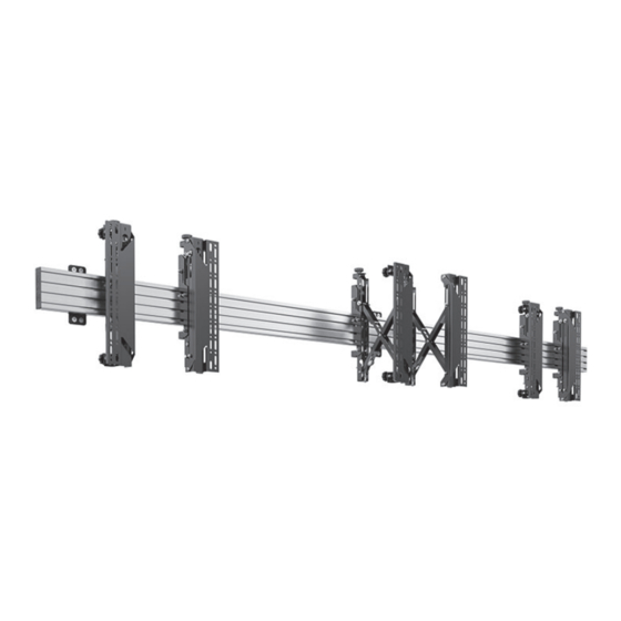
BT8341
UNIVERSAL POP-OUT
VIDEOWALL MOUNTING SYSTEM
INSTALLATION GUIDE
SPECIFICATIONS
• Recommended screen size: 39"- 70"
• Max weight per screen: 50kg (110lbs)
• Features pop-in, pop-out function to allow access to the rear of
screens for servicing and maintenance and to aid installation
• Tool-less micro-adjustments for seamless display alignment
• Suitable for landscape or portrait mounting
• Sections can be joined together to increase video wall width
• Safety screws help prevent unauthorised removal of screens
• All mounting hardware included
Please refer to page 4 for VESA® xings
Note: This assembly manual covers di erent installations. Some
parts or procedures shown may not be required for installation.
www.btechavmounts.com
TM
Advertisement

Related Manuals for B-Tech System X BT8341


Summary of Contents for B-Tech System X BT8341
- Page 1 BT8341 UNIVERSAL POP-OUT VIDEOWALL MOUNTING SYSTEM INSTALLATION GUIDE SPECIFICATIONS • Recommended screen size: 39”- 70" • Max weight per screen: 50kg (110lbs) • Features pop-in, pop-out function to allow access to the rear of screens for servicing and maintenance and to aid installation •...
- Page 2 It is recommended that periodic inspections of the product and its xing points are made as frequently as possible (no more than 6 months apart) to ensure that safety is maintained. B-Tech AV Mounts recommends that a suitably quali ed person is used for the removal of this product.
- Page 4 BT8341 PARTS LIST RAIL MOUNTING BRACKET PLEASE KEEP THIS FOR FUTURE REFERENCE BT8390-WFK1 Due to the multiple installations available the quantity for each option below is dependent on the mount ordered. MOUNTING RAIL BT8390-070 BT8390-050 BT8390-150 Length: 70cm Length: 50cm Length: 150cm BT8390-175 BT8390-200...
- Page 5 ITEM PART NAME PER PACK RAIL MOUNTING BRACKET WALL FIXING PLATE ST8 x 45mm CSK WOOD SCREW No.10 WALL PLUG M8 SLIDING NUT M8 x 12mm CSK SCREW 5AF HEX KEY MOUNTING RAIL MOUNTING RAIL END CAP RAIL EXTENSION KIT (OPTIONAL) JOINING BAR M6 x 8mm GRUB SCREW 3AF HEX KEY...
- Page 6 TYPICAL INSTALLATION 2 x 2 Videowall installation with VESA 400 Micro-Adjustment Pop-Out Arms ASSEMBLED SIDE VIEW CLOSED OPEN BT8390-VESA400MAP BT8390-WFK1 Centre of BT8390 Rail BT8390 Rail Distance from wall 105.4mm (Tolerance 1mm) 273.9mm (Tolerance 1mm) +/-10mm Depth Adjustment +/-10mm Depth Adjustment...
- Page 7 OPTIONAL EXTENDING THE mounting rail COMBINING MOUNTING RAILS i. On one side of item 7, insert 4x item 9 half-way into each channel. ii On the back side of item 7, insert 1x item 9 in the second channel and 1 x item 9 in the third channel - See Fig. 1 iii.
- Page 8 INSTALLATION INSTRUCTIONS ASSEMBLE WALL PLATES TO MOUNTING RAIL i. For each item 1 used insert 2x item 4 into item 7. 1 in the top channel and 1 in the bottom channel.
- Page 9 ii. Attach item 1 to item 7 by fastening item 5 into item 4. Required quantity of Wall Plates (item 1) 2pcs for up to 2000mm (0 - 79") 3pcs for 2100mm - 3500mm (80" - 139") 4pcs for 3600mm - 6000mm (140" - 239") 5pcs for 6100mm - 8000mm (240"...
- Page 10 INSTALLING THE MOUNT i. Determine the centre of the rst screen at the bottom left. Mark the centre, for the centre of the rail. WALL ii. Mark and drill two xing holes for each item 1 assembled. Insert item 3 and the top item 2. Do not fully tighten - Allow a gap (approx.10mm).
- Page 11 ATTACH INTERFACE ARMS TO SCREEN Fix items 12 & 13 to the rear of the screen using items A-J. Note: Ensure the arms are facing the correct way round and the same holes are used on both arms. SCREEN RECESS SCREEN Use spacers (items H, I &...
- Page 12 CONNECT INTERFACE ARMS WITH THE ADJUSTABLE BRACE Note: Adjustable brace (item 14) is only suitable for horizontal VESA xings from 400 - 600mm. i. Extend item 14 and x at desired length by tightening the 2 screws. Note: The 3 notches show the position for interface xings at 400mm, 500mm and 600mm. For screens with interface holes 600mm apart, extend item 14 to the 600 settting.
- Page 13 HOOK SCREEN ONTO RAIL Hook the rst screen onto bottom rail. Y AXIS WALL KNOB Z AXIS KNOB WALL Z AXIS KNOB Note: Ensure safety screw is not engaged SCREEN ALIGNMENT i. Lateral Adjustment Position the 1st screen at the bottom left corner of the video wall. SCREEN Lateral Adjustment X Axis FLOOR...
- Page 14 ii. Height Adjustment (Y Axis +/-20mm) Ensure the screen is level and parallel to oor using the height adjustment hand wheels on the interface arms. LEVEL SCREEN FLOOR HEIGHT ADJUSTMENT HAND WHEEL (Y AXIS) Compatible with a 6mm hex key (not supplied) Height adjustment guides to help with accurate screen alignment...
- Page 15 iii. Depth Adjustment (Z Axis +/-10mm) Ensure the screen corners are equidistant from the wall using the depth adjustment hand wheels on the interface arms. Distance to wall WALL SCREEN Distance to wall Depth adjustment guides to help with accurate screen alignment Do not adjust height past the min and...
- Page 16 MOUNT REMAINING SCREENS ONTO RAILS Starting on the left side, hook the remaining screens onto the rails Note: Use a plumb to align the rst column of screens. After mounting each screen use the Y & Z micro-adjustment knobs on items 12 & 13 to level and align the screens.
- Page 17 Note: During installation, pop screens out for easy access to adjustment hand wheels - see Step 6. All screen fronts should be ush. WALL PLUMB SCREENS Pop-out screens for easy access to adjustment hand wheels SECURE INTERFACE ARMS TO MOUNTING RAILS Tighten the safety screws on items 12 &...
- Page 18 OPERATING & SERVICING SCREENS Note: Ensure pop-out function is not disabled - see Step 10. Push centrally at the left and right of the screen to pop-out the mount. After servicing, push screen back and click into original position. The screen will rest in the 'open' position for servicing. Screen in service position items 12 &...
- Page 19 SIDE VIEW 30mm INTERFACE ARMS 18.8mm 100.7mm 237.2mm (Tolerance 1mm) 110.9mm 68.7mm (Closed depth) +/-10mm Depth Adjustment THESE INSTRUCTIONS ARE INTENDED AS A GUIDE ONLY AND B-TECH ACCEPTS NO LIABILITY FOR THE ACCURACY OF THE INFORMATION CONTAINED IN THIS DOCUMENT.
- Page 20 ©2021 B-Tech International Design and Manufacturing Ltd. All rights reserved. B-Tech AV Mounts is a division of B-Tech International Design and Manufacturing Ltd. B-Tech AV Mounts and the B-Tech logo are registered trade marks. All other brands and product names are trademarks of their respective owners.
Need help?
Do you have a question about the System X BT8341 and is the answer not in the manual?
Questions and answers