Advertisement
Quick Links
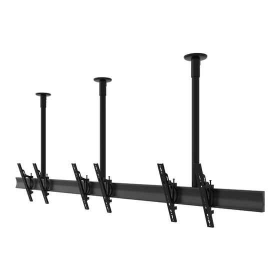
BT8332
UNIVERSAL CEILING MOUNTED
MENU BOARD MOUNTING SYSTEM
INSTALLATION GUIDE
SPECIFICATIONS
• Recommended screen size: 32"- 70"
• Max weight per screen: 50kg (110lbs)
• Suitable for landscape or portrait mounting
• Sections can be joined together to increase menu board width
• Safety screws help prevent unauthorised removal of screens
• All mounting hardware included
Note: This assembly manual covers di erent installations. Some
parts or procedures shown may not be required for installation.
Please refer to page 5
for VESA® xings
www.btechavmounts.com
TM
PER SCREEN
Advertisement

Related Manuals for B-Tech SYSTEM X BT8332


Summary of Contents for B-Tech SYSTEM X BT8332
- Page 1 BT8332 UNIVERSAL CEILING MOUNTED MENU BOARD MOUNTING SYSTEM INSTALLATION GUIDE SPECIFICATIONS • Recommended screen size: 32”- 70" • Max weight per screen: 50kg (110lbs) • Suitable for landscape or portrait mounting • Sections can be joined together to increase menu board width •...
- Page 2 It is recommended that periodic inspections of the product and its xing points are made as frequently as possible (no more than 6 months apart) to ensure that safety is maintained. B-Tech AV Mounts recommends that a suitably quali ed person is used for the removal of this product.
- Page 4 BT8332 PARTS LIST Due to the multiple installations available the quantity for each option below is dependent on the mount ordered. All these components can be moved or carried by manpower. Please be careful to avoid injury when PLEASE KEEP THIS FOR FUTURE REFERENCE handling these components before &...
- Page 5 OPTIONAL MOUNTING RAIL EXTENSION KIT BT8390-EXT PART NAME ITEM PER PACK JOINING BAR M6 x 8mm GRUB SCREW 3AF HEX KEY OPTIONAL BT7824 POLE EXTENSION KIT ITEM PART NAME PER PACK BT7823 EXTERNAL JOINER M8 GRUB SCREW ITEM PART NAME M8 x 60mm SCREW PER PACK M8 x 12mm SCREW...
-
Page 6: Typical Installation
TYPICAL INSTALLATION INSTALLATION TOOLS REQUIRED 2 x 1 Menu Board installation with VESA 400 Fixed Arms Crosshead Drill Pencil screwdriver Level (Optional) CABLE CABLE MANAGEMENT Route any screen cables through the CEILING bottom of the pole and out through CABLE the top of the mount or use the cable management hole on the back of item A1. - Page 7 OPTIONAL EXTENDING THE mounting rail COMBINING MOUNTING RAILS i. On one side of item E1, insert 4x item F1 half-way into each channel. ii On the back side of item E1, insert 1x item F1 in the second channel and 1 x item F1 in the third channel - See Fig. 1 iii.
- Page 8 OPTIONAL COMBINING THE EXTENSION POLES BT7823 INTERNAL POLE JOINER iii. Slide item B1 onto the bottom of item G1 and i. Insert item G1 into the bottom of item B1, lining align the bottom screw holes on item G1 up the top screw holes on item G1 with the holes with the holes on the pole.
-
Page 9: Installation Instructions
INSTALLATION INSTRUCTIONS CEILING PLATE FIXING DIMENSIONS FIX CEILING PLATE Fix item A1 to the ceiling using suitable xings (not supplied). 10.5mm CEILING Optional 120mm depending on the type of ceiling Note: Space item A1 the same distance apart as item C1 on item E1. ATTACH POLE TO CEILING PLATE ii. - Page 10 ASSEMBLE COLLARS ONTO RAILS Assembly using 2 single collars i. Attach item C1 onto item D1. Note: Ensure items C2 are positioned on the back of item C1. ii. Insert 2x item D2 into the top channel of item E1 and 2x item D2 in the bottom channel.
- Page 11 FIX RAIL ONTO POLE(S) i. Slide items C1 & E1 onto item B1, aligning the pole hole with the collar hole and fasten items C2. ii. Insert item C3 through item C1 & B1, securing the rail to the pole. POLE HOLE COLLAR HOLE...
- Page 12 ATTACH INTERFACE ARMS TO SCREEN Fix items H1 & H2 to the rear of the screen using items A-M. Note: Ensure the arms are A. FIXED ARMS facing the correct way round and the same holes are used on both arms. SCREEN FIXING KIT SCREEN...
- Page 13 C. MICRO-ADJUSTMENT ARMS Fix items H1 & H2 to the rear of the screen using items D-N. Note: Ensure the arms are facing the correct way SCREEN FIXING KIT round and the same holes are used on both arms. Note: Use spacers for screens with recessed xings SCREEN SCREEN OPTIONAL ADAPTOR ARMS...
- Page 14 HOOK SCREEN ONTO RAIL i. Hook the rst screen centrally onto item B1. ii. Using a level, align the screen to the oor using the Y axis adjustment knob on items H1 & H2* *Only available with Micro-adjustment arms - See page 15. iii.
- Page 15 Y AXIS SCREEN ALIGNMENT USING MICRO-ADJUSTMENT KNOB (Only available with BT8390-VESA400MAF) Z AXIS KNOB i. Use the Y & Z micro-adjustment knobs on items H1 & H2 to align screens. Z AXIS KNOB Use Lateral Adjustment Use Height Adjustment* Use Depth Adjustment* (X axis) to align sides of screens (Y axis knob) to align bottom/top of screens (Z axis knobs) to align front of screens...
- Page 16 BT8332 DIMENSIONS PLEASE KEEP THIS FOR FUTURE REFERENCE DEPTH OF INSTALL USING DEPTH OF INSTALL USING DEPTH OF INSTALL USING INTERFACE ARMS FIXED INTERFACE ARMS INTERFACE ARMS WITH TILT WITH MIRCO-ADJUSTMENT 157.5mm 40mm Ø50.8mm BT8390-VESA400MAF BT8390-VESA200T BT8390-VESA200F BT8390-VESA400T BT8390-VESA400F 75mm 57.8mm 47.8mm (Tolerance...
- Page 17 Fixed VESA 400mm Interface Arms VESA 400mm Interface Arms with Tilt 20° 45.2mm 75mm 15° 10° 28mm 40mm THESE INSTRUCTIONS ARE INTENDED AS A GUIDE ONLY AND B-TECH ACCEPTS NO LIABILITY FOR THE ACCURACY OF THE INFORMATION CONTAINED IN THIS DOCUMENT.
-
Page 18: Ceiling Mount
REAR VIEW 35.7mm POLE ASSEMBLY EXAMPLE BT7822 120mm TOP VIEW 157.5mm 45mm 4x 10.5mm BT7850-050 0.5M POLE 50.8mm THESE INSTRUCTIONS ARE INTENDED AS A GUIDE ONLY AND B-TECH ACCEPTS NO LIABILITY FOR THE ACCURACY OF THE INFORMATION CONTAINED IN THIS DOCUMENT. -
Page 19: Mounting Rails
500mm 705mm 505mm BT8390-150 1500mm 1505mm BT8390-175 1750mm 1755mm BT8390-200 2000mm 2005mm 30mm 30mm 8.2mm 30mm 30mm THESE INSTRUCTIONS ARE INTENDED AS A GUIDE ONLY AND B-TECH ACCEPTS NO LIABILITY FOR THE ACCURACY OF THE INFORMATION CONTAINED IN THIS DOCUMENT. - Page 20 ©2021 B-Tech International Design and Manufacturing Ltd. All rights reserved. B-Tech AV Mounts is a division of B-Tech International Design and Manufacturing Ltd. B-Tech AV Mounts and the B-Tech logo are registered trade marks. All other brands and product names are trademarks of their respective owners.
Need help?
Do you have a question about the SYSTEM X BT8332 and is the answer not in the manual?
Questions and answers